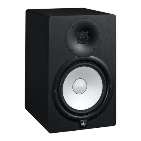
Yamaha STAGEPAS 150M Building instructions

SERVICE MANUAL
SPECIFICATIONS(総合仕様)..................................................................... 3
PANEL LAYOUT(パネルレイアウト)......................................................... 4
DIMENSIONS(寸法図).............................................................................. 4
CIRCUIT BOARD LAYOUT(ユニットレイアウト).................................... 5
DISASSEMBLY PROCEDURES(分解手順)............................................... 6
IC BLOCK DIAGRAM(ICブロック図)...................................................... 15
CIRCUIT BOARDS(シート基板図)........................................................... 16
INSPECTIONS(検査)............................................................................... 27
ADJUSTMENT OF AMPLIFIER(アンプユニットの調整)........................ 29
PARTS LIST
BLOCK & LEVEL DIAGRAM(ブロック&レベルダイアグラム)
CIRCUIT DIAGRAM(回路図)
■CONTENTS(目次)
PA 011900
20080527-65100
Copyright (c) Yamaha Corporation. All rights reserved. 08.05
HAMAMATSU, JAPAN
Mixer
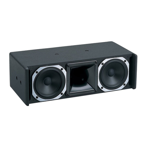
Speaker
w
w
w
.
x
i
a
o
y
u
1
6
3
.
c
o
m
Q
Q
3
7
6
3
1
5
1
5
0
9
9
2
8
9
4
2
9
8
T
E
L
1
3
9
4
2
2
9
6
5
1
3
9
9
2
8
9
4
2
9
8
0
5
1
5
1
3
6
7
3
Q
Q
TEL 13942296513 QQ 376315150 892498299
http://www.xiaoyu163.com
STAGEPAS 150M
2
■WARNING
Components having special characteristics are marked and must be replaced with parts having specification equal to those originally
installed.
印の部品は、安全を維持するために重要な部品です。交換する場合は、安全のために必ず指定の部品をご使用ください。
IMPORTANT NOTICE
This manual has been provided for the use of authorized Yamaha Retailers and their service personnel. It has been assumed that basic service
procedures inherent to the industry, and more specifically Yamaha Products, are already known and understood by the users, and have
therefore not been restated.
WARNING: Failure to follow appropriate service and safety procedures when servicing this product may result in personal injury, destruc-
tion of expensive components and failure of the product to perform as specified. For these reasons, we advise all Yamaha
product owners that all service required should be performed by an authorized Yamaha Retailer or the appointed service
representative.
IMPORTANT: This presentation or sale of this manual to any individual or firm does not constitute authorization, certification, recognition of
any applicable technical capabilities, or establish a principal-agent relationship of any form.
The data provided is believed to be accurate and applicable to the unit(s) indicated on the cover. The research engineering, and service
departments of Yamaha are continually striving to improve Yamaha products. Modifications are, therefore, inevitable and changes in specifica-
tion are subject to change without notice or obligation to retrofit. Should any discrepancy appear to exist, please contact the distributor’s Service
Division.
WARNING: Static discharges can destroy expensive components. Discharge any static electricity your body may have accumulated by
grounding yourself to the ground bus in the unit (heavy gauge black wires connect to this bus).
IMPORTANT: Turn the unit OFF during disassembly and parts replacement. Recheck all work before you apply power to the unit.
IMPORTANT NOTICE FOR THE UNITED KINGDOM
Connecting the Plug and Cord
WARNING: THIS APPARATUS MUST BE EARTHED
IMPORTANT. The wires in this mains lead are coloured in accordance with the following code:
GREEN-AND-YELLOW: EARTH
BLUE: NEUTRAL
BROWN: LIVE
As the colours of the wires in the mains lead of this apparatus may not correspond with the coloured markings identifying the terminals in your
plug, proceed as follows:
The wire which is coloured GREEN and YELLOW must be connected to the terminal in the plug which is marked by the letter E or by the safety
earth symbol or colored GREEN or colored GREEN and YELLOW.
The wire which is coloured BLUE must be connected to the terminal which is marked with the letter N or coloured BLACK.
The wire which is coloured BROWN must be connected to the terminal which is marked with the letter L or coloured RED.
WARNING: This product contains chemicals known to the State of California to cause cancer, or birth defects or other reproductive harm.
DO NOT PLACE SOLDER, ELECTRICAL/ELECTRONIC OR PLASTIC COMPONENTS IN YOUR MOUTH FOR ANY REASON WHAT SO
EVER!
Avoid prolonged, unprotected contact between solder and your skin! When soldering, do not inhale solder fumes or expose eyes to solder/flux
vapor!
If you come in contact with solder or components located inside the enclosure of this product, wash your hands before handling food.
w
w
w
.
x
i
a
o
y
u
1
6
3
.
c
o
m
Q
Q
3
7
6
3
1
5
1
5
0
9
9
2
8
9
4
2
9
8
T
E
L
1
3
9
4
2
2
9
6
5
1
3
9
9
2
8
9
4
2
9
8
0
5
1
5
1
3
6
7
3
Q
Q
TEL 13942296513 QQ 376315150 892498299
http://www.xiaoyu163.com
STAGEPAS 150M
3
■SPECIFICATIONS ■ 総合仕様
●General Specifications
Maximum Output Power
150 W (±10 %)/4 Ω@ 10 % THD at 1 kHz (SPEAKER)
≥100 W/4 Ω@ 1 % THD at 1 kHz (SPEAKER)
Maximum Output Level
112 dB (1 m)
Frequency Response (Nomimal output level @ 1 kHz)
-3 dB, 0 dB, +1 dB @ 20 Hz–20 kHz
(MUSIC/SPEECH=MUSIC) (ST SUB OUT)
-3 dB, 0 dB, +1 dB @ 80 Hz–20 kHz
(MUSIC/SPEECH=SPEECH) (ST LINK OUT)
-3 dB, 0 dB, +1 dB @ 20 Hz–20 kHz, 1 W Output
(MUSIC/SPEECH=MUSIC, without Speaker EQ)
(SPEAKER)
Total Harmonic Distortion
≤0.5 % @ 20 Hz, 1 kHz, 20 kHz +14 dBu GAIN=nominal
(ST SUB OUT, ST LINK OUT)
Hum & Noise
(Equivalent Input Noise, Rs=150 Ω, MIC/LINE=MIC)
≤-112 dBu (CH1/2)
≤-65 dBu Residual output noise (SPEAKER)
Crosstalk (1 kHz)
≤-70 dB between input channels
Power Consumption
20 W
Weight
9.6 kg (Speaker + Powered Mixer)
Stereo Input Channel Equalization
±15 dB
HIGH : 10 kHz shelving
LOW : 100 Hz shelving
●Speaker (300S)
Enclosure
2 way bass-reflex type, Polypropylene, Black
Crossover Frequency
4.0 kHz (LF: 12 dB/oct, HF: 12 dB/oct)
Frequency Range
55 Hz–20 kHz (-10 dB)
Speaker Unit
LF : 8" (20 cm) Cone
HF : 1" (2.54 cm) Compression Driver
●一般仕様
最大出力
150W(±10%)/4Ω@10%THDat1kHz(SPEAKER)
≧100W/4Ω@1%THDat1kHz(SPEAKER)
最大出力音圧レベル
112dB(軸上1m)
周波数特性(ノミナル出力レベル@1kHz)
-3dB、0dB、+1dB@20Hz〜20kHz
(MUSIC/SPEECH=MUSIC)(STSUBOUT)
-3dB、0dB、+1dB@80Hz〜20kHz
(MUSIC/SPEECH=SPEECH)(STLINKOUT)
-3dB、0dB、+1dB@20Hz〜20kHz、1W出力
(MUSIC/SPEECH=MUSIC、スピーカーEQを除く)
(SPEAKER)
全高調波歪率
≦0.5%@20Hz、1kHz、20kHz+14dBuGAIN=すべてノ
ミナル(STSUBOUT、STLINKOUT)
ハム&ノイズ
(入力換算ノイズ、Rs=150Ω、MIC/LINEスイッチ=MIC)
≦-112dBu(CH1/2)
≦-65dBu残留ノイズ(SPEAKER)
クロストーク(1kHz)
≦-70dB入出力間
消費電力
20W
質量
9.6kg(スピーカー+ミキサー)
入力チャンネルイコライザー特性
最大可変幅(±15dB)
HIGH:10kHzシェルビングタイプ
LOW :100Hzシェルビングタイプ
●スピーカー(300S)
エンクロージャー
2-wayバスレフ型、ポリプロピレン、黒
クロスオーバー周波数
4.0kHz(LF:12dB/oct、HF:12dB/oct)
再生周波数帯域
55Hz〜20kHz(-10dB)
スピーカーユニット
LF :8"(20cm)コーン
HF:1"(2.54cm)コンプレッションドライバー
w
w
w
.
x
i
a
o
y
u
1
6
3
.
c
o
m
Q
Q
3
7
6
3
1
5
1
5
0
9
9
2
8
9
4
2
9
8
T
E
L
1
3
9
4
2
2
9
6
5
1
3
9
9
2
8
9
4
2
9
8
0
5
1
5
1
3
6
7
3
Q
Q
TEL 13942296513 QQ 376315150 892498299
http://www.xiaoyu163.com
STAGEPAS 150M
4
275
Speaker
(スピーカー部)
137
120
2-M8x25
Mixer
(ミキサー部)
160
96.3
255
455.5
5.5 450
5
290
285
AC IN jack
POWER switch
SPEAKER jack (for included speaker 300S only)
ST LINK OUT R jack
PHONES jack
ST SUB OUT L (MONO) / R jacks
ST SUB OUT control
PHONES control
Channel input jacks (CH 1, 2)
Stereo channel input jacks (CH 3/4, 5/6, 7/8)
MIC/LINE switch
Equalizer
REVERB switch
REVERB control
CLICK switch (for headphones/speaker)
LEVEL control
MASTER LEVEL Control
CLICK switch (for headphones)
SPEECH/MUSIC switch
LEVEL meter
POWER indicator
1
2
3
4
5
6
7
8
9
0
A
B
C
D
E
F
G
H
I
J
K
1
2
3
4
5
6
7
8
9
0
A
B
C
D
E
F
G
H
I
J
K
ACIN端子
POWERスイッチ
SPEAKER端子(付属のスピーカー(300S)専用)
STLINKOUTR端子
PHONES端子
STSUBOUTL(MONO)/R端子
STSUBOUTコントロール
PHONESコントロール
チャンネル入力端子(CH1、2)
ステレオチャンネル入力端子(CH3/4、5/6、7/8)
MIC/LINEスイッチ
EQ(イコライザー)
REVERBスイッチ
REVERBコントロール
CLICKスイッチ(ヘッドフォン/スピーカー用)
LEVELコントロール
MASTERLEVELコントロール
CLICKスイッチ(ヘッドフォン用)
SPEECH/MUSICスイッチ
LEVELメーター
POWERインジケーター
■PANEL LAYOUT(パネルレイアウト)
6
BA E
G
I
C
F
1 2 KJ8 7 D
H
3
4
5
9
0
■DIMENSIONS(寸法図)
Unit: mm
単位:mm
w
w
w
.
x
i
a
o
y
u
1
6
3
.
c
o
m
Q
Q
3
7
6
3
1
5
1
5
0
9
9
2
8
9
4
2
9
8
T
E
L
1
3
9
4
2
2
9
6
5
1
3
9
9
2
8
9
4
2
9
8
0
5
1
5
1
3
6
7
3
Q
Q
TEL 13942296513 QQ 376315150 892498299
http://www.xiaoyu163.com

STAGEPAS 150M
5
■CIRCUIT BOARD LAYOUT(ユニットレイアウト)
CONTROL
CONTROL
INPUT
POWER
Speaker HF <Tweeter>
(スピーカHF<ツィーター>)
Front view Right side view
NETWORK NETWORK REVERB
POWER
Speaker LF <Woofer>
(スピーカLF<ウーファー>)AMPAMP
REVERB
Rear view
SP OUT
SP BOX IN
w
w
w
.
x
i
a
o
y
u
1
6
3
.
c
o
m
Q
Q
3
7
6
3
1
5
1
5
0
9
9
2
8
9
4
2
9
8
T
E
L
1
3
9
4
2
2
9
6
5
1
3
9
9
2
8
9
4
2
9
8
0
5
1
5
1
3
6
7
3
Q
Q
TEL 13942296513 QQ 376315150 892498299
http://www.xiaoyu163.com

STAGEPAS 150M
6
[80B]
[80B] [80B]
[80B]
Rear cabinet unit
(リアキャビネット部)
Front grille assembly
(フロントグリルAss'y)
[80A]
[100]
[80A]
[120]
[120]
[100]
[80A]
[120]
[100]
[80A]
[120]
[100]
[80A]
Speaker LF (Woofer)
(スピーカLF(ウーファー))
Front cabinet unit
(フロントキャビネット部)
1. Front Grille Assembly
(Time required: About 1 minute)
1-1 Remove the four (4) screws marked [120]. The front
grille assembly can then be removed. (Fig. 1)
2. Speaker LF (Woofer)
(Time required: About 2 minutes)
2-1 Remove the front grille assembly. (See procedure 1)
2-2 Remove the four (4) screws marked [100]. The
speaker LF (woofer) can then be removed. (Fig. 1)
2-3 Remove the wire LF (red/black) attached to the speaker
LF (woofer). (Photo. 1)
3. Front Cabinet Unit, Rear Cabinet Unit
(Time required: About 3 minutes)
3-1 Remove the front grille assembly. (See procedure 1)
3-2 Remove the five (5) screws marked [80A] and four (4)
screws marked [80B]. The front cabinet unit and rear
cabinet un t can then be separated. (Fig. 1, 2)
3-3 Remove the wire LF (red/black) attached to the speaker
LF (woofer). (Photo. 1)
3-4 Remove the wire HF (yellow/blue) attached to the
speaker HF (tweeter). (Photo. 2)
* Take care not to open the front cabinet unit and
rear cabinet unit too wide or the speaker LF
(woofer) terminal and speaker HF (tweeter) ter-
minal may be damaged.
<Front view>
Fig. 1(図 1)
<Rear view>
1. フロントグリルAssy(所要時間:約1分)
1-1 [120]のネジ4本を外して、フロントグリルAssyを外し
ます。(図1)
2. スピーカLF(ウーファー)(所要時間:約2分)
2-1 フロントグリルAssyを外します。(1項参照)
2-2 [100]のネジ4本を外して、スピーカLF(ウーファー)を
外します。(図1)
2-3 スピーカLF(ウーファー)に取り付けられている束線LF
(赤/黒)を外します。(写真1)
3. フロントキャビネット部、リアキャビネット部
(所要時間:約3分)
3-1 フロントグリルAssyを外します。(1項参照)
3-2 [80A]のネジ5本と[80B]のネジ4本を外して、フロント
キャビネット部、リアキャビネット部を別けます。(図
1、2)
3-3 スピーカLF(ウーファー)に取り付けられている束線LF
(赤/黒)を外します。(写真1)
3-4 スピーカHF(ツィーター)に取り付けられている束線
HF(黄/青)を外します。(写真2)
※ フロントキャビネット部とリアキャビネット部を開
きすぎて、スピーカLF(ウーファー)端子、スピー
カHF(ツィーター)端子を傷めないように注意して
ください。
■DISASSEMBLY PROCEDURES(分解手順)
Fig. 2(図 2)
[80A]: BINDHEADTAPPINGSCREW-A5.0x35NI-BL(AAX61640)
A タイト+ BIND
[100]: BINDHEADTAPPINGSCREW-B4.0x18NI-BL(AAX61660)
B タイト+ BIND
[120]: BINDHEADTAPPINGSCREW-B4.0x10NI-BL(AAX61680)
B タイト+ BIND
[80B]: BINDHEADTAPPINGSCREW-A5.0x35NI-BL(AAX61640)
A タイト+ BIND
w
w
w
.
x
i
a
o
y
u
1
6
3
.
c
o
m
Q
Q
3
7
6
3
1
5
1
5
0
9
9
2
8
9
4
2
9
8
T
E
L
1
3
9
4
2
2
9
6
5
1
3
9
9
2
8
9
4
2
9
8
0
5
1
5
1
3
6
7
3
Q
Q
TEL 13942296513 QQ 376315150 892498299
http://www.xiaoyu163.com
STAGEPAS 150M
7
[13] x 4
Network assembly
(ネットワークAss'y)
Network holder C
(ネットワーク固定金具C)
Network holder D
(ネットワーク固定金具D)
Rear cabinet unit
(リアキャビネット部)
NETWORK
[N40] x 4
Wire LF (Red)
(束線LF(赤))
Speaker LF (Woofer)
(スピーカLF(ウーファー))
Wire LF (Black)
(束線LF(黒))
Wire HF (Blue)
(束線HF(青))
Wire HF (Yellow)
(束線HF(黄))
Speaker HF (Tweeter)
(スピーカHF(ツィーター))
Photo 2(写真 2)Photo 1(写真 1)
4. Speaker HF (Tweeter)
(Time required: About 4 minutes)
4-1 Remove the front grille assembly. (See procedure 1)
4-2 Separate the front cabinet unit and rear cabinet unit.
(See procedure 3)
4-3 Remove the two (2) screws marked [70]. The speaker
HF (tweeter) can then be removed from the front cabi-
net unit. (Fig. 3)
5. Network Assembly, NETWORK Circuit Board
(Time required: About 7 minutes)
5-1 Remove the front grille assembly. (See procedure 1)
5-2 Separate the front cabinet unit and rear cabinet unit.
(See procedure 3)
5-3 Remove the four (4) screws marked [13]. The network
assembly can then be removed from the rear cabinet
unit. (Fig. 4)
5-4 Remove the four (4) screws marked [N40]. The NET-
WORK circuit board and the network holders C and D
can then be separated. (Fig. 4)
Fig. 3(図3)
Fig. 4(図 4)
4. スピーカHF(ツィーター)(所要時間:約4分)
4-1 フロントグリルAssyを外します。(1項参照)
4-2 フロントキャビネット部、リアキャビネット部を別け
ます。(3項参照)
4-3 [70]のネジ2本を外して、フロントキャビネット部から
スピーカHF(ツィーター)を外します。(図3)
5. ネットワークAssy、NETWORKシート
(所要時間:約7分)
5-1 フロントグリルAssyを外します。(1項参照)
5-2 フロントキャビネット部、リアキャビネット部を別け
ます。(3項参照)
5-3 [13]のネジ4本を外して、リアキャビネット部からネッ
トワークAssyを外します。(図4)
5-4 [N40]のネジ4本を外して、NETWORKシートとネット
ワーク固定金具C、Dを別けます。(図4)
[70]
Front cabinet unit
(フロントキャビネット部)
Speaker HF (Tweeter)
(スピーカHF(ツィーター))
[70]: BINDHEADTAPPINGSCREW-B4.0x20NI-BL(AAX61630)
B タイト+ BIND
[13]: BINDHEADTAPPINGSCREW-B3.0x10NI-BL(AAX61710)
B タイト+ BIND
[N40]: PANHEADTAPPINGSCREW-B3.0x8CR3(AAX61700)B タ
イト+ PAN
w
w
w
.
x
i
a
o
y
u
1
6
3
.
c
o
m
Q
Q
3
7
6
3
1
5
1
5
0
9
9
2
8
9
4
2
9
8
T
E
L
1
3
9
4
2
2
9
6
5
1
3
9
9
2
8
9
4
2
9
8
0
5
1
5
1
3
6
7
3
Q
Q
TEL 13942296513 QQ 376315150 892498299
http://www.xiaoyu163.com
STAGEPAS 150M
8
Mount bracket assembly
(マウントブラケットAss'y)
[16] x 3
[140a]
SP BOX IN
6. Mixer Assembly
(Time required: About 1 minute)
6-1 Rotate the two (2) straight slots on the fastener heads
with a coin driver or minus driver until each straight slot
is in alinment with the OPEN position.
The mixer assembly can then be removed. (Fig. 5)
7. SP BOX IN Circuit Board
(Time required: About 2 minutes)
7-1 Remove the mixer assembly. (See procedure 6)
7-2 Remove the three (3) screws marked [16]. The mount
bracket assembly can then be removed together with
the SP BOX IN circuit board. (Fig. 6)
7-3 Remove the hexagonal nut marked [140a].The SP BOX
IN circuit board can then be removed from the mount
bracket assembly. (Fig. 6)
Fig.6(図 6)
Fig. 5(図 5)
7. SPBOXINシート(所要時間:約2分)
7-1 ミキサーAssyを外します。(6項参照)
7-2 [16]のネジ3本を外して、SPBOXINシートと共にマウ
ントブラケットAssyを外します。(図6)
7-3 [140a]の六角ナット1個を外して、マウントブラケット
AssyからSPBOXINシートを外します。(図6)
6. ミキサーAssy(所要時間:約1分)
6-1 コインドライバーまたはマイナスドライバーで、ファ
スナーヘッドのマイナス形溝2箇所をOPENの位置まで
回して、ミキサーAssyを外します。(図5)
Fastner head
(ファスナーヘッド)
Mixer assembly
(ミキサーAss'y)
Rear case side
(リアケース側)
Panel side
(パネル側)
Coin driver or minus driver
(コインドライバーまたは
マイナスドライバー)
[16]: BINDHEADTAPPINGSCREW-B4.0x10NI-BL(AAX61680)
B タイト+ BIND
[140a]: HEXAGONALNUTM15.0BL(--)六角ナット
w
w
w
.
x
i
a
o
y
u
1
6
3
.
c
o
m
Q
Q
3
7
6
3
1
5
1
5
0
9
9
2
8
9
4
2
9
8
T
E
L
1
3
9
4
2
2
9
6
5
1
3
9
9
2
8
9
4
2
9
8
0
5
1
5
1
3
6
7
3
Q
Q
TEL 13942296513 QQ 376315150 892498299
http://www.xiaoyu163.com

STAGEPAS 150M
9
Fig. 7(図 7)
8. Mixer Assembly (Panel Assembly, Rear Case
Assembly) (Time required: About 3 minutes)
8-1 Remove the mixer assembly. (See procedure 6)
8-2 Remove the eight (8) screws marked [340], and sepa-
rate the panel assembly and rear case assembly from
the mixer assembly. (Fig. 7) (See the cautions below:)
<Cautions on removing panel assembly and con-
nection>
* When removing the panel assembly, take care
not to damage the three connector assemblies
(connector assembly A, B, C). (Fig. 7)
* When assembling the panel assembly, connect
the three connector assemblies (connector as-
sembly A, B, C) in alphabetical order (A -> B ->
C). (Fig. 7)
8. ミキサーAssy(パネル側、リアケース側)
(所要時間:約3分)
8-1 ミキサーAssyを外します。(6項参照)
8-2 [340]のネジ8本を外して、ミキサーAssyからパネル側
とリアケース側を別けます。(図7)(下記注意事項参照)
〈パネル側の取り外し/接続時の注意〉
※ パネル側を外す時に、3本の束線(束線A、B、C)に
注意してください。(図7)
※ パネル側を取り付ける際は、3本の束線(束線A、
B、C)をA→B→Cの順に接続します。(図7)
[340] x 8
Panel assembly
(パネルAss'y、パネル側)
Connector assembly A
(束線A)
Connector assembly B
(束線B)
Connector assembly C
(束線C)
Rear case assembly
(リアケースAss'y、リアケース側)
CONTROL circuit board - CN24
(CONTROLシートのCN24)
POWER circuit board - CN9
(POWERシートのCN9)
POWER circuit board - CN801
(POWERシートのCN801)
[370]
[360]
[340]: HEXAGONALTAPPINGSCREW-B3x8NI-BL(WP927800)
B タイト六角ネジ
w
w
w
.
x
i
a
o
y
u
1
6
3
.
c
o
m
Q
Q
3
7
6
3
1
5
1
5
0
9
9
2
8
9
4
2
9
8
T
E
L
1
3
9
4
2
2
9
6
5
1
3
9
9
2
8
9
4
2
9
8
0
5
1
5
1
3
6
7
3
Q
Q
TEL 13942296513 QQ 376315150 892498299
http://www.xiaoyu163.com
STAGEPAS 150M
10
Fig. 8(図 8)
[Disassembly of Panel Assembly (Mixer Assembly)]
* Before removing the following parts (in procedure 9 to
procedure 13), remove the mixer assembly (see pro-
cedure 6), rear case assembly (see procedure 8).
9. INPUT Circuit Board
(Time required: About 6 minutes)
9-1 Remove the twelve (12) hexagonal nuts marked [190a],
twelve (12) flat washers marked [190b] and five (5) screws
marked [200] from the panel printing side. (Fig. 8)
9-2 Remove the INPUT circuit board from the connectors
CN21 and CN26 of the CONTROL circuit board.
(Fig. 8)
* The two (2) push buttons marked [170A] and two
(2) push spacers marked [180] are not parts of
the INPUT circuit board. When replacing the IN-
PUT circuit board, be sure to remove these parts
and attach them to the new INPUT circuit board.
(Fig. 9)
《パネル側(ミキサーAssy)の分解》
※ 以下の各部品(9項〜13項)を取り外す前に、ミキサーAss
y(6項参照)、リアケース側(8項参照)を外しておきます。
9. INPUTシート(所要時間:約6分)
9-1 パネル印刷面から[190a]の六角ナット12個、[190b]の
ワッシャー12個、[200]のネジ5本を外します。(図8)
9-2 CONTROLシートのCN21、CN26のコネクターからIN-
PUTシートを外します。(図8)
※[170A]のプッシュボタン2個と[180]のプッシュス
ペーサ2個は、INPUTシートの構成部品ではありま
せん。INPUTシートを交換する際には必ずこれらを
取り外し、新しいINPUTシートに取り付けてくださ
い。(図9)
[190a]: HEXAGONALNUTM11.0(--)六角ナット
[190b]: FLATWASHERM9.2(--)ワッシャー
[200]: BINDHEADTAPPINGSCREW-B3.0x10NI-BL(AAX61710)
B タイト+ BIND
Panel assembly
(パネルAss'y)
[200] x 5
CN21
[190a] x 12
[190b] x 12 INPUT
CONTROL
CN26
CN25
CN22
REVERB
<Top view> <Bottom view>
Fig. 9(図 9)
[170A] Push button x 2
(プッシュボタン)
[180] Push spacer x 2
(プッシュスペーサ)
INPUT
w
w
w
.
x
i
a
o
y
u
1
6
3
.
c
o
m
Q
Q
3
7
6
3
1
5
1
5
0
9
9
2
8
9
4
2
9
8
T
E
L
1
3
9
4
2
2
9
6
5
1
3
9
9
2
8
9
4
2
9
8
0
5
1
5
1
3
6
7
3
Q
Q
TEL 13942296513 QQ 376315150 892498299
http://www.xiaoyu163.com
STAGEPAS 150M
11
10. REVERB Circuit Board
(Time required: About 4 minutes)
10-1 Remove the REVERB circuit board from the connec-
tors CN27 and CN31 of the CONTROL circuit board.
(Fig. 10)
Fig. 10(図 10)
10. REVERBシート(所要時間:約4分)
10-1 CONTROLシートのCN27とCN31のコネクターから、
REVERBシートを外します。(図10)
<Bottom view>
CN27
CN31
CN28
CN32
Panel assembly
(パネルAss'y)
to CONTROL circuit board - CN31
(CONTROLシートのCN31へ)
to CONTROL circuit board - CN27
(CONTROLシートのCN27へ)
CONTROL
INPUT
REVERB
[220a]
Panel assembly
(パネルAss'y)
SP OUT
Fig. 11(図 11)
[220a]: HEXAGONALNUTM15.0BL(--)六角ナット
11. SPOUTシート(所要時間:約4分)
11-1 パネル印刷面から[220a]の六角ナット1個を外し、SP
OUTシートを外します。(図11)
11. SP OUT Circuit Board
(Time required: About 4 minutes)
11-1 Remove the hexagonal nut marked [220a] from the
panel printing side.The SP OUT circuit board can then
be removed. (Fig. 11)
w
w
w
.
x
i
a
o
y
u
1
6
3
.
c
o
m
Q
Q
3
7
6
3
1
5
1
5
0
9
9
2
8
9
4
2
9
8
T
E
L
1
3
9
4
2
2
9
6
5
1
3
9
9
2
8
9
4
2
9
8
0
5
1
5
1
3
6
7
3
Q
Q
TEL 13942296513 QQ 376315150 892498299
http://www.xiaoyu163.com
STAGEPAS 150M
12
12. CONROL Circuit Board
(Time required: About 10 minutes)
12-1 Remove the INPUT circuit board. (See procedure 9)
12-2 Remove the REVERB circuit board. (See procedure 10)
12-3 Remove the five (5) volume knobs (white) marked [130]
and the volume knob (red) marked [140] from the panel
printing side. (Fig. 12)
12-4 Remove the five (5) screws marked [160]. The CON-
TROL circuit board can then be removed. (Fig. 12)
* The following parts are not parts of the CON-
TROL circuit board. When replacing the CON-
TROL circuit board, be sure to remove these
parts and attach them to the new CONTROL cir-
cuit board. (Fig. 13)
• [90]: Push buttons 3 pcs.
• [100]: Volume knob (S) (white) 1 pc.
• [110]: Volume knobs (S) (green) 10 pcs.
• [120]: Volume knob (S) (blue) 2 pcs.
• [170B]: Push buttons 2 pcs.
Fig. 12(図 12)
12. CONTROLシート(所要時間:約10分)
12-1 INPUTシートを外します。(9項参照)
12-2 REVERBシートを外します。(10項参照)
12-3 パネル印刷面から[130]のノブVR(白)5個、[140]のノ
ブVR(赤)1個を外します。(図12)
12-4 [160]のネジ5本を外して、CONTROLシートを外しま
す。(図12)
※ 以下の各部品は、CONTROLシートの構成部品では
ありません。CONTROLシートを交換する際には必
ずこれらを取り外し、新しいCONTROLシートに取
り付けてください。(図13)
・[90]: プッシュボタン 3個
・[100]: ノブVR(S)(白) 1個
・[110]: ノブVR(S)(緑) 10個
・[120]: ノブVR(S)(青) 2個
・[170B]: プッシュボタン 2個
[160] x 5
CONTROL
Panel assembly
(パネルAss'y)
[140] Volume knob (Red)
(ノブVR(赤))
[130] Volume knob (White) x 5
(ノブVR(白))
Fig. 13(図 13)
[90] Push button x 3
(プッシュボタン)
[170B] Push button x 2
(プッシュボタン)
[120] Volume knob (S) (Blue) x 2
(ノブVR(S)(青))
[110] Volume knob (S) (Green) x 10
(ノブVR(S)(緑))
[100] Volume knob (S) (White)
(ノブVR(S)(白))
CONTROL
<Top view> <Bottom view>
[160]: BINDHEADSCREW3.0x8CR3(AAX61910)小ネジ+ BIND
w
w
w
.
x
i
a
o
y
u
1
6
3
.
c
o
m
Q
Q
3
7
6
3
1
5
1
5
0
9
9
2
8
9
4
2
9
8
T
E
L
1
3
9
4
2
2
9
6
5
1
3
9
9
2
8
9
4
2
9
8
0
5
1
5
1
3
6
7
3
Q
Q
TEL 13942296513 QQ 376315150 892498299
http://www.xiaoyu163.com

STAGEPAS 150M
13
Fig.14(図 14)
Fig. 15(図 15) Fig. 16(図 16)
Earth wire (green)
(アース線(緑))
Power switch
(電源スイッチ)
AC inlet
(ACインレット)
Connector assembly (1P) (brown)
(束線 1P(茶))
Connector assembly (2P)
(束線2P)
(blue)
(青)
(brown)
(茶)
Panel(パネル)
Soldering(半田付け)
Soldering(半田付け)
Power switch(電源スイッチ)
Panel(パネル)
Claw(ツメ)
Claw(ツメ)
AC inlet
(ACインレット)
Claw(ツメ)
Claw
(ツメ)
Panel(パネル)
13. 電源スイッチ、ACインレット(所要時間:約5分)
13-1 電源スイッチとACインレットに半田付けされている束
線2本(束線1P、束線2P)とアース線を外します。(図14)
13-2 電源スイッチのツメを押して外します。(図15)
13-3 ACインレットのツメを押して外します。(図16)
13. Power Switch, AC Inlet
(Time required: About 5 minutes)
13-1 Remove the two (2) connector assemblies (connector
assembly (1P) and connector assembly (2P)) and earth
wire soldered to the power switch and AC inlet. (Fig. 14)
13-2 Remove the power switch by pressing its claws. (Fig. 15)
13-3 Remove the AC inlet by pressing its claws. (Fig. 16)
w
w
w
.
x
i
a
o
y
u
1
6
3
.
c
o
m
Q
Q
3
7
6
3
1
5
1
5
0
9
9
2
8
9
4
2
9
8
T
E
L
1
3
9
4
2
2
9
6
5
1
3
9
9
2
8
9
4
2
9
8
0
5
1
5
1
3
6
7
3
Q
Q
TEL 13942296513 QQ 376315150 892498299
http://www.xiaoyu163.com

STAGEPAS 150M
14
[320] x 2
[300]
Rear case assembly
(リアケースAss'y、リアケース側)
Fig.17(図 17)
Fig.18(図 18)
CN4
CN5
Power amplifier unit
(パワーアンプユニット)
[330] Cushion A
(クッションA)
Rear case assembly
(リアケースAss'y、リアケース側)
POWER
POWER
AMP
[270] x 3
[260] x 7
[Disassembly of Rear Case Assembly (Mixer Assembly)]
* Before removing the following parts (in procedure 14),
remove the mixer assembly (see procedure 6), panel
assembly (see procedure 8).
14. Power Amplifier Unit, POWER Circuit Board
(Time required: About 6 minutes)
14-1 Remove the three (3) screws marked [270]. The power
amplifier unit can then be removed. (Fig. 17)
14-2 Remove the two (2) screws marked [320]. The insula-
tor C marked [300] can then be removed. (Fig. 18)
14-3 Remove the seven (7) screws marked [260]. The
POWER circuit board can then be removed. (Fig. 17)
* The cushion A marked [330] is not a part of the
POWER circuit board. When replacing the POWER
circuit board, be sure to attach the cushion A to the
new POWER circuit board. (Fig. 17)
《リアケース側(ミキサーAssy)の分解》
※ 以下の各部品(14項)を取り外す前に、ミキサーAssy(6項
参照)、パネル側(8項参照)を外しておきます。
14. パワーアンプユニット、POWERシート
(所要時間:約6分)
14-1 [270]のネジ3本を外して、パワーアンプユニットを外
します。(図17)
14-2 [320]のネジ2本を外して、[300]の絶縁板Cを外しま
す。(図18)
14-3 [260]のネジ7本を外して、POWERシートを外しま
す。(図17)
※[330]のクッションAは、POWERシートの構成部品
ではありません。POWERシートを交換する際に
は、必ずクッションAを新しいPOWERシートに取
り付けてください。(図17)
[260]: BINDHEADTAPPINGSCREW-B3.0x8CR3(AAX61980)B
タイト+ BIND
[270]: BINDHEADTAPPINGSCREW-B3.0x10NI-BL(AAX61710)
B タイト+ BIND
[320]: BINDHEADTAPPINGSCREW-B3.0x8CR3(AAX61980)B
タイト+ BIND
w
w
w
.
x
i
a
o
y
u
1
6
3
.
c
o
m
Q
Q
3
7
6
3
1
5
1
5
0
9
9
2
8
9
4
2
9
8
T
E
L
1
3
9
4
2
2
9
6
5
1
3
9
9
2
8
9
4
2
9
8
0
5
1
5
1
3
6
7
3
Q
Q
TEL 13942296513 QQ 376315150 892498299
http://www.xiaoyu163.com
STAGEPAS 150M
15
•M65850FP (AAX62760)
Digital Echo
REVERB: IC602
■IC BLOCK DIAGRAM(ICブロック図)
•LB1407-E LF (AAX68710)
AC/DC Voltage Level Meter
CONTROL: IC604
•NJM4556AM TE1 (X9836A00)
Dual Operational Amplifier
CONTROL: IC111
•NJM2068M-D TE1 (AAX62750)
Dual Operational Amplifier
INPUT: IC101, 301, 501, 701
CONTROL: IC102, 103, 104, 105, 106, 107, 108, 110, 112,
202, 302, 402, 502, 503, 702, 703
REVERB: IC109, 603
2 3 4 5 6 815
1
16
13
14 712 11 10 9
1
2
3
4
5
6
7
NC
NC
LPF1 IN
LPF1 IN
LPF1 OUT
LPF1 OUT
OP1 OUT
OP1 OUT
CC1
CC1
CC2
CC2
GND
GND
16
15
14
13
12
11
8
NC
NC
Vcc
Vcc
CLOCK
CLOCK
REF
REF
OP2 OUT
OP2 OUT
OP2 IN
OP2 IN
LPF2 IN
LPF2 IN
LPF2 OUT
LPF2 OUT
7
8
10
9
OP1 IN
OP1 IN
A / D
D / A
LPF1
LPF2
MO
MI
DO0D1
RESET
CLOCK DO1
MAIN CONTROL
AUTO
RESET
1/2 Vcc
OSCILLATOR
20Kbit
SRAM
IN --
IN +
OUT GND
Vref D7
R7
5.83 k
R6
4.12 k
R1
1 k
D6
--
+
12, 11, 10, 9
D1Vcc Rch
COM
1
--
+
COM
6
--
+
COM
7
2
3
4
5
6
8
113
14
7
1
2
3
4
5
6
7
14
13
12
11
10
9
8
78
Vcc
Rch
Vref
IN+
IN--
OUT
GND
D7
D6
D5
D4
D3
D2
D1
1
2
3
4-V
8
7
6
5
Output A
+V
Non-Inverting
Input A
-DC Voltage Supply
+DC Voltage
Supply
Output B
Inverting
Input B
Non-Inverting
Input B
Inverting
Input A
+-
+-
1
2
3
4-V
8
7
6
5
Output A
+V
Non-Inverting
Input A
-DC Voltage Supply
+DC Voltage
Supply
Output B
Inverting
Input B
Non-Inverting
Input B
Inverting
Input A
+-
+-
w
w
w
.
x
i
a
o
y
u
1
6
3
.
c
o
m
Q
Q
3
7
6
3
1
5
1
5
0
9
9
2
8
9
4
2
9
8
T
E
L
1
3
9
4
2
2
9
6
5
1
3
9
9
2
8
9
4
2
9
8
0
5
1
5
1
3
6
7
3
Q
Q
TEL 13942296513 QQ 376315150 892498299
http://www.xiaoyu163.com
STAGEPAS 150M
16
CONTENTS(目次)
•AMP Circuit Board (6479-10) ............................................. 17
•CONTROL Circuit Board (6494-30) ............................................. 18
•INPUT Circuit Board (6494-30) ............................................. 20
•NETWORK Circuit Board (5257-10) ............................................. 21
•POWER Circuit Board (8151-40) ............................................. 22
•REVERB Circuit Board (6494-30) ............................................. 16
•SP BOX IN Circuit Board (8151-40) ............................................. 26
•SP-OUT Circuit Board (8151-40) ............................................. 26
■CIRCUIT BOARDS(シート基板図)
Note: See parts list for details of circuit board component parts.
注:シートの部品詳細はパーツリストをご参照ください。
• REVERB Circuit Board
to CONTROL
CN31
to CONTROL
CN27
477547
Pattern side(パターン側)Component side(部品側)
w
w
w
.
x
i
a
o
y
u
1
6
3
.
c
o
m
Q
Q
3
7
6
3
1
5
1
5
0
9
9
2
8
9
4
2
9
8
T
E
L
1
3
9
4
2
2
9
6
5
1
3
9
9
2
8
9
4
2
9
8
0
5
1
5
1
3
6
7
3
Q
Q
TEL 13942296513 QQ 376315150 892498299
http://www.xiaoyu163.com

STAGEPAS 150M
18
477547
• CONTROL Circuit Board
to INPUT
CN22
to REVERB
CN28
to REVERB
CN32
to POWER
CN19
to INPUT
CN25
HIGH
LOW
LEVELLEVELLEVEL
LEVEL
LEVEL
LEVEL
MASTER CH1 CH2 CH3/4 CH5/6
CLICK
CH7/8
HIGH
LOW
HIGH
LOW
HIGH
LOW
HIGH
ST SUB
OUT
PHONES
LIMITER
+6
+3
0
-6
-20
POWER
SPEECH
MUSIC
LOW
CLICK REVERB
REVERB REVERB
Component side(部品側)
w
w
w
.
x
i
a
o
y
u
1
6
3
.
c
o
m
Q
Q
3
7
6
3
1
5
1
5
0
9
9
2
8
9
4
2
9
8
T
E
L
1
3
9
4
2
2
9
6
5
1
3
9
9
2
8
9
4
2
9
8
0
5
1
5
1
3
6
7
3
Q
Q
TEL 13942296513 QQ 376315150 892498299
http://www.xiaoyu163.com
STAGEPAS 150M
20
• INPUT Circuit Board
to CONTROL
CN26
5/6 7/83/421ST SUB OUTST LINK OUT
to CONTROL
CN21
MIC
LINE
LR
LR
L(MONO) R
L(MONO) R
L(MONO) R
ST LINK OUT (R) PHONES
MIC
LINE
477547
Component side(部品側) Pattern side(パターン側)
w
w
w
.
x
i
a
o
y
u
1
6
3
.
c
o
m
Q
Q
3
7
6
3
1
5
1
5
0
9
9
2
8
9
4
2
9
8
T
E
L
1
3
9
4
2
2
9
6
5
1
3
9
9
2
8
9
4
2
9
8
0
5
1
5
1
3
6
7
3
Q
Q
TEL 13942296513 QQ 376315150 892498299
http://www.xiaoyu163.com
Other manuals for STAGEPAS 150M
4
Table of contents
Other Yamaha Speakers manuals

Yamaha
Yamaha PS-100B User manual

Yamaha
Yamaha YST-MS201 User manual

Yamaha
Yamaha YAS-101BL User manual

Yamaha
Yamaha STAGEPAS 150M User manual

Yamaha
Yamaha NX-50 User manual

Yamaha
Yamaha YSTMS50B User manual

Yamaha
Yamaha MSR100 User manual

Yamaha
Yamaha NS-C901 User manual

Yamaha
Yamaha PJP-25UR User manual

Yamaha
Yamaha MSP3 - Speaker - 20 Watt User manual

Yamaha
Yamaha AST-S1 User manual

Yamaha
Yamaha NS-BP111 User manual

Yamaha
Yamaha MSR400 User manual

Yamaha
Yamaha NS-BP401 User manual

Yamaha
Yamaha PJP-50USB User manual

Yamaha
Yamaha NS-F51 User manual

Yamaha
Yamaha PDX-B11 User manual

Yamaha
Yamaha NX-N500 User manual

Yamaha
Yamaha VXS5 User manual

Yamaha
Yamaha NS-ICS600 User manual