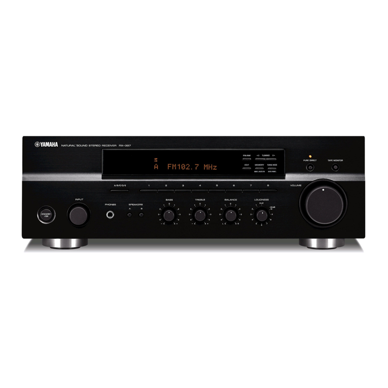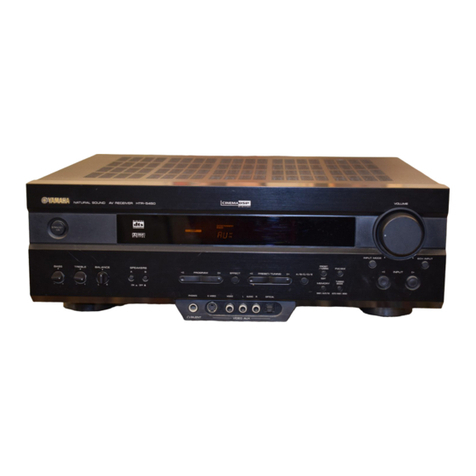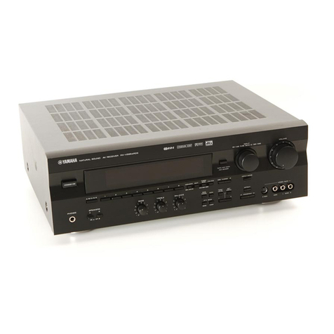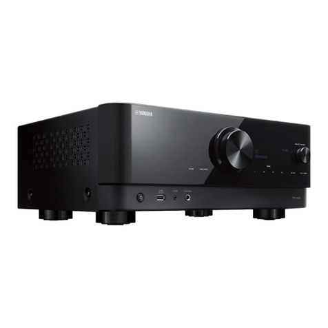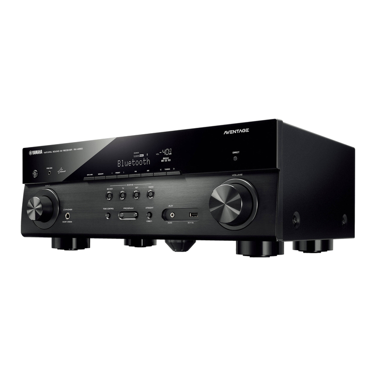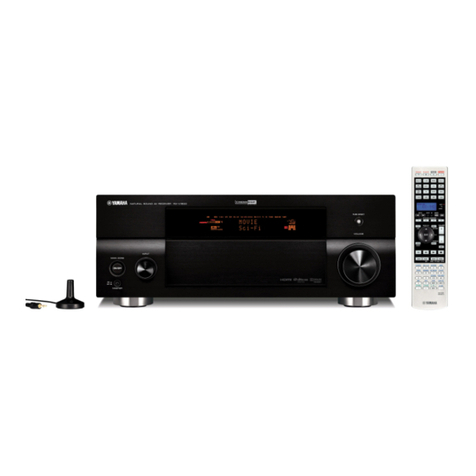
STEREO RECEIVER
RX-V1070/V870/V850
FIMPORTANT NOTICE ^
This manualhas been provided for the use ofauthorized YAMAHA Retailers andtheir service personnel.
Ithas been assumed that basic service procedures inherant to the industry,and more specifically YAMAHA
Products, are already known and understood by the users, and have therefore not beenrestated.
WARNING:Failureto follow appropriate service and safety procedures when servicing this product
may resultin personal injury,destructionofexpensive components and failureofthe
product to perform as specified. For these reasons, we advise all YAMAHA product owners
thatall service required should beperformed by an authorizedYAMAHARetaileror the
appointed service representative.
IMPORTANT: The presentation or saleof thismanualtoany individualor firmdoesnot constitute
authorization,certificationor recognitionof anyapplicable technical capabilities, or
establish a principle-agentrelationshipofany form.
The data provided isbelieved to beaccurate and applicable to the unit(s) indicated on the cover. Thereserch,
engineering, and service departments ofYAMAHAare continuallystrivingto improve YAMAHAproducts.
Modifications are, therefore, inevitable and specifications are subject to change withoutnotice or obligation to
retrofit. Should any discrepancy appear to exist, please contact the distributor'sService Division.
WARNING:Static discharges can destroy expensive components. Discharge any static electricity your
body may have accumulated by groundingyourself to the ground buss in theunit(heavy
gauge black wires connect to thisbuss).
IMPORTANT:
Turn the
unit
OFF
duringdisassembly and parts replacement. Recheck
all
work before
you
apply power to the unit.i
•
CONTENTS
——————
TOSERVICE PERSONNEL...........................................1
FRONTPANELS............................................................1
REARPANELS...............................................................2
SPECIFICATIONS......................................................3-4
BLOCK
DIAGRAM
.....................................................5-7
INTERNAL VIEW............................................................8
DISASSEMBLY
PROCEDURES
................................8-9
PROTECTIONFUNCTION...........................................10
ADJUSTMENTINPOWERAMPLIFIERSECTION....10
ADJUSTMENT INTUNERSECTION....................11-14
DIAGNOSTICOPERATION ...................................15-16
ICDATA..................................................................17-20
DISPLAY DATA............................................................21
PRINTEDCIRCUITBOARD ..................................22-41
WAVEFORM OFTESTPOINT..............................42-43
SCHEMATICDIAGRAM .........................................44-48
PARTS
LIST...........................................................49-78
REMOTECONTROL TRANSMITTER ...................79-80
