manuals.online logo
Brands
  1. Home
  2. •
  3. Brands
  4. •
  5. Yamaha
  6. •
  7. Stereo Receiver
  8. •
  9. Yamaha RX-V2600 User manual

Yamaha RX-V2600 User manual

OWNER'S MANUAL
CAUTION
RISKOFELECTRICSHOCK
,DONOTOPEN
CAUTION: TO REDUCE THE RISK OF
ELECTRIC SHOCK, DO NOT REMOVE
COVER (OR BACK). NO USER-SERVICEABLE
PARTS INSIDE. REFER SERVICING TO
QUALIFIED SERVICE PERSONNEL.
• Explanation of Graphical Symbols
Thelightning flash with arrowhead symbol,within an
equilateral triangle, is intendedm alert you to the
presence of uninsulaled "dangerous vohage" wilhin
the product's enclosure thai may be of sut]iciem
magnitude to constitutea risk of eleclric shock 1()
persolls,
The exclamation point within an equilateral triangle
is intended to alert you to tile presence of important
operating and mainmnancc/_lwicing) instructions in
the literature accompanying the appliance.
1 Read Instructions All the safety and operating instructions
should be read before the product is operated.
2 Retain Instructions The safety and operating instructions
should be retained for luture rel-ereuce.
3Heed Warnings All warnings on the product and in the
operating instructions should be adhered to.
4Follow Instructions All operating and use instructions
should be lk)llowed.
5 Cleaning Unplug this product li+(]mthe wall outlet belk_re
cleaning. Do not use liquid cleaners or aerosol cleaners.
6 Attachments Do not use attachments not recommended by
the product manulhcmrer as they may cause hazards.
7 Water and Moisture Do not use this product near water
for example, near a bath tub. wash bowl. kitchen sink. or
hmudry tub: in a wet basement: or near a swimming pool:
and the like.
8 Accessories Do not place this product on an unstable cart.
stand, tripod, bracket, or table. The product may fall.
causing serious it]iury to a child or adult, and serious
dmuage to the product. Use only with a cart. stand, tripod,
bracket, or table recommended by the manulhcturer, or sold
with the product. Any mounting of the product should
follow the manulhcturer's instructions, and should use a
mounting accessory recommeuded by the manufacturer.
9 A product and cart combination should be moved with care.
Quick stops, excessive lbrce, and uneven surlaces may
cause the product and cart combination to
overturn.
10 Ventilation Slots and openings in the cabinet are provided
lot ventilation and to ensure reliable operation of the
product and to protect it from overheating, and these
openings must not be blocked or covered. The openings
should never be blocked by placing the product on a bed.
solid, rug, or other similar surface. This product should not
be placed in a builtdn installation such as a bookcase or rack
unless proper ventilation is provided or the manufacturer's
instructions hme been adhered to.
11 Power Sources This product should be operated only from
the type of power source indicated on the marking label. If
you are not sure of the type of power supply to your home,
consult your product dealer or local power company. For
products intended to operate from battery power, or other
sources, refer to the operating instructions.
12 Grounding or Polarization This product may be equipped
with a polarized alternating current line phtg (a plug ha'dug
one blade wider than the other). This plug will lit into the
power outlet only one way. This is a safety feature. If you
are unable to insert the plug fully into the outlet, try
reversing the plug. If the plug should still fail to lit. contact
your electrician to replace your obsolete outlet. Do not
defeat the safety purpose of the polarized plug.
13 Power-Cord Protection Power-supply cords should be
routed so that they are not likely to be walked on or pinched
by items placed upon or against them, paying particular
attention to cords at plugs, convenience receptacles, and the
point where they exit from the product.
14 Lightning For added protection lot this product during a
lightning storm, or when it is left unattended and unused lk)r
long periods of time. unphtg it from the wall outlet and
disconnect the antenna or cable system. This will prevent
damage to the product due to lightning and power-line
surges.
1S Power Lines An outside antenna system should not he
located in the vicinity of overhead power lines or other
electric light or power circuits, or where it can fall into such
power lines or circuits. When installing an outside autmma
system, extreme cltre should be taken to keep from touching
such power lines or circuits as contact with them might be
latah
16 Overloading Do not overload wall outlets, extension
cords, or integral convenience receptacles as this can result
in a risk of fire or electric shock.
17 Ot)ject and Liquid Entry Never push objects of any kind
into this product through openings as they may touch
dangerous voltage points or short-out parts that could result
in a fire or electric shock. Never spill liquid of any kind on
the product.
18 Servicing Do not attempt to service this product yourself
as opening or removing covers may expose you to
dangerous voltage or other hazards. Reli:r all servicing to
qualified service personneh
19 Damage Requiring Service Unplug this product from the
wall outlet and reli:r servicing to qualified service personnel
under the lollowiug conditions:
a) When the power-supply cord or plug is damaged,
b) If liquid hits been spilled, or objects haxe fallen into the
product.
c) If the product hits been exposed to rain or water.
2O
22
d) If the product does not operate normally by following
the uperating instructions. Adjust uuly those controls
that are covered by the operating instructions as an
improper adjustment of other controls may result in
damage and will often require extensive work by a
qualified technician to restore the pruduct to its normal
operation.
el If the product has been dropped or damaged in any
way, and
f) When the product exhibits a distinct change in
performance - this indicates a need for service.
Replacement Parts When replacement parts are required.
be sure the service technician has used replacement parts
specified by the mauulhcturer or haxe the same
characteristics as the urigiual part. Unauthorized
substitutions may result in fire. electric shock, or other
hazards.
Safety Check Upon completion of any service or repairs to
this product, ask the service technician to perform sali_ty
checks to determine that the pruduct is in proper operating
condition.
Wall ur Ceiling Mounting The unit should be mounted
to a wall or ceiling only as recommended by the
maRul'acturer.
23 Heat The product should be situated away fi'om heat
sources such as radiators, heat registers, stuves, ur other
products (including amplifiers) that produce heat.
24 Outdoor Antenna Grounding If an outside antenna or
cable system is connected tu the product, be sure the antmma
or cable system is grounded so as to provide some
protection against voltage surges and built-up static charges.
Article 810 of the National Electrical Code. ANSI/NFPA 70.
provides informatiuu with regard to proper grounding of the
mast and supporting structure, grounding of the lea&in wire
to an antenna discharge unit. size of grounding cunductors.
locatiun of antenna discharge unit. cunuection to grounding
electrudes, and requirements for the grounding electrode.
EXAMPLE OF ANTENNA GROUNDING
Note to CATV system installer:
This reminder is provided to call the CATV system
installer's attention to Article 820-40 of the NEC that
provides guidelines for proper grounding and, in
particular, specifies that the cable ground shall be
connected to the grounding system of the buikting, as
close to the point of cable entry as practical.
NEC NATIONAL ELECTRICALCODE
FCC INFORMATION (for US customers)
1IMPORTANT NOTI(-E: DO NOT MODIFY THIS
UNIT!
This product, when installed as indicated in the
instructions cuntained in this manual, meets FCC
requirements. Modificatiuns not expressly approved by
Yamaha may void yuur authority, granted by the FCC. to
use the product.
IMPORTANT: When connecting this product to
accessuries and/or another pruduct use only high quality
shielded cables. Cablc/s supplied with this product MUST
be used. Follow all installation instructions. Failure to
fl)llow instructions could void your FCC authorization tu
use this pruduct in the USA.
NOTE: This product has been tested and found to comply
with the requirements listed in FCC Regulations. Part 15
li)r Class "B" digital devices. Compliance with these
requirements provides a reasonable level uf assurance thai
your use of this product in a residential environment will
not result in harmfid interference with other electrunic
devices.
This equipment generates/uses radio li'equencies and. if
not installed and used according to the instructions fuund
in the users manual, may cause interference harmlM to the
operation of other electronic devices.
Compliance with FCC regulations does not guarantee that
interli_rence will not uccur in all installations. If this
product is louud to he the source of interference, which
can be determined by turning the unit "OFF" and "ON".
please try to eliminate the problem by using one of the
following measures:
Relocate either this product or the device that is being
affected by the interlerence.
Utilize puwer outlets that are on dilti_rent branch (circuit
breaker ur fllse) circuits or install AC line filter/s.
In the case of radio or TV interference, relucate/reurient
the antenna. If the antenna lead-in is 300 uhm ribbon lead.
change the leadqn to cuaxial type cable.
If these corrective measures do not produce satislactory
results, please contact the lucal retailer mlthorized to
distribute this type of product. If you can not locate the
appropriate retailer, please contact Yamaha Electrunics
Corp.. U.S.A. 6660 Orangethurpe Ave. Buena Park. CA
90620.
The above statements apply ONLY to those products
distributed by Yamaha ( orporation of America or its
subsidiaries.
1 Toassurethefinestperformance,pleasereadthismanual
carefully.Keepitinasafeplaceforfuturereference.
2 Installthissoundsysteminawellventilated,cool.dry,clean
placeawayt'rom direct sunlight, heat sources, vibration.
dust. moisture, and/or cold. Allow ventilation space of at least
30 cm on the top, 20 cm on the lell and right, and 20 cm on
the back of this unit.
3Locate this unit away from other electrical appliances, motors.
or transformers to avoid humming sounds.
4 Do not expose this unit to sudden temperature changes I?om
cold to hot. attd do not locate this unit in art mwironment with
high humidity (i.e. a room with a humidifier) to prevent
condensation inside this unit. which may cause an electrical
shock, fire. damage to this unit. and/or personal injury.
5 Avoid installing this unit where loreigu ohjects may fall onto
this unit and/or this unit may be exposed to liquid dripping or
splashing. On the top of this unit. do not place:
Other components, as they may cause damage and/or
discoloration on the surface of this unit.
Burning ot_jects (i.e. candles), as they may cause fire.
damage to this refit, attd/or personal injury.
Contaioers with liquid in them. as they may fall and liquid
may cause electrical shock to the user and/or damage to
this unit.
6 Do not cover this unit with a newspaper, tablecloth, curtain.
etc. in order not to obstruct heat radiation. If the temperature
inside this unit rises, it may cause fire. damage to this unit.
and/or personal il_jury.
7 Do not plug in this unit to a wall outlet tmtil all connections
are complete.
8 Do not operate this unit upside-down. It may overheat.
possibly causing damage.
9 Do not use lorce on switches, knobs and/or cords.
10 When discommcting the power cable from the wall outlet.
grasp the plug; do not pull the cable.
11 Do not clean this trait with chemical solvents: this might
damage the finish. Use a clean, dry cloth.
12 Only voltage specified on this unit must be used. Using this
unit with a higher voltage than specified is dangerous and may
cause fire. damage to this unit. attd/or personal injury.
YAMAHA will not be held responsible for any damage
resulting fi'om use of this unit with a voltage other than
specified.
13 To prevent damage by lightning, keep the power cord and
outdoor antennas disconnected from a wall outlet or the unit
during a lightning storm.
14 Do not attempt to modil} or fix this unit. Contact qualified
YAMAHA service personnel when any service is needed. The
cabinet should never be opened lk_rarty reasons.
15 When not plamting to use this unit fiw long periods of time
(i.e. vacation), disconnect the AC power plug lhom the wall
outlet.
16 Install this unit near the AC outlet and where the AC power
plug can be reached easily.
17 Be sure to read the "TROUBLESHOOTING" section on
common operating errors before concluding that this unit is
faulty.
18 Belore moving this unit, press MASTER ON/OFF to release it
outward to the OFF position to turn off this unit. the main
room. Zone 2 and Zone 3 and then disconnect the AC power
plug lhom the AC wall outlet.
WARNING
TO REDUCE THE RISK OF FIRE OR ELECTRIC
SHOCK, DO NOT EXPOSE THIS UNIT TO RAIN
OR MOISTURE.
As long as this unit is connected to the AC wall outlet,
it is not disconnected from the AC power source even
if yon turn offthis unit by MASTER ON/OFF. In this
state, this unit is designed to consume a very small
quantity of po'a, er.
FOR CANADIAN CUSTOMERS
To prevent electric shock, match wide blade of plug to
wide slot and fully insert.
This Class B digital apparatus complies with Canadian
ICES-003.
POUR LES CONSOMMATEURS CANADIENS
Pour (viter les chocs (lectriques, introduire la lan]e la
plus large de la fiche dans la borne correspondante de
la prise et ponsser jusqu'au fond.
Cet appareil num(rique de la classe Best conforme :5
la norme NMB-003 du Canada.
IMPORTANT
Please record the serial number of this unit in the space
below.
MODEL:
Serial No.:
The serial number is located on the rear of the unit.
Retain this Owner's Manual in a safe place for future
reference.
We Want You Listening For A Lifetime
YAMAHA :rod the Electronic Industries Associations Consumer Electronics Group want you to getthe most out of )our
equipment b) playing it at asafe leveh One that letsthe sound come through loud:rod dear without amtoying blaring or
distortion and. most importantl), without affecting your sensitive he:wing. Sittce hearing damage l?om loud sounds is
often undetectable until it is too late. YAMAHA and the Electronic Industries Association's Consumer Electronics Group
reconlmend you to avoid prolollged exposure from excessive vo]unle levels.
iii
LISTENING
FEATURES ............................................................. 2
GETTING STARTED ............................................ 3
Supplied accessories .................................................. 3
Installiog batteries in the remote controls .................. 4
Handling the remote control ...................................... 5
Opening and closing the front panel door .................. 5
CONTROLS AND FUNCTIONS ......................... 6
Front panel ................................................................. 6
Remote control ........................................................... 8
Zone 2/Zone 3 remote control ................................. 10
Front panel display .................................................. 11
Rear panel ................................................................ 13
CONNECTIONS .................................................. 14
Before connecting speakers ..................................... 14
Connecting speakers ................................................ 15
Using bi-wire and bi-AMP connections .................. 19
Information on cables and jacks
used liw connections ............................................ 20
Commcting HDMI components ............................... 23
Commcting video components ................................. 24
Connecting audio components ................................. 27
Connecting the antennas .......................................... 29
Commcting the power cable ..................................... 30
Turning on and off this unit ..................................... 30
Setting the speaker impedance ................................. 31
AUTO SETUP ....................................................... 32
Introduction .............................................................. 32
Optimizer microphone setup .................................... 32
Using AUTO SETUP .............................................. 33
Confirming the results ............................................. 35
PLAYBACK .......................................................... 37
Basic operations ....................................................... 37
Additional operations ............................................... 39
RECORDING ....................................................... 46
FM/AM TUNING ................................................. 47
Automatic tuning ..................................................... 47
Manual tuning .......................................................... 48
Automatic preset tuning ........................................... 48
Manual preset tuning ............................................... 50
Selecting preset stations ........................................... 51
Exchanging preset stations ...................................... 52
XM® SATELLITE RADIO TUNING ............... 53
What is XM Satellite Radio'? ................................... 53
XM Satellite Radio connections .............................. 53
XM Satellite Radio controls and lm]ctions .............. 54
Activating XM Satellite Radio ................................ 55
Selecting the XM Satellite Radio mode ................... 56
Using XM Satellite Radio search modes ................. 57
Setting XM Satellite Radio preset channels ............ 60
Displaying the XM Satellite Radio
information .......................................................... 62
m
EDITING SOUND FIELD PARAMETERS ...... 63
What is a sound field? ............................................. 63
Changing parameter settings ................................... 63
SOUND FIELD PROGRAM
DESCRIPTIONS ............................................... 65
For movic/video sources .......................................... 65
For music sources .................................................... 67
SOUND FIELD PARAMETER
DESCRIPTIONS ............................................... 68
SOUND FIELD PROGRAM
SPEAKER LAYOUTS ...................................... 73
m
SYSTEM OPTIONS ............................................. 77
Changing parameter settings ................................... 79
Input Select .............................................................. 80
Manual Setup (Sound) ............................................. 83
Manual Setup (Video) ............................................. 87
Manual Setup (Basic) .............................................. 90
Manual Setup (Option) ............................................ 94
System Memory ....................................................... 99
Language ............................................................... 100
ADVANCED SETUP .......................................... 101
Using ADVANCED SETUP ................................. 101
REMOTE CONTROL FEATURES ................. 103
Control area ........................................................... 103
Controlling each component .................................. 104
Setting remote control codes ................................. 105
Using LEARN ....................................................... 107
Using RE-NAME .................................................. 109
Using MACRO ...................................................... 110
Using CLEAR ........................................................ 112
ZONE 2/ZONE 3 ................................................. 115
Connecting the Zone 2 and
Zone 3 components ........................................... 115
Selecting Zone 2 or Zone 3.................................... 116
Controlling Zone 2 and Zone 3 .............................. 117
Using the control mode of
Zone 2 and Zone 3 ............................................. 118
HDMI ................................................................... 119
What is HDMI? ..................................................... 119
Setting the HDMI parameters ................................ 120
Basic HDMI operations ......................................... 120
TROUBLESHOOTING ..................................... 121
GLOSSARY ......................................................... 128
Audio inf_rmation ................................................. 128
Video information .................................................. 13l
Sound field program inlormation .......................... 131
Parametric equalizer information .......................... 132
SPECIFICATIONS ............................................. 133
Built-in 7-channel power amplifier
• Minimum RMS Output Power
(0.04% THD, 20 Hz to 20 kHz, 8 _Q)
Front: 130 W + 130 W
Center: 130 W
Surround: 130 W + 130 W
Surround Back: 130 W + 130 W
Sound field features
• Proprietary YAMAHA technology for the creation of
sound fields
• THX Select2
• Dolby Digital/Dolby Digital EX decoder
• DTS/DTS-ES Matrix 6.1, Discrete 6.1,
DTS Neo:6 decoder, DTS 96/24
• Dolby Pro Logic/Dolby Pro Logic lix decoder
• Virtual CINEMA DSP
• SILENT CINEMA TM
HDMI (High-Definition Multimedia Interface)
• HDMI interface t_r standard, enhauced or
high-definition video as well as multi-channel digital
audio
• Analog video to HDMI digital video up-conversion
(composite vkteo +_ S-video <_.component video :_
HDMI digital video) and up-scaling (480i _ 480p1
1080i1720p and 480p > 1080i1720p) capabilities for
monitor out
Sophisticated AM/FM tuner
• 40-station random access preset tuning
• Automatic preset tuning
• Preset station shitting capability (preset editing)
XM Satellite Radio (U.S.A. model only)
• XM Satellite Radio tuning capability
Other features
• YPAO (YAMAHA Parametric Room Acoustic
Optimizer) for automatic speaker setup
• 192-kHz/24-bit D/A converter
• GUI (graphical user interface) menus that allow you to
optimize this unit to suit your individual audio/video
system
• GUI display menu hmguage switching capability
(English, Japanese, French, German and Spanish)
• 6 or 8-channel additional input jacks for discrete
nmlti-channel input
• Short message function
• PURE DIRECT for pure fidelity sound with analog and
PCM sources
• S-video input/output capability
• Component video input!output capability
• Analog video I/P conversion from 480i to 480p
• Optical and coaxial digital audio signal jacks
• Sleep timer
• Cinema and music night listening mode
• Remote control with preset remote control codes and
learning/macro capability
• Zone 2/Zone 3 custom installation facility
• Zone 2/Zone 3 remote control to control Zone 2 or
Zone 3
• Zone 20SD (on-screen display) capability
• -"4;'-indicates a tip lor your operation.
• Sonm operations can be performed by using either the buttons on the main unit or on the remote controh In cases when the button
names difli:r hetween the main unit and the remote control, the button nanm on the remote control is given in parentheses.
• This manual is printed prior to production. Design and specifications are subject to change in part as a result of improvements, etc.
111case of dilti_rences between the manual and product, the product has priority.
DIGiTAL, EX
Mauuf:_ctured under license from Dolby Laboratories.
"Dolby". "Surround EX'. and the double-D symbol are
trademarks of Dolby Laboratories.
"DTS'. "DTS-ES'. "Neo:6" and "DTS 96/24" are trademarks of
Digital Theater Systmns. Inc.
"HDMI'. the "HDMI" logo and "High-Definition Multimedia
Interface" are trademarks or registered trademarks of HDMI
Licensing LLC.
SILENT "
CINEMA
"SILENT CINEMA" is a trademark of YAMAHA
CORPORATION.
TAx
The THX logo is a trademark of THX Ltd. which inW be
registered in some jurisdictions. All rights reserved.
REAOY
_) 2005 XM Satellite Radio Inc. All rights reserved. All other
trademarks are the property of their respective owners.
Pleasecheckthatyoureceivedallofthefollowingparts.
Remote control
Zone 2/Zone 3
remote control
Batteries (x6)
(AAA, LR03)
Power cable Speaker terminal
wrench Optimizer microphone
AM loop antenna Indoor FM antenna
• Change all of the batteries if you notice conditions such as the operation range of the remote control decreases, the indicator does not
flash, or its light or display window become dim.
• [)(7not use old batteries together with new ones.
• [)(7not use dilfcrent types of batteries (such as alkaline and manganese batteries) together. Read the packaging carekdly as these
dilTerent types of batteries may have the same shape and color.
• We strongly recommend using alkaline batteries.
• If the batteries hm'e leaked, dispose of them immediately. Avoid touching the leaked material or letting it come into contact with
clothing, etc. Clean the battery compartment thoroughly before installing new batteries.
• Do not throw away batteries with general house waste: dispose of them correctly in accordance with your local regulations.
•Installing batteries •Zone 2/Zone 3 remote control
Press the _part and slide the battery
compartment cover off.
1 Press the _part and slide the battery
compartment cover off.
2Insert four supplied batteries
(AAA, LR03) according to the polarity
markings on the inside of the battery
compartment.
3 Slide the cover back until it snaps into place.
Insert two supplied batteries (AAA, LR03)
according to the polarity markings (+ and -)
on the inside of the battery compartment.
3 Slide the cover back until it snaps into place.
If the remote control is without batteries for more than
2 minutes, or if exhausted batteries remain in the
remote control, the contents of the memory may be
cleared. When the memory is cleared, insert new
batteries, set up the remote control code and program
any acquired fimctions that may have been cleared.
Theremotecontroltransmitsadirectionalinfraredray.
Besuretoaimtheremotecontroldirectlyattheremotecontrolsensoronthemainunitduringoperation.
Approximately 6 m (20 ft) _30[
•Do not spill water or other liquids on the remote control.
• Do not drop the remote control.
• Do not leave or store the remote control in the lkHlowing types of conditions:
places of high humidity, such as near a bath
places of high temperatures, such as near a heater or stove
extremely low temperatures
dusty places
When you want to use the controls behind the front panel door, open the door by gently pressing on the lower part of the
panel. Keep the door closed when not using these controls.
To open, press gently on the lower part of the panel.
The XM Satellite Radio controls (SEARCH MODE, CATEGORY. PRESET/TUNING/CH <11 C:>. MEMORY and DISPLAY) are only
applicable lo the U.S.A. model and are operational only when XM is selected as Ihe inpul source. For details, see "Front panel
fl]nclions" on page 54.
1¸-
_)YANNt
===:= ........................ ==: ...........................
F
{--
5============
(U.S.A. model)
@MASTER ON/OFF
Press inward to the ON position.
• Turns on this unit.
• Turns on the main room.
• Sets Zone 2 and Zone 3 to the standby mode.
Press again to release it outward to the OFF position.
• Turns off this unit.
• Turns off the main room, Zone 2 and Zone 3.
See page 30 for details.
@MAIN ZONE ON/OFF
Tnrns on this unit only or sets it to the standby n]ode.
In the standby mode. this unit consumes a small quantity of
power.
•When you turn on this unit. there will be a h to 7 second delay
before this unit can reproduce sound.
• This button is operational only when MASTER ON/OFF is
pressed inward to the ON position.
@INPUT selector
Selects the desired input source.
@AUDIO SELECT
Toggles the priority for the type of audio input jack
between AUTO, HDMI, COAX/OPT and ANALOG when
one component is connected to two or more input jacks on
the rear panel (see page 44).
@MULTI CH INPUT
Selects the input source connected to the MULTI CH
INPUT jacks. When selected, the MULTI CH INPUT
source takes priority over the input source selected with
the INPUT selector (or the input selector buttons on the
remote control).
@A/B/C/DIE
Selects one of the 5 preset station groups (A to E) when
TUNER is selected as the input source (see page 51).
@PRESET/TUNING/CN <_ /E>
Selects the preset station number (1 to 8) when TUNER is
selected as the input source and the colon (:) is displayed
next to the band indication in the front panel display.
Selects the tuning frequency when TUNER is selected as
the input source and the colon (:) is not displayed in the
front panel display.
See pages 47 to 52 for details.
@Front panel display
Sho'a,s information about tile operational status of this
unit.
@PRESET/TUNING (EDIT)
Switches tile function of PRESET/TUNING/CH <1/C>
between selecting preset station numbers and tuning when
TUNER is selected as the input source (see pages 47 to
52).
@FM/AM
Switches tile reception band (FM or AM) when TUNER is
selected as the input source (see page 47).
The frequm/cy of the previously received station is automatically
recalled.
@MEMORY (MAR'L/AUTO FM)
Stores a station in the memory when TUNER is selected
as the input source. HoLt down for more than 3 seconds to
start automatic preset tuning (see page 48).
@TUNING MODE (AUTO/MAR'L), DISPLAY
Switches the tuning mode between automatic (the AUTO
indicator is turned on) and mannal (the AUTO indicator is
turned oft') when TUNER is selected as the input source.
STRAIGHT (EFFECT)
Turns the sound field programs on or oft'. When
STRAIGHT is selected, 2-channel or multi-channel input
signals are output directly from the respective speakers
without effect processing.
@Remote control sensor
Receives infrared signals from the remote controh
@TONE CONTROL
Use to adjust tile balance of bass and treble for the front
left and right and center channels (see page 39).
_PURE DIRECT
Turns on or off the PURE DIRECT mode (see page 42).
The indicator around the button lights up when the unit is in the
PURE DIRECT mode.
@REC OUT/ZONE 2
Selects the input source you "a,ant to direct to the audio/
video recorder and Zone 2 outputs independently of the
input source you are listening to or watching in the main
room. When set to the SOURCE/REMOTE position, the
input source is directed to all outputs.
The Zone 2 output is always identical with the input source you
record.
e.leldll;[el_.'JF_qdlel_#ld[e.*J#[eldg
@OPTIMIZER MIC jack
Use to connect the supplied optimizer microphone to run
AUTO SETUP (see page 32).
@SPEAKERS MB
Turn on or off the set of front speakers connected to the
SPEAKERS A and/or B terminals on the rear panel each
time the corresponding button is pressed.
@(-_ PHONES (SILENT CINEMA) jack
Ol.ltputs audio siguals for private listeniilg with
headphones.
• When you connect headphones, no signals arc output at the
PRE OUT jacks or to the speakers.
• All Dolby Digital and DTS audio signals are mixed down to 2-
channel stere() (front left and right channels).
@VIDEO AUX jacks
Input audio and video signals from an external source such
as a game console. To reproduce source signals at these
jacks, select V-AUX as the input source.
@MULTI ZONE buttons
ZONE 2 ON/OFF
Turns on Zone 2 only or sets it to the standby mode.
See page 30 t_r details.
This button is operational only when MASTER ON/OFF is
pressed inward to the ON position.
ZONE 3 ON/OFF
Turns on Zone 3 only or sets it to tile standby mode.
See page 30 for details.
This button is operational only when MASTER ON/OFF is
pressed inward to the ON position.
ZONE CONTROL
Switches tile zone you "a,:tnt to control between the
main unit, Zone 2 and Zone 3 (see page 117).
After you press ZONE CONTROL, the indicator for
the currently selected zone flashes in the front panel
display for approximately 5 seconds. While the
indicator is flashing, perform the desired operation.
@PROGRAM selector
Use to select sound field programs or adjust the balance of
bass and treble in conjunction with TONE CONTROL.
@VOLUME
Controls tile volume level of :tll audio channels.
This does not affect the OUT (REC) level.
Thissectiondescribesthefimctionofeachcontrolonthe
remotecontrolnsedtocontrolthisunit.SetAMP/
SOURCE/TVtoAMPtooperatethisunit.Tooperate
othercomponents,see"REMOTECONTROL
FEATURES"onpage103.
TheXMSatelliteRadiocontrols(XM,XMMEMORY,SRCH
MODE,DISPLAY,cursorbuttonsA/V/<3 /c>, nmneric
buttons and ENT.) are unly applicable to the U.S.A. model and
are operational only when XM is selected as the input source. For
details, see "Rmnote control l]mctions" on page 54.
_TEREO MUSIC ENTERTAIN _aOVlE
q9 (D (P O
Sq'A_IC*ARt_ SELECT E×TOSU_
(P (D (D
I I .......................
_J @YANARA
(U.S.A.model)
............,_
@Infrared window
Outputs infrared control signals. Aim this windo'a, at the
component you want to operate.
@Transmission indicator
Flashes "a,hile the remote control is sending infrared
signals.
@Input selector buttons
Select the inpnt source and ctmnge the control area.
Set AMP/SOURCE/TV to SOURCE and then press
TUNER to select TUNER as the input source.
Set AMP/SOURCE/TV to SOURCE and then press XM
to select XM as the input source.
@Display window
Shows the name of the selected input source that you can
control.
@Light button
Press to light up the remote control buttons and the display
window.
@GUI TOP, BAND
Displays the top screen in the graphical user interface
(GUI) menu on your video monitor when AMP/SOURCE/
TV is set to AMP.
Switches the reception band between FM and AM when
AMP/SOURCE/TV is set to SOURCE and TUNER is
selected as the input source.
@ Cursor buttons !X /g/<1 /1>, ENTER
Selects and adjusts the DSP program parameters or GUI
menu items when AMP/SOURCE/TV is set to AMP.
Press <3 /C:>to select a preset station group (A to E) and
A/V to select a preset station nnmber (1 to 8) when
AMP/SOURCE/TV is set to SOURCE and TUNER is
selected as the input sonrce.
@Sound field program /numeric buttons
Select sound field programs vdlen AMP/SOURCE/TV is
set to AMP.
Use SELECT to play back 2-channel sources in the multi-
channel format (see page 41).
Use EXTD SUR. to switch between 5.1 and 6.1/7.1
channel playback of multi-channel software (see page 40).
Use numbers 1 to 8 to select preset stations when AMP/
SOURCE/TV is set to SOURCE and TUNER is selected
as the input source.
@MEMORY 112
Use to recall fav*orite sonnd fieM progranls, YPAO settings
or additional preset stations (see page 99).
@MACRO ON/OFF
Turns on or oft" the macro function (see page 111 ).
@MACRO
Programs a series of operations to be controlled with :t
single button (see page 110).
@STANDBY
Sets this unit, Zone 2 and Zone 3 to the standby mode (see
page 30).
This button is operational only when MASTER ON/OFF on the
front panel is pressed inward to the ON position.
@POWER
Turns on this unit, Zone 2 and Zone 3 (see page 30).
This button is operational only when MASTER ON/OFF on the
lront panel is pressed inward to the ON position.
_a) AUDIO SEL
Toggles the priority for tire type of audio input jack
between AUTO, HDMI, COAX/OPT and ANALOG when
one component is connected to two or more input jacks on
the rear panel (see page 44).
SLEEP
Sets tire sleep timer.
@MULTI CH IN
Selects MULTI CH INPUT "a,hen using an external
decoder, etc.
SELECT A/g
Selects another input source that you can control
independently of the input source selected with the input
selector buttons.
@VOLUME +/-
Increasesor decreases tire volume level.
@AMP/SOURCE/TV
Selects the cornponent you "a,ant to control with tire
relnote control.
AMP
Set to this position to operate this unit.
SOURCE
Set to this position to operate tire component selected with
an input selector button.
TV
Set to this position to operate the television assigned to
either DTV or PHONO.
_e],Vll;£e]_._Jr:y,Vel_#J,V[e.*J#[e],vg
If televisions are assigned to both DTV and PHONO, the one
assigned to DTV takes priority and gets operated when AMP/
SOURCE/TV is set to TV.
To set the remote control codes lot other conlponents, see
page 105.
_MUTE
Mutes tire sound. Press again to restore tire andio output to
the previous volume level.
@PURE DIRECT
Turns on or off the PURE DIRECT mode (see page 42).
;_ EXIT
Exits the GUI mode.
@NIGHT
Turns on or off the night listening modes (see page 42).
STRAIGHT (EFFECT)
S'a,itches tire sound field programs off or on. When
STRAIGHT is selected, 2-channel or nmlti-channel input
signals are output directly from their respective speakers
without effect processing.
@SPEAKERS A/B
Turns on or off the set of front speakers connected to tire
SPEAKERS A and/or B terminals on the rear panel each
time the corresponding button is pressed.
@RE-NAME
Changes the name of the input source in tire display
window (see page 109).
;_ CLEAR
Clears remote control codes or functions acquired from
the learn, macro and rename features (see page 112).
LEARN
Programs remote control codes or functions from other
remote controls (see page 107).
ThissectiondescribestheErectionofeachcontrol on the
Zone 2/Zone 3 remote control used to control Zone 2 or
Zone 3.
The XM Satellite Radio controls (XM. DISPLAY. PRESET.
ALL. CAT.. numeric buttons. NUMBER. cursor buttons
A/V/<:_/12>and ENT) are only applicable to the U.S.A. model
and are operational only when XM is selected as the input source.
For details, see "Zone 2/Zone 3 remote control Erections" on
page 55.
A/B/e/D/E
....,,,,_5
........,,_
(U.S.A. model)
@Input selector buttons
Select the desired input source of Zone 2 or Zone 3 and
change the control area.
PRESET +/-
Selects tile preset station nnlnber (1 to 8) when TUNER is
selected as the input source or Zone 2 or Zone 3.
@AIBIC/D/E
Selects the preset station group (A to E) "a,hen TUNER is
selected as the input source or Zone 2 or Zone 3.
@IDI/ID2 switch
S'a, itches the remote control ID between IDI and ID2
(see page 106).
_5 POWER
Turns on Zone 2 or Zone 3.
This button is operational only when MASTER ON/OFF on the
front panel is pressed inward to the ON position.
@STANDBY
Sets Zone 2 or Zone 3 to tile standby mode.
This button is operational only when MASTER ON/OFF on the
front panel is pressed inward to the ON position.
@VOLUME +/-
Increases or decreases the volume level or Zone 2 or
Zone 3.
@MUTE
Mutes the sound of Zone 2 or Zone 3.
Press again to restore the audio outpnt to the previous
volume level.
@ZONE 2/ZONE 3 switch
Sw,itches between tile operation mode of Zone 2 and that
of Zone 3.
10
_e]dll;{e]J_'JP_qdlel_lJd[e_Jl[e]dA
The XM indicator is only applicable to the U.S.A. model.
@YPAO indicator
Lights up when the AUTO SETUP procedure is in
progress and when the AUTO SETUP speaker settings are
used without any modifications.
@HDMI indicator
Lights up when HDMI components are assigned to the
HDMI IN 1 and HDMI IN 2 jacks and they are recognized
by this unit.
Turns off when no HDMI component is assigned to the
either HDMI IN 1 or HDMI IN 2jack or when no HDMI
component is recognized by this unit althongh they are
assigned to the HDMI IN jacks.
See page 119 for details.
@CINEMA DSP indicator
Lights up when you select a CINEMA DSP sound field
program.
@Decoder indicators
When any of the decoders of this unit operate, the
respective indicator lights up.
@Input source indicators
Light up "a,hen the corresponding input source is selected.
@VOLUME level indicator
Indicates the vohnne leveh
@MUTE indicator
Flashes while the MUTE flmction is on.
@AUTO indicator
Lights up when this unit is in the automatic tuning mode.
@STEREO indicator
Lights up "a,hen this unit is receMng a stereo signal for an
FM stereo broadcast while the AUTO indicator is lit.
@TUNED indicator
Lights up when this unit is tuned into a station.
@MEMORY indicator
Fhtshes to indicate that a station can be stored.
@Headphones indicator
Lights up when headphones are connected.
@SILENT CINEMA indicator
Lights up when headphones are connected and a sonnd
fiekt program is selected (see page 39).
@SP A B indicators
Light up according to tile set of front speakers selected.
Both indicators light up when both sets of front speakers
are selected or when bi-wiring.
@VIRTUAL indicator
Lights up when Virtual CINEMA DSP is active
(see page 44).
@Sound field indicators
Light up to indicate tile active DSP sound fields.
Presence DSP sound field
J
_-, _ Lislenin_ position
Le s[r)tnc i\,\ 7, :_R_I s[") c
DSP sound held DSP sound held
Surround/surround back DSP sound field
@HiFi DSP indicator
Lights up when you select a HiFi DSP sound field
program.
@PCM indicator
Lights up when this unit is reproducing PCM (pulse code
modulation) digital audio signals.
@DSD indicator
Lights up when this unit is reproducing DSD (direct
stream digital) digital audio signals.
@Multi-information display
Shows the name of tile cnrrent sonnd field progranl and
other information when adjusting or changing settings.
11
@96/24 indicator
Lights up when a DTS 96/24 signal is input to this unit.
_LFE indicator
Lights up when tile input signal contuins an LFE signal.
@Input channel and speaker indicators
Input channel indicators
Indicate the channel components of the current digital
input signal.
g3_
Presence and surround back speaker
indicators
Light up according to the number of presence and
surround back speakers set for Presence (see page 92)
and Surround Back (see page 91 ) in Manual Setup
when Test Tone in Manual Setup is set to On (see
page 90).
Yuu can make settings fur the presence and surround back
speakers automatically by running Auto Setup (see page 32)
or manually by a_[iusting settings fur Presence (see page 92)
and Surround Back (see page 91) in Manual Setup.
@NIGHT indicator
Lights up when you select a night listening mode.
@SLEEP indicator
Lights up "a,hile the sleep timer is on.
@ZONE 2/ZONE 3 indicators
Light up when Zone 2 or Zone 3 is turned on.
12
_l]_TiI;{I]ik'JF:hqll_lJ_T[ell[I]_Tt.
(U.S.A. model)
@DIGITAL OUTPUT jacks
See pages 24, 25 and 27 for connection intbrmation.
@DIGITAL INPUT jacks
See pages 24, 25 and 27 for details.
@Video component jacks
See pages 24 and 25 for connection information.
@Audio component jacks
See pages 24, 25 and 27 t_r connection information.
@CONTROL OUT jacks
These are control expansion terminals for factory use only.
@WRENCH HOLDER
Use to hook tile supplied speaker terminal "a,rench when
not in use (see page 16).
@Antenna terminals
See page 29 for connection information.
@AC OUTLETS
Use to supply pow,er to your other A/V components
(see page 30).
@AC IN
Use this inlet to plug ill tile supplied pow, er cable
(see page 30).
@XM jack (U.S.A. model only)
See page 53 for connection infommtion.
@HDMI IN/OUT connectors
See page 119 for connection information.
@RS-232C terminal
This is a control expansion ternlinal for factory use only.
Consult you dealer for details.
@ZONE 2/ZONE 3 OUTPUT jacks
See page 115 for details.
@MULTI CH INPUT jacks
See page 26 for connection information.
@PRE OUT jacks
See page 28 for connection int_rmation.
@REMOTE 112 IN/OUT jacks
See page 115 for details.
@Speaker terminals
See page 15 for connection information.
@PRESENCE/ZONE 2(3) speaker terminals
See page 17 for connection infommtion.
13
The speaker layout below shows the standard ITU-R*
speaker setting. You can use it to enjoy CINEMA DSP,
multi-channel audio sources and THX.
* ITU-R is the radio communication sector of the ITU
(International Tclec()mmunication Union).
30 +
More than 30 cm (12 in)
Surround speakers (SR and SL)
Tile surround speakers are used for effect and surround
sounds. Place these speakers behind your listening
position, facing slightly inwards, about 1.8 m (6 It) above
the floor.
Surround back speakers (SBR and SBL)
The surround back speakers supplement the surround
speakers and provide for more realistic front-to-back
transitions. Place these speakers directly behind the
listening position and at the same height as the surround
speakers. They should be positioned at least 30 cm (12 in)
apart. Ideally, they shoukt be positioned at the same width
as the front speakers.
Subwoofer
The use of a subwoofer, such as the YAMAHA Active
Servo Processing Subwoofer System, is effective not only
for reinforcing bass frequencies from any or all channels,
but also for high fidelity reproduction of the LFE (low-
frequency effect) channel included in Dolby Digital and
DTS software. The position of the subwoofer is not so
critical, becanse low bass sounds are not highly
directional. But it is better to place the subwoofer near the
front speakers. Turn it slightly toward the center of the
room to reduce wall reflections.
Presence speakers (PR and PL)
Presence speakers supplement the sound from the front
speakers with extra ambient effects produced by CINEMA
DSP (see page 65). These effects include sounds that
filmmakers intend to locate a little farther back behind the
screen in order to create more theater-like ambience. Place
these speakers at the front of the room about 0.5 1 in
(1 3 ft) outside the front speakers, facing slightly
inwards, and about 1.8 in (6 ft) above the floor.
Front speakers (FR and FL)
The front speakers are used for the main source sound plus
effect sounds. Place these speakers an equal distance from
the ideal listening position. The distance of each speaker
from each side of the video monitor should be the same.
Center speaker (C)
The center speaker is for the center channel sounds
(dialog, vocals, etc.). If for some reason it is not practical
to use a center speaker, you can do without it. Best results,
however, are obtained with the fill system. Align the front
face of the center speaker with the front face of your video
monitor. Place the speaker centrally between the front
speakers and as close to the monitor as possible, such as
directly over or under it.
Surround back and presence speakers do not output sound
sinmltaneously. You can set to prioritize either set of speakers
using the PR/SB Priority parameter in Manual Setup (see
page 86).
14
• Di-pole speaker layout
Either di-pole or direct radiating speaker types can be used
for THX surround. If you choose di-pole speakers, please
place the surround and surround back speakers according
to the speaker layout below.
[_7:Tlll [o]=R
: Diqx>le speaker
: Direction of Ihe di-pole speaker phase
Be sure to connect the left channel (L), right channel (R),
"+" (red) and "-" (black) properly. If the connections are
faulty, no sound will be heard from the speakers, and if the
polarity of the speaker connections is incorrect, the sound
will be unnatural and lack bass.
•If you will use 6 ohm speakers, be sure to set this unit's speaker
impedance setting to 6 ohms before using (see page 31). If you
will use 8 ohm speakers, use this unit's initial setting lk)r
speaker impedance.
• Before connecting the speakers, make sure that this unit is
disconnected from the power source.
• Do not let the bare speaker wires touch each other or do not let
them touch any metal part of this unit. This could damage this
unit and/or speakers.
• Use magnetically shielded speakers. If this type of speaker still
creates interli_rence with the monitor, place the speakers away
from the monitor.
A speaker cord is actually a pair of insulated cables running side
by side. One cable is colored or shaped differently, perhaps with a
stripe, groove or ridges. Colmect the striped (grooved, etc.) cable
to the "+" (red) terminals on this unit and your speaker. Commct
the plain cable to the .... (black) terminals.
•Connecting to the speaker terminals
FRONT terminals
Connect one or t'a.o speaker systems to these terminals.
If you use only one speaker system, connect it to either of
the FRONT A or B terminals.
Noto
The Canada model cannot output to two pairsof speaker systems
simultaneously.
CENTER terminals
Connect a center speaker to these terminals.
SURROUND ZONE 2(3) terminals
Connect surround speakers to these terminals.
SUBWOOFER jack
Connect a snbwoofer "a,ith a built-in amplifier, such as the
YAMAHA Active Servo Processing Subwoofer System,
to this jack.
SURROUND BACK terminals
Connect surround back speakers to these temfinals.
If you only connect one surround back speaker, connect it
to the left (L) terminals.
15
II_'tfll'l'_ql['tl'_
Remove approximately 10 mm (3/8 in) of
insulation from each of the speaker cables. Tighten the knob to secure the wire using the
supplied speaker terminal wrench.
Speaker terminal wrench
Twist the exposed wires of the cable together
to prevent short circuits. Red: positive (+)
Black: negative (-)
3 Loosen the knob using the supplied speaker
terminal wrench.
Speaker terminal wrench
6Hook the speaker terminal wrench onto
WRENCH HOLDER on the rear panel of this
unit when not in use.
Red: positive (+)
Black: negative (-)
4Insert one bare wire into the hole on the side
of each terminal.
/
Red: positive (+)
Black: negative (-)
16

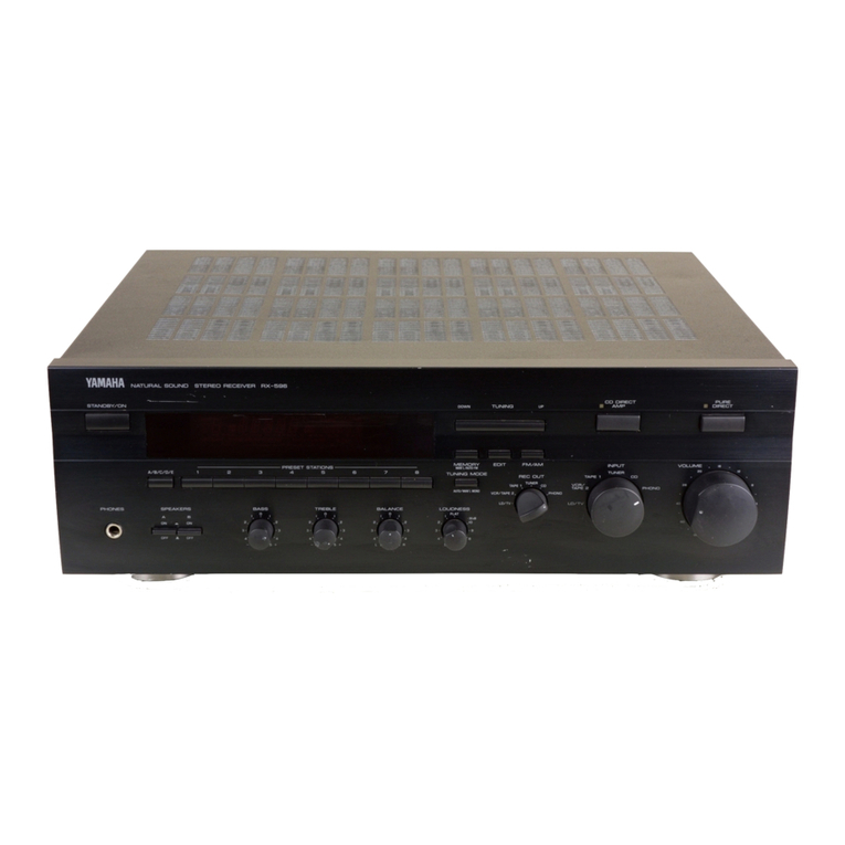
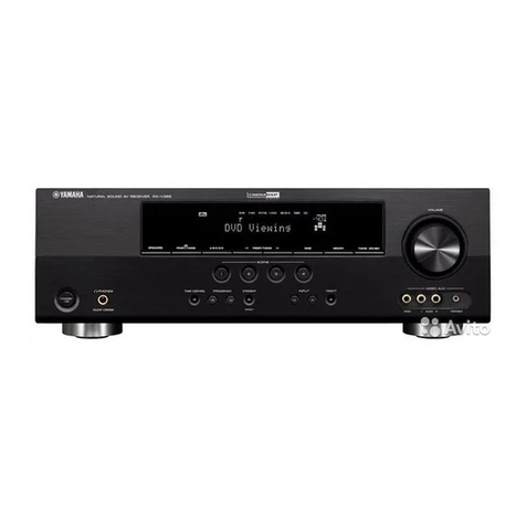
Other manuals for RX-V2600

4

Other Yamaha Stereo Receiver manuals

Yamaha RX-V4ABL User manual

Yamaha

Yamaha RX-V4ABL User manual

Yamaha Aventage RX-A870 User manual

Yamaha

Yamaha Aventage RX-A870 User manual

Yamaha MusicCast TSR-400 User manual

Yamaha

Yamaha MusicCast TSR-400 User manual

Yamaha HTR5540OM User manual

Yamaha

Yamaha HTR5540OM User manual

Yamaha AVENTAGE RX-A680 User manual

Yamaha

Yamaha AVENTAGE RX-A680 User manual

Yamaha R-700 User manual

Yamaha

Yamaha R-700 User manual

Yamaha HTR-3071 User manual

Yamaha

Yamaha HTR-3071 User manual

Yamaha CR-600 User manual

Yamaha

Yamaha CR-600 User manual

Yamaha CR1020 User manual

Yamaha

Yamaha CR1020 User manual

Yamaha RX-V559 User manual

Yamaha

Yamaha RX-V559 User manual

Yamaha R-70 User manual

Yamaha

Yamaha R-70 User manual

Yamaha CX-A5000 Instruction manual

Yamaha

Yamaha CX-A5000 Instruction manual

Yamaha R-5 User manual

Yamaha

Yamaha R-5 User manual

Yamaha RX-E100RDS User manual

Yamaha

Yamaha RX-E100RDS User manual

Yamaha RX-450 User manual

Yamaha

Yamaha RX-450 User manual

Yamaha R-8 User manual

Yamaha

Yamaha R-8 User manual

Yamaha RX-V1070 User manual

Yamaha

Yamaha RX-V1070 User manual

Yamaha RX-V383BL User manual

Yamaha

Yamaha RX-V383BL User manual

Yamaha MusicCast RX-V6A User manual

Yamaha

Yamaha MusicCast RX-V6A User manual

Yamaha RX-930 User manual

Yamaha

Yamaha RX-930 User manual

Yamaha CR-1000 User manual

Yamaha

Yamaha CR-1000 User manual

Yamaha RX-797 User manual

Yamaha

Yamaha RX-797 User manual

Yamaha MusicCast RX-V4A User manual

Yamaha

Yamaha MusicCast RX-V4A User manual

Yamaha RX-397 User manual

Yamaha

Yamaha RX-397 User manual

Popular Stereo Receiver manuals by other brands

Aiwa Z-R900 Service manual

Aiwa

Aiwa Z-R900 Service manual

Onkyo TX-NR5007 - AV Network Receiver Product release

Onkyo

Onkyo TX-NR5007 - AV Network Receiver Product release

Marantz 2238 Service manual

Marantz

Marantz 2238 Service manual

Sony STR-DN1080 Service manual

Sony

Sony STR-DN1080 Service manual

Sony ST-RV55ES operating instructions

Sony

Sony ST-RV55ES operating instructions

Kenwood KR-9600 instruction manual

Kenwood

Kenwood KR-9600 instruction manual

Sony XAV-AX6050 operating instructions

Sony

Sony XAV-AX6050 operating instructions

Pioneer SX-838 Service manual

Pioneer

Pioneer SX-838 Service manual

Pioneer AVH-2300NEX installation manual

Pioneer

Pioneer AVH-2300NEX installation manual

Denon DRA-697CI Brochure & specs

Denon

Denon DRA-697CI Brochure & specs

Harman Kardon HK 3480 owner's manual

Harman Kardon

Harman Kardon HK 3480 owner's manual

Sony CFD-V6 Service manual

Sony

Sony CFD-V6 Service manual

DaySequerra M4.2S user manual

DaySequerra

DaySequerra M4.2S user manual

Sony ICF-SW07 operating instructions

Sony

Sony ICF-SW07 operating instructions

Sony STR-DA5ES - Fm Stereo/fm-am Receiver operating instructions

Sony

Sony STR-DA5ES - Fm Stereo/fm-am Receiver operating instructions

Teac AG-H300 Service manual

Teac

Teac AG-H300 Service manual

Sony STR-DE998 - A/v Receiver Specifications

Sony

Sony STR-DE998 - A/v Receiver Specifications

Cambridge Audio Evo 150 user manual

Cambridge Audio

Cambridge Audio Evo 150 user manual

manuals.online logo
manuals.online logoBrands
  • About & Mission
  • Contact us
  • Privacy Policy
  • Terms and Conditions

Copyright 2025 Manuals.Online. All Rights Reserved.