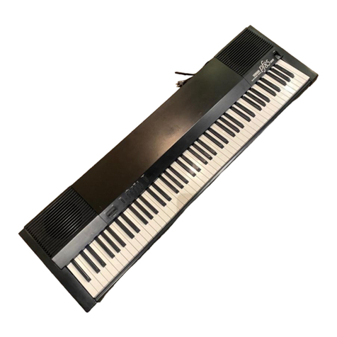
Yamaha DX1 User manual

^YAMAHA ^
DIGI1AL
PROGRAMMABLE
ALGORITHM
SYNTHESIZER
OWNER'S MANUAL

INTRODUCTION
Thank you for choosing the Yamaha DXl
Digital Programmable Algorithm Synthesizer,
The DXl is afully digital synthesizer
incorporating the state-of-the-art
tecnnology including Yamaha's superb FM tone
generator system. The DXl offers the
highest levels ot performance,
programmability and sound quality.
Please be sure to read this manual
thoroughly before you use your DXl to ensure
many hours of trouble-free use.
FEATURES
*Microcomputer-based operation offers a
tremendous range of functions in an
easy-to-use system. All functions are
selected via light-touch electronic buttons,
and data entry is carried out via buttons or
aslider control.
*Data is displayed on the LCD or LED
graphic displays, making all pertinent
parameters visioie during programming. The
LED graphic display in particular offers
simultaneous readout ot many parameters
making it easier to check overall program
status.
*64 (2 channels x32) voice memory. 256
pre-programmed voices are provided in
external ROM memory cartridges (64 of which
are the same as the voices pre-programmed in
the DXl internal memory). Voices from the
two voice channels can be used
independently, or combined as needed.
*The DXl is also equipped with a64 voice
performance memory which can store
combinations of voice and effect (modulation
wheel, foot controller, etc.) parameters ^
for easy one-touch selection. A^F
pre-programmed 64 voice ROM cartridge is
provided.
*Memory data can be stored in optional RAM
cartridges, permitting creation of an
original voice library.
*Full editing facilities permit alteration
of existing voice data.
*Totally new voices can be created using
the initialize memory function.
*The FM tone generator is arevolutionary
system which is totally programmable and
permits creating voices with anatural,
irregular harmonic structure. Two tone
generator channels—Aand B—are provided.
Each features a6-operator 32-algorithm
system. Each operator is fully programmable
permitting limitless voice creation.
*Anew 8-parameter envelope generator
system permits programming complex envelope
waveforms for unprecedented versatility. An
independent envelope generator is provided
for each operator, as well as aseparate
pitch envelope generator, ^^
*The DXl features programmable key velocit^^
sensitivity function which enables control
of volume and timbre via key pressure.
Further, the keyboard has been specially
designed to respond to the player's touch
just like ahigh quality acoustic piano.
*The keyboard scaling function enables
natural volume and timbre scaling, and
alteration of the EG response through the
keyboard range.
*The DXl provides arich variety of effects
such as pitch bend, portamento/glissando, EG
bias and LFO modulation. These can be
operated by means of four controllers: a
modulation wheel, foot controller, keyboard
after-touch response, and aunique breath
controller (optional),
*The DXl is equipped with aMIDI interface.
This permits control and transfer ot data
between the DXl and another MIDI compatible
keyboard, MIDI computer, sequencer, or other
MIDI equipment.

*Location
Avoid Placing the DXl in the following
locations:
*By windows or in direct sunlight.
*By heaters or places subject to
extremes ot heat or cold,
*Dusty places,
*P±aces subject to vibration.
*Power
*MaKe sure that your DXl is properly
adjusted to accept the AC mains
voltage and frequency in your area.
Do not under any circumstances connect
the DXl to any other type of power
source,
*Remove the AC plug from the socket
during thunderstorms.
*Connections
*Read the section in the manual on
terminals and connections carefully,
and be sure to connect the equipment
correctly,
*In order to avoid speaker damage make
sure that all power switches to
^related equipment are OFF before
^connecting.
*Operating and Transportation
*Do not apply unnecessary force to the
switcnes and knobs.
*In order to avoid broken cables and
shorts, unplug ail connection cables
from the socket whenever you move the
equipment. Always unplug connectors
by gripping the plug, not the cord.
Unplug the DXl if you are not planning
to use it for some time.
*Warranty Procedures
*Make sure you carry out the warranty
procedures at the shop where you
purchase your DXl. If the warranty
certificate is not filled out
properly, you will be required to pay
acnarge for servicing even though
your machine is still within the
warranty period,
^*Keep this manual and your warranty
Pcertificate in asafe place.
*Other Appliances
*Your DXl contains digital circuitry.
If it is used too close to radios, TVs
or related equipment interference may
result. Make sure that your DXl is
sufficiently separated from other
equipment.
CHAPTER 1DXl OUTLINE/THE FM VOICE
r-ENERATOR SYSTEM 4
1-1 DXl System Outline a
1-2 THE FM TONE GENERATOR A
CHAPTER 2DXl FEATURES AND FUNCTIONS ..6
2-1 The 4Modes of the DXl 6
2-2 Control Panel (fig. 8) 6
2-3 Connection Terminals 9
CHAPTER 3PLAY mode/PERFORJ^lANCE MEMORY. .11
3-1 PERF0PJ1ANCE MEMORY &VOICE MEMOPY H
3-2 Calling Memorv Data 12
3-3 STORE/MOVINC MEMORY 14
CHAPTER 4EDIT mode/VOICE PARAMETERS. .18
4-1 The EDIT Mode 18
4-2 The Voice Parameter Buttons
Below the LED Display 21
4-3 PERFORMANCE MEMORY/FUNCTION
SECTION VOICE PARAMETERS .... 27
CHAPTER 5FUNCTION MODE/EFFECTS AND
OTHER FUNCTIONS 31
5-1 The 3function of the
FUNCTION mode 31
5-2 The FUNCTION mode control orocess 31
5-3 PERFORMANCE MEMORY PARAMETERS. .35
5-4 MEMORY MANECEMENT A
2
5-5 MIDI INFO, CONTROL (fiq. 78) ." .* 47
CHAPTER 6STORE MODE/DATA MEMORY STOCK 52
6-1 3Varieties of the STORE Function 52
6-2 Aonlication of STORE ALL .... 53
6-3 STORE VOICE APPLICATIONS .... 54
6-4 STORE PERFORMANCE APPLICATION. .55
CHAPTER 7VOICE INITIALIZE/PROnRAMMINn
ANEW VOICE 57
7-1 Programming avoice from the
INITIALIZE MEMORY state .... 57
7-2 ENTERING VOICE PARAMETER DATA. .58
7-3 ENTERING THE PERFOR^IANCE
MEMORY PARAMETERS 59
CHAPTER 8USING THE MIDI TERMINALS ..61
8-1 ABOUT THE MIDI TERMINALS .... 61
8-2 MIDI SYSTEM CONNECTIONS
AND OPERATIONS 62
CHAPTER 9FM TONE GENERATOR THEORY ..67
9-1 Approaching the FM Tone Generator 67
9-2 FM Tone Generator Theory .... 69
CHAPTER 10 GENERAL SPECIFICATIONS ... 72
CHAPTER 11 BLOCK DIAGRAM 73

CHAPTER 1
DX1 OLTTLINEn-HE FM VOICE GENERATOR SYSTEM
1-1 DX1 System Outline
The block diagrem in figure 1roughly
outlines the DXl system. It consists of
four main sections:
(1) CONTROL PANEL
(2) FM TOIIE GmERATOR
(3) DIGITAL EG
(4) KEYBOARD
The simplicity of the systeir: nas oeen made
possible because it functions mostly on
digital principles. Based on the clock
diagram in figure 1, we'll roughly describe
each section.
(1) CONTROL PANEL
Almost all controls are logic control
switches. Other features on this remarkably
simple panel include agraphic LED display,
an alphanumeric LCD display, afew linear
controls and controller wheels.
(2) FM TONE GENERATOR
In addition to pitch, timbre and level
programming capability, these sophisticateo
tone generators are also capable of
generating noise components like those found
in natural sounds and acoustic instruments.
They offer unprecedented precision and
versatility in voice creation.
(3) DIGITAL EG
This system permits programming time-based
variations of pitch, timbre and level.
Because it is adigital system, the EG curve
can be precisely programmed in numeric form.
Further, the digital EG has 8variable
parameters permitting exceptionally
versatile EG curve generation,
(4) KEYBOARD
This is a73-key, 32-note polyphonic
keyboard with three touch functions: key
velocity sensitivity (initial touch), after
touch, and key individual after touch. This
Fig. 1. DXl Digital Synthesizer Design
-5
CONTROL PANEL
FM TONE GENERATOR
Pitch, Timbre, Level
II
DIGITAL EG
Pitch, Timbre,
Level Variation
t
:>
C^ Audio Signal
^Control
Signal
KEYBOARD
offers greatly expanded expression
capability. Further, the keyboard offers a
precision weighted-return action for the
most natural overall keyboard response.
1-2 THE FM TONE GENERATOR
The Yamaha FH tone generator permits precise
control over voice pitch, timbre and level.
The following is abrief description of Fr:
tone generator principles. See Chapter 9
for amore technical explanation of Fii tone
generator theory.
What is Fii? "
FM stands for Frequency Modulation, just as
it does when used to describe an "FM"
station or radio broaacast.
The term "modulation" means, basically, to
superimpose one signal on top of another
signal. In other words, asignal of agiven
pitch may be used to "modulate" asignal of
another pitch. The vibrato effect is an
example of alov7-f requency signal (the
vibrato) modulating ahigh-frequency signal
{the note to which vibrato is applied).
In an FH radio broadcast, a"carrier" —an
extremely high-frequency radio signal which
can be transmitted via the atmosphere—is
used to "carry" the program material. The
program material "modulates" the
radio-frequency carrier.
In the FM tone generator, the carrier and
modulator function as follows:
CARRIER: determines the level and pitch
of the sound.
MODULATOR: determines the timbre of the^
sound, "
Of course, the carrier and modulator
frequencies are much closer together in the
FM tone generator than they are in an FM
broadcast, and they are both pure sine
waves.
The 2Main Merits of FM
In an FM broadcast, since the carrier
frequency is somewhere around 80 million
hertz (cycles) and the music signal which
moaulates it contains frequencies which are
much lower—20 Hz to 20,000 Hz, the music
signal is basically unchanged by the
carrier. If we bring the frequencies of the
carrier and modulator much closer together,
however, we begin to generate new signal
components—harmonics of the modulator
and/or carrier and noise components.
It is these modulator-carrier
characteristics that we take advantage of in
the FM tone generator. Its first big
benefit is that the FH generator is capable

of closely controlling the pitch, tin.bre and
level of the sound produced without the need
for conventional VCO (Voltage Controllea
Oscillator—pitch control) ,VCF (Voltage
Controlled Filter—Timbre) or VGA (Voltage
Controlled Amplifier—level) elements.
Further, while the conventional VCF controls
timore by removing certain harmonics from
the sound, the FM tone generator works by
adding harmonics as required—and where
required—for much more sound control
versatility. In fact, the harmonic spectrum
of avoice can programmed with total
freedom.
Another rrajor oenefit of the FM system is
that noise components that conventional VCOs
are simply incapable of producing can be
easily generated. Noise is avery important
part of the sound of any acoustic
instrument—not just the instrument's pure
tonal harn.onics. For example, in aviolin
there is bowing noise, breath noise in a
saxophone sound, or the purely percussive
portion of adrum sound. The FH tone
generator system permits producing total
^pound such as these, incorporating both
surely tonal and noise spectra.
Specifically, random harmonic structures and
noise can be produceo by setting the ratio
of modulator and carrier frequencies so one
is not amultiple of the other, and by
greatly increasing the modulation level. Of
course, it is then possible to use the DXl
EG to independently control different
portions of the sound.
The FM Tone Generator and Algorithms
The DXl has two FK tone generator
channels—Aand B. Each channel has 6
OPERATORS—atotal of 12—which are the
basic FM voice building blocks. An operator
is essentially asine wave oscillator that
can be used either as amodulator or as a
carrier. Furthermore, since the DXl is an
all-digital instrument, these sine wave
oscillators function by "reaoing" the sine
wave from adigital sine wave memory, rather
^han by using conventional analog oscillator
Jpircuitry, for exceptional precision and
Stability.
The six operators in each channel can be
combineo in many ways, with different
configurations and mooulator-to-carrier
relationships. Such operator "patterns" are
called ALGCRITHilS. The simplest form of
algorithm is acombination of two
operators—one acarrier and one a
modulator. This combination is shown in
fig. 2below.
Fig. 2. FM Sound Source Basic Algorithm
Hodulatoc
Carrier
JJ
4. Modulation Signal
^Audio Signal
Vv'ithout any modulation, an operator produces
apure sine wave with absolutely no harmonic
content other than the fundamental
frequency. V/hen modulation is applied,
however, arather complex waveform with a
complex harmonic structure is produced (fig.
3). There are three main ways of
controlling the resultant waveform. They
are:
The frequency ratio between modulator and
carrier.
Modulator output level.
Feedback.
The DXl uses all three of these control
elements to create an unbelievably broaa
spectrum of natural voices.
Fig. 3. FM Waveform Variation
Waveform before modulation
by carrier. {Sine Wave) Waveform after modulation
by carrier. (Complex wave)
The actual algorithms used in the DXl are a
little more complex than the one shown
above. Carriers may be arranged "side by
side" as shown in fig. 4, or n.any
modulators may be piled on top of one
another to create a"chain" of modulation.
Figures 5—7are examples of actual DXl
algorithms, 32 different algorithm patterns
are provided, and can be used independently
in channels Aand B. The two channels can
then be mixed in any way desired to create a
range of voices unprecedented in any
electronic music synthesizer system.
Fig, 4, Parallel Carrier
Algorithm Fig. 5. DXl Algorithml Fig. 6. DXl AlgorithralS Fig. 7. DXl Algorithm30
Carrier
1
Carrier
2
Audio Signal
The two voices are
mixed and output.
iIModulator
carrier
fFeedback TT
5J,
4
I
I2 3 6
l!=rz_JL_^_JL___:=U
\^

CHAPTER 2
DX1 FEATURES AND FUNCTIONS
Despite of the fact that the DXl has avast
number of functions, its control panel is
remarkably simple. This has been made
possible by the use of many multi-function
switches that change their function
according to the number of times they are
pressed. This system of providing many
functions with the smallest number of
switches is similar to that of using an
alphanumeric keyboard for inputting commands
on alarge computer. In this section we
will briefly introduce the features and
functions of the DXl control panel.
2-1 TTie 4modes of the DX1
The DXl has four main modes. These are
selected using the MODE selectors. Each
mode has its own set of parameters,
PLAY MODE
In this mode, voice and effect data called
can be used directly in performance.
Although there is no specific switch for
this mode, it is the basic mode selected
when the three modes described below are all
turned OFF, In the play mode, the
PERFORMANCE MEMORY/FUNCTIOH and VOICE MEMORY
buttons become the play mode voice
selectors.
EDIT MODE
In this mode voice data can be programmed.
Data already contained in the voice memory
can be edited and changed, or completely new
voices can be created simply by inputting
the appropriate data. The edit mode takes
priority over the play mode,
FUNCTION MODE
In this mode the many effects used during
performance can be set. Commands related to
memory control and the MIDI terminal are
also included in this mode. This mode takes
priority over both the play and edit modes. ^
STORE MODE ^
In this mode data can be stored in the voice
and performance memories. Voice parameters
in the EDIT mode can be memorized in the
VOICE MEMORY, and function parameters and
VOICE MEMORY numbers can be combined and
recorded in the PERFORMANCE MEMORY. The
store mode takes priority over the play,
edit and function modes.
2-2 Control Panel (fig. 8)
The DX-1 control panel has the following
Fig. 8. DXl Control Panel
03^3 Sw ^M Bajqp iqmO 5Jr tS^QT ^ijjf ^^E STjjJJ itr^gj ^^" ~0
®
—
n""
n
DDDD"D'
LJ
mmvm [qm^anpaiSD ^^y^\^^^ g^x^^Sa^^^q^J(^ [^t^q/^^p [^cpqj^^jj D
o?^ *•^«* -^-^ 11
w-
^
IIII IrIrIIII

control/function groups: FUNCTION
1. MODE SELECTOR
2. VOICE MEMORY
3. CARTRIDGE SVJ
4. CARTRIDGE SLOT
5. PERFORMANCE MEMORY/FUNCTION
6. KEY ASSIGN MODE SW
7. LCD DISPLAY
8. VOICE PARAMETER SW
9. LED DISPLAY
10. DATA ENTRY
11. WHEEL CONTROLLER/ SLIDER
(1) MODE SELECTORS These selectors are used
to call the desired mode. When amode
selector is pressed its indicator lights.
*If more than one mode selector is
pressed at one time, the indicators of
all the pressed buttons will light.
However, more than one mode cannot be
selected at the same time.
*The priority of the modes is given
below.
1^ (1 STORE/2 FUNCTION/3 EDIT/4 PLAY)
EDIT/COMPARE
This button calls the edit mode. The
compare function incorporated in this
selector permits comparison of the sound of
avoice being edited with that of the
original voice. -*/»27
*The voice parameter switches arranged
beneath the LED display and the
PERFORMANCE MEMORY/FUNCTION switches
are used to select the voice parameters
to be edited, and data is entered using
the DATA ENTRY section.
*The VOICE and PERFORMANCE MEMORY
selectors are locked during the edit
mode, and cannot be changed.
This calls the function mode.
*The function is determined using the
PERFORMANCE MEMORY/FUNCTION switches
then data is entered using the DATA
ENTRY section,
*If the EDIT/COMPARE switch is either
off or flashing during the function
mode, different voice memory buttons
can be selected.
*Since the performance memory and
function mode buttons are integrated,
the performance memory cannot be
changed while in the function mode,
STORE
This is the mode which permits storage of
data in the various memory locations, ^p.S2
*The VOICE MEMORY and/or PERFORMANCE
MEMORY/FUNCTION positions are selected and
operation is performed via the DATA ENTRY
section.
*The FUNCTION switch, EDIT switch, and
VOICE MEMORY and PERFORMANCE MEMORY are
locked during the store mode, and will not
function until the store mode is disengaged.
C2) VOICE MEMORY
These are the VOICE MEMORY position
selectors. Two channels are provided, one
each for tone generators Aand B, Each
channel has 32 memory positions. The bank
selectors determine which voice bank is
selected, and the voice switches determined
which voice within that bank is selected.
*When the CARTRIDGE switch is ON the
selectors select the cartridge memory.
Positions cannot be re-selected in the
edit or store modes. ~^p.i3
H"H"HQD
BBBB
BB BBB B
®
J,„n ."ii^ ;ji,AT ••JO I'MS iMli .[ >ir^. ~V'>',"',tw'
111 1 1111I
111 1 1 1 11I
...m.., CD —EB.. ^^m^^^ „FS1.„ ..hP?^; ,__m .aa
(11 1 IT111
111 1 II1 1 1
CD <: en CD en raa CD CXI
-fi
HS
B
B'"
BB B
9B B B B
B
YAMAHA
[A]
-dh
s\
-SJ* 'snu Mm. ^I'Kr'""^!
'
.i.V-, a:y r' Sa" Piir?''"' T^^;ar'
£i^

(3) CARTRIDGE Sli? ITCHES
These switches select cartridge voices.
When pressed the VOICE MEMORY selectors
select the corresponding voices within the
cartridge,
(4) CARTRIDGE SLOTS
Cartridges are inserted here. ROM
cartridges and RAM cartridges are both
inserted into the same slots,
*vJhen VOICE ROM CARTRIDGES are inserted,
cartridge Aand Bvoices go to the
corresponding voice memory channels A
and B,
*PERFORMANCE ROM CARTRIDGES should be
plugged into the Aslot.
*Two DXl VOICE ROM CARTRIDGES, Two DX7
VOICE ROM CARTRIDGES and one
PERFORMANCE MEMORY CARTRIDGE are
provided with the DXl.
*VOICE ROM CARTRIDGES incorporate 2
banks of voices which can be selected
with aswitch in the cartridge.
Select the required bank before
inserting the cartridge in the slot,
*The DXl VOICE ROM CARTRIDGES have the
sair.e voices as the main unit on side
I, and side II contains completely
different data. The DX7 VOICE ROM
CARTRIDGES contain data not contained
in the DXl internal memory on both
banks.
*RAM CARTRIDGE features amemory protect
switch which prevents accidental
erasure of the data in the RAM
CARTRIDGE, Be sure to turn memory
protect off before attempting to write
to aRAM CARTRIDGE.
(5) perfori:amce memory/function
*In the PLAY mode, these are the
performance memory position selectors
which select amemorized voice number
and effect combination, 64 PERFORMANCE
MEMORY positions are provided. The
upper row selects the bank and the
lower row selects the memory position.
The performance name and voice name are
displayed on the LCD display, ^p,i2
*In the FUNCTIOM rr.ode these are the
function parameter selectors. The
parameter name and data are displayed
on the LCD display. -a5J
*In the EDIT mode the upper row 1—
8
buttons and lower row 1and 2buttons
become the edit parameter selectors.
The parameter names and data are
displayed on the LCD display in this
case also, ^p^
*In the STORE mode these selectors
select the performance memory to which
the store operation is targeted, ~*P.S2
(6) KEY ASSIGN MODE BUTTONS
These select which tone generator channel
will be playable via the keyboard, ^p.42
SINGLE
Only the Aor Echannel may be selected at a
time. In the polyphonic mode the maximum
number of notes that can be played
simultaneously is 32. In this case outputs
Aand Bboth output amonaural signal
corresponding to the channel in use,
DUAL
Both channels Aand Ecan be used
simultaneously. In the polyphonic mode the
maximum number of notes that can be played
simultaneously is 16.
SPLIT
This permits splitting the keyboard at any
point and having channels Aand Bapplied to
the keyboard sections above and below the
set split point. In the polyphonic mode the
maximum number of output notes is 16 for
each channel,
(7) LCD (Liquid Crystal Display)
** In the PLAY mode this display display^^
the voice name and its memory position^^
(number), or the performance memory ^^
name and its memory position,
** In the EDIT mode the parameter name
and data are displayed,
** In the FUMCTIOIJ mode the parameter
name, the control prompts and data are
displayed.
** In the STORE mode the memory position
and control prompts are displayed.
(8) VOICE PARAMETER SV7 ITCHES
When the EDIT mode is called voice data is
displayed on the LCD display and these
switches permit editing of the data.
*Pressing avoice parameter switch
selects the corresponding parameter,
and data is entered using the DATA
ENTRY section,
*Data can also be changed by
continuously pressing avoice
parameter switch. The data value
increases in 1-step increases, and ^^
when the maximum value is exceeded the^^
display begins from the lowest value
again,
(9) LED DISPLAY
This graphically displays parameter data in
the EDIT mode, Abar-graph type display
shows level information,
*In the EDIT mode, parameters and data
being worked on are shown by flashing
sections on the display.
(10) DATA ENTRY
In the EDIT, FUNCTION and STORE modes, data
entry is performed at this section.
*Data can be input either by using the
slider control or +/- button. The
slider control permits broad-range data
variation, while the +/- button permits
fine data control in 1-step increments.
The +/- switch also functions to turn
certain parameters ON or OFF,
*It also serves to answer YES or NO to
control prompts which appear on the LCD
display.
(11) WHEEL CONTKOLLER/ SLIDER
VOLUME
This is the DXi masiter volume control
BALANCE
This adjusts the volume balance between
channels Aand 3.
PORTAMENTO
This adjusts the portamento tirr.e.
*When the FUMCTION mode PORTAMENTO PEDAL
UKNOD ASSIGN is OFF, portamento will
not function. ^P.36
PITCH
This is the pitch bend wheel,
*This will not function when the
kFUNCTION moae PITCH BEaiD RANGE parameter
Pis set to 0. ^P.36
MODULATION
This controls LFO modulation. That is, the
depth of vibrato, tremolo and wow effects.
*When the FUNCTIOI] mode MOD IJHEEL ASSIGN
is set to EBC (EG BIAS CONTROL) this
functions as avolume or brilliance
control, -"p.as
*Modulation will not function when the
EDIT mode AMPLITUDE MODULATION SENS,
parameter is set to 0, and the PITCH
MODULATION SENS, parameter is set to ,^p.27
*This v/ill not function when the
FUNCTION mode MOD V7HEEL SENSITIVITY
parameter is set to or when the MOD
WHEEL ASSIGNS are all OFF, ^P.38
2-3 Connection Terminals
The following types of connection terminals
^re provided:
1. AUDIO OUTPUT
2. CONTROL CONNECTOR
3. MIDI CONNECTOR
Please connect the power cord, amplifier,
peripheral equipment and accessories
correctly, as shown in the illustration.
The connector terminals are provided in two
locations: on the rear* panel (fig, 9a), and
to the lower left of the keyboard (fig. 9b).
(1) AUDIO OUTPUT
OUTPUT (fig. 25a)
Audio outputs A, Band Pare provided. Both
unbalanced phone jack and balanced XLR type
connectors are provided for each output, for
atotal of 6audio output connectors.
This is the output for tone generator
output channel A(memory A) .However,
when the KEY ASSIGN rX)DE is set to
single, either channel Aor B,
whichever is in use, will be
simultaneously output from this jack.
This is the output for tone generator
output channel B(memory B) .However,
when the KEY ASSIGN 1X3 DE is set to
single, either channel Aor B,
whichever is in use, will be
simultaneously output from this ^ack.
P(PR0GRAr4)
This output provides amonaural rr:ix of
channels Aand B. It is normally ON,
The FUNCTION mode PROGR/iH OUTPUT ASSIGN
function can be used to independently
turn channels Aand Bon or off as
required for this output. -/>.J7
*The unbalanced phone jack outputs are
for connection to reproduction
ecjuipment with unbalanced type inputs.
In order to appreciate the extremely
broad dynamic range of the DXI we
recommend the use of ahigh-performance
keyboard amplifier or integrated PA
amplifier/speaker system.
*The balanced XLR type connectors are
intended mainly for use in professional
applications where noise must be kept
to an absolute minimum. These
teririnals should be used in sound
reinforcement and recording situations.
*The output level at outputs A, B and P
is controlled by the FUNCTION mode
OUTPUT Lt:VEL ATTENUATE parameter. If
the OUTPUT LEVEL ATTENUATE parameter is
set to 0, no sound will be output,
PHONES (fig. 9b)
This jack accepts virtually any standard
pair of headphones. It outputs amono mix
of the channel Aand Bsignals.
PHONE VOLUME (fig. 9b)
This controls the level of the headphones.
The PHONES volume control controls headphone
volume independently from the main volume
slider control.
(2) CONTROL CONNECTORS
VOLUME (fig. 9a)
This connector permits foot control of
volume level. An FC-3A foot controller can
be connected here.
*In this case the volume slider control
should be set to its maximum setting,
MODULATION (fig. 9a)
This connector perir.its foot control of the
depth of LFO modulation (vibrato, tremolo,
wow) and EG bias (volume, brilliance). An
FC-3A foot controller can be connected here.
*The foot controller will not function

if the EDIT mode AMPL. HODULATIOi; and
PITCH uODULATIOi: SHIMS. pararrieteri: are
set to 0. -P.27
*The foot controller will not functicn
if the FUIJCTIOM mode FOOT QQUT
SEIiSITIVITY parar.ieter is set to and
the FOOT CONT ASSIGiis are all OFF. ^P.38
SUSTAIN (ficj. 9a)
This perrr.its OU/CFF control of the sustain
function by connecting an FC-4 or FC-5
footswitch,
*The footswitch will not functicn if the
FUMCTIO:: ir.ooe SUSTAIIJ PEDAL ASSIGN is
off. -P.S7
PORTAIlEirro (fig. 9a)
This connector permits connection of an FC-4
or FC-5 footswitch to turn the portamento
effect OU or OFF,
*The footswitch will not functicn if the
FUI^CTION mode PORTAMEriTO TIME parameter
is set to 0, or the PEDAL ASSIGi:
parameter is turned OFF, -P.37
BREATH COtlTROLLER {fig. 9b)
ABC-1 breath controller can be connecteo
here for breath control of LFO modulation or
EG bias,
*The breath controller v;ill not function
if the EDIT mode AMPLITUDE MODULATION
and PITCH riODULATIOlI SEuS. pararaeters
are set to 0. ~*p.27
*The breath controller will not function
if the FUIJCTIOU mode BRTII C0::T.
SEMSITIVITY oarameter is set to and
the BRTII COIjT, AGSIG:;s are all OFF. -AJJ
(3) niDI CONNECTOR (fig. 9a)
MIDI stanos for Musical Instrument Digital
Interface. This interface permits
transmission and reception of digital data
for control purposes. The illEI terminal can
be connected to the YAMAHA KXl REMOTE
KEYBOARD, any other key boa re with aMIDI
terminal, or apersonal computer system. A
MIDI cable must be used, --p.si/p.72
lU
This is an input terminal which receives
data from another instrument or computer.
The KXl REMOTE KEYBOARD is also connected
here.
OUT
This is the output for the DXl digital
control signals. The DXl can be used to ^^
control other instruments, or DXl voice or ^P
performance data can be read into an
external computer.
THRU
This outputs the same data as received ct
the IM terminals, permitting chaining of
more than two instruments, computers,
sequencers or other MIDI equipment.
Fig, 9. Connection Terminals
a. Rear Panel ^oot Controller
FC-3A Footswitch
FC-4, FC-5
Audio
Regeneration Unit VOLUME MODULATION
(unbalanced
input
)
SUSTAIN PORTAMENTO
»••••*¥ 1
af
oooo YAMAHA ^S<^
PA Recording MIDI Connector
Unit
(balanced input)
Power Cable Power Switch
b. Control Panel
Phones
©M.r.. .o,uMt ^:^;:?^ ®
€^
®®
Phones Volume
Breath Controller
6C1
10

CHAPTER 3
PLAY modePERFORMANCE MEMORY
In the PLAY raode, data already in the memory
is used for performance. In this section
we'll describe how to call out the required
voice for performance, and how memory
positions can be changed without altering
the voice or performance data.
3-1 PERFORMANCE MEMORY &VOICE MEMORY
What is PERFORMANCE MEMORY?
In the DXl the two channels of internal
VOICE MEMORY or external cartridge VOICE
JIEMORY are combined with the FUNCTION raode
jHjffects to form the complete performance
~oices. The PERFORMANCE MEMORY is amemory
in which the VOICE MEMORY numbers are
combined with effects and stored. Channel
A/B corabinations and the addition of effects
can be freely set up and stored in the
PERFORMANCE MEMORY. In the PLAY mode
complete voices can be easily selected using
the PERFORMANCE MEMORY switches. ^P.12
*When the DXl is initially shipped, its
PERFORMANCE MEMORY contains 64
combinations pre-programmed at the
Yamaha factory, permitting immediate
performance when the instrument is
received. The PERFORf-J^ICE MEMORY
banks 1—4hold the internal voice
memory, and banks 5—8select the DXl
VOICE ROM cartridge side II memory.
*Voice and effect combinations are
stored in the PERFORMANCE MEMORY as a
number. The actual voice data {the
EDIT mode parameters) are not
memorized.
•* The internal RAM (Random Access Memory)
VOICE MEMORY can be used to store all
EDIT raode parameters. When the
instrument is initially shipped, the
VOICE MEMORY contains 32 voices in
each channel, Aand B, for atotal of
64 voices.
*The 5ROM (Read Only Memory) cartridges
provided contain original Yamaha
voices and effect data.
*The two DXl VOICE ROM CARTRIDGES each
contain 64 voices for atotal of 128
voices. Each cartridge has two sides:
Iand II. The I/II switch is used to
select the desired side. Side I
contains the same voices as are
initially stored in the instrument's
internal memory, and side II contains
different voices. Be sure to switch
to the desired side before plugging a
cartridge into the DXl. ^p.13
*The two DX7 VOICE ROM CARTRIDGES
provided also contain 64 voices each
for atotal of 128 voices.
*The PERFORI'IANCE ROM CARTRIDGE contains
the same 64 effect "settings" as the
DXl internal PERFORMANCE MEMORY. When
this cartridge is inserted into the
pxl, the data it contains is called
into the internal memory, combined
with the desired voice data and used
rCor performance.
Up to 32 original voices {voice
parameters) or 64 original effects
(function parameters) can be stored in
the RAM cartridges. When aRAH
cartridge is plugged into the DXl,
original data can be freely called
from it.
The RAM cartridges are initially
shipped set up with the VOICE MEMORY
(voice parameter) format. To use the
RAM cartridge for PERFORMANCE MEMORY
storage (function parameters), use the
FUNCTION mode CHANGE CART, FORMAT -*P.46
function.
The BUFFER
The buffer is aspecial separate memory
into which DXl data is called from
memory for performance or editing, A
buffer is provided for the PERFORMANCE
MEMORY and the VOICE MEMORY. When a
memory number is selected, the data
corresponding to that memory number is
read into the buffer (fig. 10),
In the PLAY mode data read into the
VOICE EDIT BUFFER and PERFORMANCE EDIT
BUFFER is used as is for performance.
In the EDIT mode VOICE MEMORY data is
read into the VOICE EDIT BUFFER for
editing.
Fig, 10. Buffer Circuitry
VOI(X MEMORY
Calling
BANK 1-4 X
VOICE 1-8
X2ch sent
to memory.
EDIT
BUFFER
FUNCTION
BUFFER
PERP0RI1AN(X
lenoRV
Calling
TTT
T
DANK 1-e X
VOICE 1-8
sent to
memocy.
Store XData Alteration
Performance
IVPiCe M(MO«r 1
BANK ¥OIC(
Ca-
Select Ach BANK
1-VOICE 1
Salect-
BAMK 1
VOICE CrfliPisPosE
11

*In the FUNCTION mode PERFORMANCE MEMORY
effect data is read into the
PERFORMANCE EDIT BUFFER for editing.
*In the STORE mode, data in the VOICE
EDIT BUFFER or PERFORMANCE EDIT BUFFER
is stored or copied into the VOICE
MEMORY or PERFORMANCE MEMORY.
*In the DXl the memory backup system
also provides backup power to the
buffer data. When the DXl power is
turned OFF, the basic data which was
being used at the time is held in
memory, and is available immediately
power is turned back on.
3-2 Calling Memory Data
(1) Calling the DXl PERFORMANCE MEMORY (fig,
11)
With the PERFORMAlN'CE MEMORY it is possible
to call out voice data and effect data
simultaneously. At the same time the effect
data is called into the PERFORMANCE EDIT
BUFFER, the selected voice number data is
called into the VOICE EDIT BUFFER.
(a) Turn all MODE selectors (EDIT,
FUNCTION, STORE) OFF.
*It does not matter if the EDIT switch
is flashing at this time.
(b) Insert two VOICE MEMORY CARTRIDGES
into the DXl,
(c) Using the upper row of 8bank
selectors in the PERFORMANCE
MEMORY/FUNCTION section, select the
desired bank number, and select the
desired voice +effect with the lower
row of 8buttons.. In this way atotal
sound, incorporating the voice data
and effects, is called,
*As shipped, banks 1—4contain the
internal DXl VOICE MEMORY, and banks
5—8contain the cartridge voice data.
(d) The LCD display displays the
performance name as "PERFORMANCE
MEMORY #1-1 **XXXX**'', or the voice
name as "INT Al-1 YYYY POLY SRC=0 INT
Bl-1 2ZZZ POLY SRC=0'',
*The "ftl-l" in the performance name
display is the memory number, and XXXX
is the performance name (fig. 12),
*In the voice name display the upper and
lower rows display the channel Aand B
voice names, respectively, "INT Al-1"
and "INT Bl-1" are the memory numbers,
while "YYYY" and "ZZZZ" are the voice
names. The data following "POLY" are
Fig, 11. Calling Internal Performance Memory
function parameters that need to be
checked for performance (fig, 13) .-/>.35
*The voice name and performance name
display can be switched by pressing
the bank selectors.
*When the KEY ASSIGN MODE is set to
SINGLE, the voice name displayed is
either that of channel Aor B
depending on which is in use.
*If a PERFORMANCE MEMORY CARTRIDGE (i.e.
acartridge formatted for PERFORMANCE
MEMORY) is inserted in the DXl,
selecting banks 5—8results in a
momentary "**ERROR** Cartridge format
conflicti" message, and the voice
data will be called from the internal
VOICE MEMORY, banks 1—4, In this
case go back to step (b) above and
repeat the process correctly.
Fig. 12. Method of Indicating Performance Name
Memory Number
FEF: FCi F: MHi\ CE M EnQRV Ittl-ll
+:+: :f: I':.-i V. ^V
!
=^
Performance Name
Fig. 13, Method ot Indicating Voice Name
Memory
Number Voice Name Function Data
±=-. ,... 1it
II HT. PI -II jVVVVirPQLV SRC =E1|
INT. Bi-1 ZZZZ POLV SRC=Q
(2) Calling the internal VOICE MEMORY (fia.
14)
In the PLAY mode it is possible to use the
DXl VOICE MEMORY switches to directly call
VOICE MEMORY data into the VOICE EDIT BUFFER
without calling aPERFORMANCE MEMORY (in
which the voice number is combined with
effect data) and add effects as required
while playing.
(a) Turn all MODE selectors OFF.
(b) Use the bank select switches in the
VOICE MEMORY switch group to select
the desired banks for channels Aand
B.
*If the KEY ASSIGN MODE is set to SINGLI
then only channel Aor channel B,
whichever is in use, needs to be set,
(c) Then, using the VOICE MEMORY voice
switches, select the desired voice
number. This causes the selected
VOICE MEMORY data to be called into
the VOICE EDIT BUFFER,
O m
(c)
F-EPFCtRMHUCE MElnuRV III- 1+^t
)
VpinF(M„</vMa MfMr>H, (.,^f.tl!)^ '
;!::
""* '""" 1*1^' '"J" pp^^r. Avr,
11111—
m,^ dD en on .™, ,FP-^ cn OD
(d) Displays change in voice f
and performance names
when lighted bank switch i(b)Place cartridges!
is pressed. |in cartridge |
slot.
n~i CD CXI gj CEJ CD CQ CD
(c)Select desired bank,
performance, and voice
switch.
LBS
_L
(a)Mode selectors
(edit, function, store)
all off,
12
Select side
cartridge ot
to be used
-(when using
ROM cartridge)
.

*The selected PERFORMANCE MEMORY data
will be effective with the voice data
called until the FUNCTION mode is used
to reset the perforance memory data,
(d) The voice name display consists of
the name o£ the voice called. The
"INT" portion of the display indicates
that the internal memory is selected.
*The performance name will not change
even if the VOICE MEr40RY buttons are
pressed,
(3) Calling acartridge VOICE MEMORY
It is also possible to use the DXl VOICE
MEMORY switches to directly call VOICE
MEMORY CARTRIDGE data into the VOICE EDIT
BUFFER for performance. In particular this
process is suited for calling voice data
from the DX7 VOICE ROM CARTRIDGES.
(a) Turn all MODE selectors OFF.
(b) In the case of aROM cartridge set
the cartrdge bank selector switch
before inserting the cartridge.
(c) Insert the cartridge into the
Ik cartridge slot.
W(d) Press the CARTRIDGE switch to
initialize the cartridge access mode.
*If the CARTRIDGE switch is pressed
without inserting acartridge the LCD
display will show ***ERROR** Cartridge
not ready!". In this case go back to
step (c) and properly insert the
cartridge,
*If aPERFORI-iANCE MEMORY CARTRIDGE (a
cartridge formatted for PERFORMANCE
MEMORY) is inserted, the ''**ERROR**
Cartridge format conflict!" message
will be displayed. In this case the
data originally in the buffer will not
be affected. Go back to step (c) and
insert the correct cartridge.
(e) Using the VOICE MEMORY BANK switches
select the desired bank.
*If the KEY ASSIGN MODE switch is set to
SINGLE, then only channel Aor B,
whichever is in use, needs to be set.
(f) Using the VOICE MEMORY voice switches
select the desired voice number. This
causes the selected cartridge voice
number to be called into the VOICE
EDIT BUFFER ready for performance.
*The effects are set up according to the
currently selected PERFORMANCE MEMORY
unless the FUNCTION mode is used to
reset the PERFORMANCE MEMORY
parameters.
(g) The voice name display displays the
name of the voice called from the
catridge,
*The "EXT" portion of the display
indicates that the external cartridge
memory is being used.
(4) Calling acartridge PERFORMANCE MEMORY
(fig. 16)
It is possible to call PERFORMANCE MEMORY
CARTRIDGE data into the PERFORMANCE EDIT
BUFFER and call internal VOICE MEMORY data
into the VOICE EDIT BUFFER, combining the
two for performance,
*The method for calling data from the
PERFORMANCE MEMORY CARTRIDGE is
different from that for calling data
from aVOICE MEMORY CARTRIDGE, so care
should be taken to follow the correct
procedure,
(a) Turn all MODE selectors (EDIT,
FUNCTION, STORE) OFF.
Fig. 14. Calling Main Unit Voice Memory
(b)Specify bank
s
m
number.
t
(b)
(c) Specify voice number,
t'^"
t
(c)
PERFORMPlHCE MEMORV Jl 1-1
(ci)Displays change in voice and
performance names when lighted bank
switch is pressed.
BBB
I \ I
(a)Hode selectors all off.
Fig, 15. Calling Cartridge Voice Memory
(e)Specify. memory (f)Specify voice
bank. number.
EXT. fli-1 WW POLV SRC =8
EXT. ei-1 ZZ2Z POLV SRC-e
(ff) Voice name display.
t
(e)
1
1BANH
Ilia
®1111
13't 4
11 11
1VOICE
133Ji678
1111 1 1
;?3J667B
II
t
(f)
COWPflHt HJHCII.
mm
tf-jlnsert f
^'cartridges, |
.„.., .^.^.,. CiBTRIDGE B
STOHt CiBTRIDGE B
(b)Select
side ot
cartridge
to be used
,^_(when using
ROM
cartridge)
•
(a)Mode selectors all off.
Md)Press cartridge
switches.
13

(b) Insert the PERFORMAMCE MEMORY
CARTRIDGE into cartridge slot A.
*The cartridge Bslot cannot be used.
*If the PERFORMANCE MEMORY CARTRIDGE is
inserted into the Bslot, the
"**ERROR** Cartridge not ready!"
message v/ill be displayed, when the
following operations are performed.
(c) Press aiRTRIDGE switch Awhile
holding down any one of the
PERFORMAMCE MEMORY/FUHCTIOM section
buttons. This initiates acces to the
PERFORMAMCE MEMORY CARTRIDGE,
*When the PERFORMANCE MEMORY CARTRIDGE
has been accessed, the last section of
the upper row of the performance name
display will read '•<<CARTRIDGE»''
.
*If a PERFORMANCE MEMORY switch is not
held, or it is released before the
CARTRIDGE button is pressed, or a
VOICE MEMORY CARTRIDGE is inserted
instead of aPERFORMANCE MEMORY
CARTRIDGE, the '•**ERRROR** Cartridge
format conflictl" message will be
displayed, and the desired data will
not be read.
(d) Then by using the PERFORMA^iCE MEMORY
bank and PERFORMANCE &VOICE switches,
the desired effect data can be called
into the PERFORMANCE EDIT BUFFER.
*Only cartridge data which is called
into the PERFORMANCE EDIT BUFFER can
be used. Once the cartridge is
removed from the cartridge slot, all
other PERFORMANCE MEMORY positions
other than the one that was called
into the PERFORMAl^JCE EDIT BUFFER can
no longer be used. Further, if the
CARTRIDGE switch is turned OFF then
the internal PERFORMANCE MEMORY will
be called into the PERFORMANCE EDIT
BUFFER and the cartridge data will be
lost.
*If the effect data in the PERFORMANCE
EDIT BUFFER needs to be saved, use the
store performance function, -^p.S3
*In order to use all the PERFORMANCE
MEMORY CARTRIDGE data in the internal
memory, use the load function, ~*p.46
*Since the PERFORf-lANCE ROM CARTRIDGE
supplied with the unit contains the
same data as the internal PERFORMANCE
MEMORY at the time of shipping, only
banks 1—4can be used, VOICE MEMORY
CARTRIDGE data is set for banks 5—8,
however, since aVOICE MEMORY
CARTRIDGE cannot be inserted, the
internal VOICE MEMORY data is
automatically used,
(e) The performance name and voice name
are displayed on the LCD display each
time the bank switches are pressed.
The performance name display is
"PERFORIiANCE MEMORY #1-1 <<CARTRIDGE>>
**XXXX**".
*When the supplied PERFORMANCE MEMORY
ROM cartridge is used and one of the
banks 5—8is selected, "Cartridge
format conflict!" will be displayed
momentarily before the performance
name. As for the voice name, the
lower display row will read •'**ERROR**
Cartridge not ready 1". This indicates
that banks 5—8are set up to use the
VOICE MEMORY CARTRIDGE data.
*When it is necessary to change the
internal VOICE MEMORY data use the
VOICE MEMORY and bank switches to
select the desired voice data.
*Internal PERFORMANCE MEMORY data cannot
be called during PERFORMANCE MEMORY
CARTRIDGE access. The cartridge M
switch must be turned OFF in order to"
call the internal PERFORMANCE MEMORY.
*If the PERFORMANCE MEMORY CARTRIDGE is
removed while it is being accessed,
and the internal PERFORMANCE MEMORY is
selected, an error will result and
data may be lost.
3-3 STORE/MOVING MEMORY
The DXl permits changing the positions of
the PERFORMANCE MEMORY and VOICE MEMORY,
The combined preset voices in channels Aand
Bcan be selected and re-stored in the
PERFORMANCE MEMORY as required.
*The memory protect function is
automatically turned on when the DXl
power is turned on in order to prevent
accidental erasure of the internal
memory. The memory protect function
must be turned OFF in order to change
locations of either the PERFORMAiJCE or^
VOICE MEMORY. i
*When PERFORMANCE or VOICE MEMORY is
moved to anew position, the data that
was originally in that position is
erased. The position from which the
data has been moved, however, still
contains the original data. To
Fig, 16. Calling Cartridge Performance Memory
... ,PERFORtlRHCE (lEMORV a1-1< <CFtRTP IDGE> >
(A) II*** WW *+
\- P(HFORM*NC£
WAVt SPEtn DtLA PMD CMS MP KfV SVNC KfV SVNC
ryp nn CO mrr; m
TFtANSPOSl VOICt HAMt
^
(d) Specify bank number and
voice number.
(c)Press cartridge switch A
while holding downj^upper/
lower level performance
memory/function switch.
I
CAftTRIDGE A
B B "
I I
r
(a)Mode selectors all off,
14
m
(b)
Insert performance
memory cartridge
in cartridge
slot A.

prevent the loss of voice data, be
sure to save important voices in an
external RAM cartridge. ^p.4S
(1) Moving Internal PERFORMANCE MEMORY Data
(Fig. 17)
(a) In order to turn OFF the memory
protect function, press the FUNCTION
switch to enter the FUNCTION mode.
(b) Press button 6in the lower row of
the PERFORMANCE MEMORY/FUNCTION group,
using the memory management function
to call the PROTECT MEMORY WRITE
function.
(c) The LCD display will show "Internal
memory write protect ON". Press the
DATA ENTRY section NO switch, and the
display will read "Internal memory
write protect OFF", indicating that
the write protect function has been
turned OFF. Then exit the FUNCTION
mode and return to the PLAY mode.
(d) Select the PERFORMANCE MEMORY
.position to which you wish to move the
}data.
(e) Select the desired A/B channel VOICE
MEMORY combination.
(f) Use the STORE switch to switch to the
STORE mode. When this is done, the
"STORE ALL FROM >> CURRENT EDITING TO
»CURRENT SELECTED" message will be
displayed.
*The STORE ALL mode permits simultaneous
writing to all the internal
PERFORMANCE MEMORY and VOICE MEMORY
positions, ^p.53
(g) Press the DATA ENTRY section YES
switch to begin the store operation.
The data combination selected is
automatically stored in the
PERFORMANCE MEMORY.
*If the memory protect function has not
been turned off prior to the above
operations, the "**ERROR**
W-protected" message will be
displayed, and store will not be
possible. In this case go back to
step (a).
(2) Moving VOICE MEMORY Data {fig. 18)
(a) Switch to the FUNCTION mode in order
to turn off the memory protect
function.
(b) Call the PROTECT MEMORY WRITE
function.
(c) After pressing the DATA ENTRY section
NO button, return to the PLAY mode.
(d) In order to move voices between the
internal memory and acartridge
memory, or to change voice positions
within acartridge, make sure the
appropriate cartridge is inserted in
the cartridge slot.
*To move voices from the cartridge to
the internal memory (single load)
press the CARTRIDGE switch.
*To move voices from the internal memory
to aRAH cartridge {single save) make
sure the cartridge memory protect
switch is OFF, that the cartridge is
properly inserted, and that the
CARTRIDGE switch is not pressed.
*To change the position of voices within
aRA!1 cartridge, make sure the
cartridge memory protect switch is
OFF, the cartridge is properly
inserted and the CARTRIDGE switch is
pressed.
*It is not possible to store within a
ROM cartridge.
*ARAM cartridge formatted for VOICE
MEMORY (=00) must be used to store
Fig. 17. Shifting and Combining Internal Performance Memory Data
(f) STORE
ALL FROM>>CURRENT EDITING
TO>>CURRENT SELECTED
QO NO T£S
1
1
<c) (g)
(e)Specify A/B channel combinations.
OiCf
m
m
^
^
(e»
voice MEMORr -
J1VOICE
1jL 1'1'1 , '1•1'.•,
111 1
1
H1JSLMM
':3*b67s
111 1 1 1 1
(e)
PtRfOHMANCf MEMORV/ (UNCTION
WAVt SPECD DELi ''USCILLATOn
PMC PM3 BMO MY 5TMC t.V< STMC
mrwi mpti nn mmm
TRANSPOSE VOICt N*M[
-''"°"°'" IIII I I I I^
mCT? mfTi i~yi i;;n i~n r*yi 3
CXI CXI CX]
{d)SeIect memory position.
(b)
Q B Q
t t
(a)(c) (f)
15

voice data. Acartridge formatted for
performance data (=01) cannot be used.
(e) Using the VOICE MEMORY switches
select the voice that you wish to
change the position of.
(f) Switch to the STORE mode, and in
answer to the LCD display prompt,
press the DATA ENTRY section NO
button.
(g) The display will read "STORE VOICE
FROM »INT Al-1 XXXX TO »INT Al-1
XXXX", indicating that VOICE MEMORY
position change is now possible.
*The store voice function works only to
store VOICE MEMORY data. ^P.53
*0n the display, the "INT Al-l" is VOICE
MEMORY position and "XXXX" is the
voice name.
*Using the STORE VOICE function it is
possible to store voices in only one
channel at atime. In order to change
positions in both channels Aand B, go
back to step (d) after storing one
channel and repeat the procedure for
the other channel,
(h) After using the VOICE MEMORY bank and
voice switches to set the position to
which you wish to move avoice, the
data following the "TO" portion of the
display will show the selected
position.
*To move data from acartridge to the
internal memory {single load) turn off
cartridge access using the CARTRIDGE
switch before selecting the position
in the internal memory to which the
data is to be moved.
*To move data from the internal memory
to aRAM cartridge (single save) turn
on cartridge access using the
CARTRIDGE switch before selecting the
position in the cartridge to which the
data is to be moved.
*If aPERFORMANCE MEMORY CARTRIDGE is
inserted, the "**ERROR** Cartridge
format conflict!" message will be
displayed after the CARTRIDGE switch
is pressed,
(i) Press the data entry YES key to begin
the actual store operation. This
completes the voice move process.
(3) MOVING PERFORMANCE MEMORY (fig. 19)
(a) Enter the FUNCTION mode in order to
turn off the memory protect function.
(b) Call the PROTECT MEMORY V7RITE
function,
(c) Press the DATA ENTRY NO key then
return to the PLAY mode.
(d) To move data between the internal
memory and cartridge memory, or within
acartridge, insert the appropriate
PERFORMANCE MEMORY CARTRIDGE into
cartridge slot A.
*In order to move data from acartridge
into the internal memory (single load)
press CARTRIDGE switch Awhile holding
down the appropriate PERFORMANCE
MEMORY/FUNCTION switch. This
initiates cartridge access. If the ^
PERFORMANCE MEMORY/FUNCTION switch is^
not pressed or it is released before
the CARTRIDGE switch is pressed, the
DXl expects aVOICE MEMORY CARTRIDGE
operation and an error results. In
this case the LCD display will read
"**ERROR** Cartridge format
conflictl".
*To move data from the internal memory
to an external RAM cartridge (single
save) turn the catridge memory protect
switch OFF, insert the cartridge into
its slot, and make sure the CARTRIDGE
switch is off.
*To move data within aRAM cartridge,
turn the cartridge memory protect
switch OFF, insert the cartridge, then
press CARTRIDGE switch Awhile holding
the appropriate PERFORMANCE
MEMORY/FUNCTION switch to initiate
cartridge access. If the PERFORMANCE
Fig. 18. Moving the Voice Memory
(«)
.' Ci ICEFPCiMi VINT. fll-1
to::: >INT. Fll-1
(e) Specify voice of position
to be cnanged. ^j^j (e)
_(c) (i)
I\\
NO VfS
1 I I
IIIVOICE Ml
4
—
'-^—h-i-
m
(9
^
^E
ttf
(e) (h) (e)
m[£)
(d)Insert a
cartridges*!
(h)
(h)
-(f)-
16
(e)

MEMORY/FUNCTION switch is not pressed,
or it is released before the CARTRIDGE
switch is pressed, the DXl expects a
VOICE MEMORY CARTRIDGE access
operation, resultig in an error. In
this case the LCD display will read
"**ERROR** Cartridge format
conflict!",
*If the cartridge is inserted into
cartridge slot B, the LCD diplay will
read "**error** Cartridge not ready!".
*The ''**ERROR*** Cartridge format
conflict 1" message will also appear
if acartridge which has been
formatted for VOICE MEMORY (=00) is
inserted instead of one formatted for
PERFORriAMCE MEMORY,
(e) Use the PERFORMANCE MEMORY/FUNCTION
switches to select the voice you wish
to move,
(f) Switch to the STORE mode.
(g) Press DATA ENTRY NO button twice,
(h) The display will now read "STORE
PERFORMANCE FROM >> CURRENT XXXX TO »
INT Pl-1 XXXX", indicating that it is
now possible to change PERFORMANCE
MEMORY position.
*The STORE PERFORMANCE function can only
be used to store PERFORMANCE (/[EMORY
data. -*p.S3
*The "INT Pl-1" portion of the display
indicates the PERFORMANCE MEMORY
position, and "XXXX" is the
performance name,
(i) Using the PERFORMANCE MEMORY/FUNCTION
switches, select the position to which
you wish to move the data. The
selected position will be displayed on
the LCD display following the "TO"
portion.
*To move data from acartridge to the
internal memory (single load) turn off
cartridge access using the CARTRIDGE
switch and select the position to
which you wish to move the data.
*To move data from the internal memory
to an external RAM cartridge press the
CARTRIDGE switch to enable access from
the internal memory to the cartridge,
and select the position to which you
wish to move the data.
*When attempting to move internal data
to aRAM cartridge, if acartridge
formtted for VOICE MEMORY (=00) is
inserted instead of one formatted for
PERFORMANCE MEMORY (=01) the
"**ERROR** Cartridge format conflict!"
message will be displayed when the
CARTRIDGE switch is pressed. Be sure
to use acartridge which has been
formated for PERFORMANCE MEMORY
(format =01) using the FUNCTION mode
CHANGE CART. FORMAT function, -P-«
(j) Press the DATA ENTRY section YES
button to begin the store operation.
This completes the memory move
process.
*If the memory protect function is not
turned off prior to the above
operations, the "**ERROR**
W-protectedl" message will be
displayed. In this case go back to
step (a) and repeat the procedure.
*VJhen moving internal data to a
cartridge, or when moving data within
acartridge, be sure to turn the
cartridge memory protect switch back
ON after the operation.
Fig. 19. Moving Performance Memory
(h)
STORE FROM>> CURRENT KXX
PERFORMflNCE T0>>[NT.P1-1 XXM
m
(e)Specify voice ot position
to be Changed, (DSpecify position
Ito be moved to.
PtWFORMAMCF MtMOnv fUMCTIOM
I
(c) U)
no Y£S
PMS AMD HFT STWC Uy SYHC
^1=PT
IHANSPOSE VOICr NAM —9?»,« CI3 ^^^^^inBd^L- C23 CD
PiFlFOFMANCE
t. -tOKli 13 CO C23 d] PD OD C33 ^D
t(d)Insert performance
memory cartridge in
cartridge slot A.
on CXI i=d
(cr)p]:ess NO twice in
succession. (e) (i)
(b)
tt
(a}(c) (f)
17

CHAPTER 4
EDIT mcxte/VOICE PARAMETERS
In the EDIT mode, the VOICE MEMORY voice
parameter data can be read into the VOICE
EDIT BUFFER and edited. The vast number of
parameters that can be edited permits
extremely broad-ranging voice creation.
After editing, the new data can be re-stored
in the VOICE MEMORY,
4-1 The EDIT mode
(1) The EDIT process
In the EDIT mode, the many voice parameters
in the VOICE MEMORY are read into abuffer
and edited. Since the DXl PERFORMANCE MEMORY
settings are apart of the voice created, the
PERFORMANCE MEMORY will also be involved in
the editing process. The following two
variations on the editing process are
possible:
(I) The VOICE MEMORY for aspecific voice
is altered without changing the PERFORMANCE
MEMORY.
(II) Both the edited VOICE MEMORY and
PERFORMAl^CE MEMORY are re- stored as anew
voice.
*I:
Editing the VOICE MEMORY without changing
the PERFORMANCE MEMORY.
EDIT target selection =PERFORMANCE MEMORY
selection =^
Switch to EDIT mode =^
Set data =^
Store EDIT data =replace VOICE MEMORY,
*II:
Re-storing both the edited VOICE MEMORY
and the PERFORMANCE MEMORY as anew
voice.
EDIT target selection =VOICE MEMORY
selection =>
Switch to EDIT mode =:>
Set data ^
Store EDIT data =Set new VOICE MEMORY and
PERFORMANCE MEMORY.
(2) EDIT mode selection/Loading the buffer
*I: PERFORMANCE MEMORY selection
(fig. 20)
This is for the case in which the VOICE
MEMORY data is edited and re-stored while the
PERF0Rf4ANCE MEMORY is left unchanged.
(a) Turn all mode selectors (EDIT,
FUNCTION, STORE) OFF.
*It does not matter if the EDIT switch is
flashing,
*To edit RAM CARTRIDGE VOICES, first turn
the cartridge memory protect OFF, then
insert the cartridge into the cartridge
slot.
*After editing data from aROM cartridge,
the new voice can not be written back
into the same cartridge,
(b) Select the PERFORMANCE MEMORY position
to be edited.
*The PERFORMANCE MEMORY can not be
re-selected once the EDIT mode is
entered.
*II; VOICE MEMORY selection (fig. 21)
This is for the case in which both the
edited VOICE MEMORY and PERFORMANCE MEMORY
are re-stored as anew voice.
(a) Turn all mode selectors (EDIT, A
FUNCTION, STORE) OFF,
*It does not matter if the EDIT switch is
flashing.
*To edit ROM cartridge voice data, first
set the switch on the cartridge to the
appropriate bank, insert the cartridge
in the cartridge slot and press the
CARTRIDGE switch.
*To edit RAM cartridge voice data and
store the results in the same
cartridge, first turn the cartridge
MEMORY PROTECT switch OFF, insert the
cartridge into the cartridge slot, then
press the CARTRIDGE switch,
*To edit RAM cartridge voice data and
store the results in the internal
memory, insert the cartridge into the
cartridge slot with the MEMORY PROTECT
switch ON, then press the CARTRIDGE
switch.
*If aPERFORMANCE MEMORY CARTRIDGE is
inserted, the error message "**ERROR**
Cartridge format conflict" will be ^^
displayed when the CARTRIDGE switch id9
pressed,
(b) Select the VOICE MEMORY to be edited,
*The selected VOICE MEMORY can not be
changed once the EDIT mode has been
entered.
Fig. 20. Selecting Performance Memory
coMPam ^u^lCIlO^ 5I0M[
BB B
(a)Hode selectors
all off.
(b) Select
position
to be
edited. c. B'
Fig, 21. Selecting Voice Memory
^B-- B'
ICTlON STORE
p=] f===] F==l (b)Select
1__J I_J I1yoj,;^
(a)Mode selectors
all off.
to be
edited. "B-
L_
18

(3) Sv/itchintj to the EDIT mode and Entering
Data (Fig, 22)
{c) Enter the EDIT mode using the
EDIT/COMPARE switch. This makes it
possible to alter the data in the EDIT
BUFFER.
(d) The VOICE MEMORY channel will
automatically be selected/ and the
target EDIT voice indicator will flash.
*If the KEY ASSIGN MODE switch is set to
DU/iLr sound will be output from both
channels Aand B, In order to monitor
only the target EDIT voice, set the
BALANCE slide control all the way to
the corresponding channel.
(e) The LED and LCD displays display the
data for the target voice,
*The leftmost operator select switch
determines which individual operator
data is displayed.
*The LED display displays the data for
the parameter shown belov7 it.
*The LCD display shows the data of
.parameter selected by the PERFORMANCE
fMEMORY/FUNCTION switch.
(f) Select the parameter to be edited
using the row of voice parameter
switches below the LED display, or the
PERFORI-iAlXE liEnORY/FUNCTION switches.
*The voice parameter switches include
most of the FK tone generator and
operator functions that are essential
for voice creation. -*p.27
*The PERFORM/J^ICE MEMORY/FUNCTION switches
include LFO modulation-related effects
that affect all operators
simultaneoulsy. ~*p.27
*Envelope generator voice parameter Rl is
automatically selected. Simply press
the appropriate switch to select
another parameter,
(g) Set the desired data value using the
DATA ENTRY section.
*Data can also be set by continuously
pressing the selected (flashing)
PARAMETER switch.
*Use the COMPARE switch to compare the
sound of the edited data v;ith the sound
of the original data. -»a^
(h) To set the parameters for each
operator, use the OPERATOR SELECT
switches to select the operator to be
worked on. ^p.21
*Using the OPERATOR ON/OFF switches it is
possible to concentrate on asingle
operator, permitting extremely fine
sound control, -^p.22
(i) After editing on one channel has been
completed, switch over to the other
channel and perform any necessary
editing on that channel. Either
channel can be selected by pressing a
bank or voice switch of the channel you
wish to select.
*Also set the balance slider all the way
to the appropriate channel.
(4) Storing Edit Data
In order to store edit data, astore
operation must be performed. Two processes
are possible: (1) Storing data without
changing the memory position, and (II),
storing data in anew VOICE MEMORY or
PERFORMANCE MEMORY position.
*Each time power to the DXl is turned on,
the internal memory protect system is
activated in order to prevent
accidental memory erasure. This
function must be turned off in order to
perform astore operation.
*VJhen astore operation is performed,
data originally in the memory to which
the store is performed will be erased.
Data which needs to be saved should
therefore be stored in an external RAM
cartridge, -/»4ff
*In order to store edit data on an
external cartridge, acartridge
formatted for VOICE MEMORY storage must
be used. Acatridge formtted for
PERFORMANCE MEMORY cannot be used.
JFig, 22. Switching to Edit Mode and Entering Data (e)LED display
1
SEtECI 1
11
L(h)Operator select.
HH
:a9SM99W9gm 0\
MnSl JM
(g)
n
Set balance slider to full
to monitor the individual
voice in dual mode.
Sa-B-
(d)Voice selected for
editing flashes.
(i)Edit another channel
voice by pressing the voice or
bank switch to change channel.
Parameter switch
BBB B ^
BBBBB SbB
t
(CJ
EL) IT nODE :::Lru:::::
19

*I: Replacing an Original VOICE MEMORY
(fig. 23)
In order to re-store edited data in tVie
original memory locationr use the STORE ALL
function (the VOICE MEMORY and PERFORMAi-TCE
MEMORY are simultaneoulsy re-stored in their
original locations),
*Using the STORE ALL function it is
not possible to move data to another
memory location, move data from one
channel to another, or move data from
the internal memory to an external
cartridge.
*The STORE ALL function makes it possible
to store internal VOICE MEMORY data
back into the same internal memory
location, or to store cartridge memory
data back into the same cartridge
memory location. ^P.53
(j) In order to defeat the memory protect
function, switch to the FUNCTION mode,
(k) Call the protect memory write
function.
(1) When the LCD display reads "Internal
memory write protect ON", press the
DATA ENTRY NO key, causing the display
to read "Internal memory write protect
OFF". This defeats the memory protect
function.
*If you attempt astore operation with
the memory write protect function ON,
the "**ERROR** IV-protectedl "message
will be displayed and storing will not
be possible.
*The STORE VOICE function can be used if
PERFORMAI>ICE MEMORY data has not been
changed.
(m) If the store switch is used to enter
the STORE mode, the "STORE ALL FROM >>
CURRENT EDITING TO >> CURRENT SELECTED"
message will be displayed. VJith the
STORE ALL function the store position
selection process is greatly shortened.
(n) Press the DATA ENTRY YES button to
begin the store operation.
*Both channels Aand Dcannot be stored
at the same time. The store operation
must be performed on one channel at a
time,
*After the store operation be sure to
turn the VOICE MEMORY or RAH cartridge
memory protect function back on.
Fig, 23. Replacing Original Voice Memory,
(1)
FUCTIuN 14E HFRT::>rLF' i/ELMK
If,+ert; ^1 ns mor- yPro t e-l tOFF
CZ3 CO CD
ft
(q) (n)(o)(P)
rtt
(k) (J) N(r)
.TOPE FFOM: ri.ippEHT
FEPFuPMhlHr Lrij.- INT .pi 1
STORE
hLL FROM> :CURRENT EDITING
T-CLI PREHTSELECTED
*II: Storing in aNew VOICE MEMORY or
PERFORMANCE MEMORY (fig. 24)
In order to store in anew VOICE MEMORY or
PERFORtJVNCE MEMORY position, the STORE VOICE
function (the store function which permits
movin9 VOICE MEMORY data to anew memory
location) is used. In addition the STORE
PERF0RI:A1jCE function must be used. The STORE
PERFORMANCE function is the function which
permits movinc; PERFORMANCE MEMORY data to a
new memory location.
*To store to anew position in aRAM
cartridge, or to store from aROM or
RAM cartridge to the internal memory
(single load) insert the cartridge into
the DXl and press the CARTRIDGE switch.
*If aPERFORMANCE MEMORY CARTRIDGE is
used the "**ERROR** Cartridge format
conflict!" message will be displayed
when the CARTRIDGE switch is pressed.
*To store from the internal memory to a
RAM cartridge (single save) insert the
cartridge into the cartridge slot and
turn the CARTRIDGE switch OFF.
(j) Switch to the FUNCTION mode. ^
(k) Call the protect memory write -, ^^
function. --I{j) —(i)
(1) Press the DATA ENTRY section NO
button.
(m) Switch to the STORE mode and press the
DATA ENTRY NO switch Causing the "STORE
VOICE FROM >> EDITING XXXX TO »INT
Al-1 xxxx" nessage to be displayed.
*"INT-Al-1" is the memory position, and
"XXXX" is the voice name,
(n) The VOICE MEMORY and bank 2nd voice
switches are then used to set the store
destination. The destination position
is displayed following "TO" on the LCD
display.
*When storing from acartridge into the
internal memory select the destination
location after the CARTRIDGE switch has
been turned OFF,
*Uhen storing from the internal memory to
aRAH cartridge, select the destination
location after the CARTRIDGE switch has
been turned ON, ^^
*If aPERFORIJ^NCE MEMORY CARTRIDGE is ^k
used,- the "**ERROR** cartridge format ^
conflict!" message v/ill appear when
the cartridge switch is pressed,
(o) Pressing the DATA ENTRY YES button
begins the actual store operation.
*Store voice can only be performed on one
channel at atime. After performing
the store operation on one channel.
Fig. 24, Storing New Voice and Performance
Memory
STORE FRON>>ED[T]Hij y.XK'^'^
UOICE T0>> INT. fil-1 XXXX
20
Other manuals for DX1
2
Table of contents
Other Yamaha Synthesizer manuals

Yamaha
Yamaha SY99 User manual

Yamaha
Yamaha SY-77 User manual

Yamaha
Yamaha MOTIF XF6 User manual

Yamaha
Yamaha CS-70M User manual

Yamaha
Yamaha CS2x Instruction Manual

Yamaha
Yamaha ARIUS YDP-181 Instruction Manual

Yamaha
Yamaha B2000 User manual

Yamaha
Yamaha S90 ES User manual

Yamaha
Yamaha PSR-170 User manual

Yamaha
Yamaha CS01 User manual

Yamaha
Yamaha V50 User manual

Yamaha
Yamaha JOGR JOGRR CS50 User manual

Yamaha
Yamaha MOTIF ES series User manual

Yamaha
Yamaha S90 User manual

Yamaha
Yamaha CS-30 User manual

Yamaha
Yamaha PF2000 User manual

Yamaha
Yamaha FB-01/U User manual

Yamaha
Yamaha DX7 II FD User manual

Yamaha
Yamaha CX5MII User manual

Yamaha
Yamaha MOTIF XS6 Instruction Manual