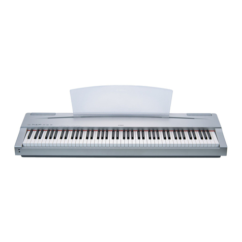
Yamaha P-120 User manual

SERVICE MANUAL
HAMAMATSU, JAPAN
1.702K-5011 Printed in Japan ’01, 09
PK 000344
CONTENTS(目次)
SPECIFICATIONS(総合仕様)........................................................... 3
PANEL LAYOUT(パネルレイアウト)............................................... 4
CIRCUIT BOARD LAYOUT(ユニットレイアウト)........................... 6
DISASSEMBLY PROCEDURE(分解手順)....................................... 7
LSI PIN DESCRIPTION(LSI端子機能表)....................................... 15
IC BLOCK DIAGRAM (ICブロック図)........................................... 16
CIRCUIT BOARDS(シート基板図)................................................ 18
TEST PROGRAM(テストプログラム)........................................... 26
MIDI IMPLEMENTATION CHART..................................................... 36
PARTS LIST
BLOCK DIAGRAM(ブロックダイアグラム)
OVERALL CIRCUIT DIAGRAM(総回路図)
P-120 20011015-160000
P-120S
L-120 20011015-9000
L-120S
ELECTRONIC PIANO
P-120/P-120S
This document is printed on chlorine free (ECF) paper with soy ink.
このサービスマニュアルはエコパルプ
(ECF:無塩素系漂白パルプ)を使用しています。
このサービスマニュアルは
大豆油インクで印刷しています。
•OPTION ((
((
(別売品)別売品)
別売品)別売品)
別売品)
L-120/L-120S KEYBOARD STAND
キーボードスタンド
P120

2
P-120/P-120S
IMPORTANT NOTICE
This manual has been provided for the use of authorized Yamaha Retailers and their service personnel. It has been assumed that
basic service procedures inherent to the industry, and more specifically Yamaha Products, are already known and understood by the
users, and have therefore not been restated.
WARNING: Failure to follow appropriate service and safety procedures when servicing this product may result in per-
sonal injury, destruction of expensive components and failure of the product to perform as specified. For
these reasons, we advise all Yamaha product owners that all service required should be performed by an
authorized Yamaha Retailer or the appointed service representative.
IMPORTANT: This presentation or sale of this manual to any individual or firm does not constitute authorization, certifica-
tion, recognition of any applicable technical capabilities, or establish a principal-agent relationship of any
form.
The data provided is believed to be accurate and applicable to the unit(s) indicated on the cover. The research engineering, and
service departments of Yamaha are continually striving to improve Yamaha products. Modifications are, therefor, inevitable and
changes in specification are subject to change without notice or obligation to retrofit. Should any discrepancy appear to exist, please
contact the distributor's Service Division.
WARNING: Static discharges can destroy expensive components. Discharge any static electricity your body may have
accumulated by grounding yourself to the ground bus in the unit (heavy gauge black wires connect to this
bus).
IMPORTANT: Turn the unit OFF during disassembly and parts replacement. Recheck all work before you apply power to
the unit.
WARNING: CHEMICAL CONTENT NOTICE!
The solder used in the production of this product contains LEAD. In addition, other electrical / electronic and / or plastic (where
applicable) components may also contain traces of chemicals found by the California Health and WelfareAgency (and possibly other
entities) to cause cancer and / or birth defects or other reproductive harm.
DO NOT PLACE SOLDER, ELECTRICAL / ELECTRONIC OR PLASTIC COMPONENTS IN YOUR MOUTH FOR ANY REASON
WHAT SO EVER!
Avoid prolonged, unprotected contact between solder and your skin! When soldering, do not inhale solder fumes or expose eyes to
solder / flux vapor!
If you come in contact with solder or components located inside the enclosure of this product, wash your hands before handling food.
IMPORTANT NOTICE FOR THE UNITED KINGDOM
Connecting the Plug and Cord
WARNING: THIS APPARATUS MUST BE EARTHED
IMPORTANT: The wires in this main lead are coloured in accor-
dance with the following code:
GREEN-AND-YELLOW: EARTH
BLUE: NEUTRAL
BROWN: LIVE
As the colours of the wires in the main lead of this apparatus may not
correspond with the coloured markings identifying the terminals in your
plug, proceed as follows:
The GREEN-and-YELLOW wire must be connected to the terminal in the
plug that is marked with the letter E or the safety earth symbol (or coloured
GREEN or GREEN-and-YELLOW).
The BLUE wire must be connected to the terminal that is marked with the
letter N (or coloured BLACK).
The BROWN wire must be connected to the terminal that is marked with
the letter L (or coloured RED).
This applies only to products distributed by Yamaha Kemble Music (U. K.) Ltd.
■■
■■
■WARNING
Components having special characteristics are marked and
must be replaced with parts having specification equal to those
originally installed.
印の商品は、安全を維持するために重要な部品です。交換する
場合は、安全のため必ず指定の部品をご使用下さい。
3
P-120/P-120S
■ SPECIFICATIONS(総合仕様)
KEYBOARD 88 (A-1 ~ C7)
POLYPHONY 64 NOTES MAX
VOICE SELECTORS 14 Voices + Variation for each voice
REVERB ROOM, HALL1, HALL2, STAGE
EFFECT CHORUS, PHASER, TREMOLO, DELAY
TOUCH SENSITIVE HARD, MEDIUM, SOFT, FIXED
SONG CONTROLS PRESET, USER 1/2/3, TRACK 1/2, START/STOP, REC
PEDAL CONTROLS SUSTAIN (HALF PEDAL SUPPORT), AUX PEDAL
OTHER CONTROLS MASTER VOLUME, BRILLIANCE, DEMO, METRONOME START/STOP,
TEMPO/FUNCTION # ▲/▼, -/NO ▼, +/YES ▲,
SPLIT, TRANSPOSE, LED Display
JACK/CONNECTORS AUX OUT (LEVEL FIXED) L/R, AUX OUT L/L+R, SUSTAIN PEDAL, AUX
PEDAL, PHONES x 2, TO HOST, MIDI IN/OUT, DC IN 12V
OUTPUT IMPEDANCE 600Ω
MAIN AMPLIFIER 12.5W x 2
SPEAKER OVAL (12cm x 6cm) x 2
POWER SUPPLY AC ADAPTER PA-300
POWER CONSUMPTION 26W
DIMENSIONS (WxDxH) 1354 x 334 x 137 mm (53-1/4" x 13" x 5-1/2")
WEIGHT 18.6 kg (41 lbs.)
鍵盤 88鍵(A-1〜C7)
音源 AWMダイナミックスステレオサンプリング
最大同時発音数 最大64音
音色数 14+各音色バリエーション
効果 ブリリアンス、リバーブ(ルーム/ホール1/ホール2/ステージ)、エフェクト
(コーラス/フェーザー/トレモロ/ディレイ)
ボリューム マスターボリューム
コントロール デュアル、スプリット、メトロノーム、トランスポーズ、タッチ(ハード/ミ
ディアム/ソフト/フィックス)、各種ファンクション、スピーカーON/OFF
レコーダー 2トラック録音/再生(3曲)、テンポ、シンクロスタート
ペダル サステイン(ハーフペダル対応)、多機能割り当て
デモ 各音色デモ曲、ピアノ曲50曲
付属端子 AUXOUT(LEVELFIXED)(L,R)端子、AUXOUT(L/L+R,R)端子、SUSTAIN
PEDAL端子、AUXPEDAL端子、PHONES(ヘッドフォン)端子×2、TOHOST
端子、MIDI端子(IN、OUT)
出力インピーダンス 600Ω
メインアンプ 12.5W×2
スピーカー 楕円(12cm×6cm)×2
定格電源 電源アダプターPA-300
消費電力 26W
寸法[間口×奥行き×高さ] 1354mm×334mm×137mm
質量 18.6kg
付属品 電源アダプターPA-300、ペダル、譜面立て、取扱説明書、ピアノで弾く名曲50
選(楽譜集)、保証書

4
P-120/P-120S
■ PANELLAYOUT(パネルレイアウト)
씋씌씍씎
C0 D0 E0 F0 G0 A0 B0 C1 D1 E1 F1 G1 A1 B1 C2 D2 E2 F2 G2 A2 B2 C3 D3 E3 F3 G3 A3 B3 C4 D4 E4 F4 G4 A4 B4 C5 D5 E5 F5 G5 A5 B5 C6 D6 E6 F6 G6 A6 B6 C7
B-1A-1
쐅쐈쐉씈
씉
씊
● Top Panel
[MASTER VOLUME] Control
[BRILLIANCE] Control
[DEMO] Button
[METRONOME START/STOP] Button
[TEMPO FUNCTION # ▲▼] Button
[LED Display]
[-/NO]/[+/YES] Button
[PRESET] Button
[USER1] [USER2] [USER3] Button
쐅[TRACK1] Button SONG
쐈[TRACK2] Button
쐉[START/STOP] Button
씈[REC] Button
씉VOICE SELECT Button
씊[SPLIT] Button
씋[REVERB] Button
씌[EFFECT] Button
씍[TOUCH] Button
씎[TRANSPOSE] Button
[MASTERVOLUME](マスターボリューム)コントロール
[BRILLIANCE](ブリリアンス)コントロール
[DEMO](デモ)ボタン
[METRONOMESTART/STOP](メトロノームスタート/ストップ)ボタン
[TEMPOFUNCTION#▲▼](テンポ/ファンクション)ボタン
(LEDディスプレイ)
[-/NO]/[+/YES]ボタン
[PRESET](プリセット)ボタン
[USER1][USER2][USER3](ユーザー1,ユーザー2,ユーザー3)ボタン
[TRACK1](トラック1)ボタン SONG
[TRACK2](トラック2)ボタン
[START/STOP](スタート/ストップ)ボタン
[REC](レコード)ボタン
VOICESELECT(音色)ボタン
[SPLIT](スプリット)ボタン
[REVERB](リバーブ)ボタン
[EFFECT](エフェクト)ボタン
[TOUCH](タッチ)ボタン
[TRANSPOSE](トランスポーズ)ボタン

5
P-120/P-120S
● Side Panel
쐅쐈
[SUSTAIN PEDAL] Jack
[AUX PEDAL] Jack
MIDI [IN] [OUT] Connector
[HOST SELECT] MIDI/PC2/PC1/Mac Switch
[TO HOST] Connector
[DC IN] Jack
[ STANDBY/ ON] Switch
[AUX OUT] L, R Pin jacks
[AUX OUT] L/L+R, R Phone Jack
쐅[Speaker] NORMAL (HP, SW)/ON/OFF Switch
쐈[Phones] Jack
[SUSTAINPEDAL](サステイン)端子
[AUXPEDAL](AUXペダル)端子
MIDI[IN][OUT]端子
[HOSTSELECT]MIDI/PC2/PC1/Mac(ホストセレクト)スイッチ
[TOHOST]端子
[DCIN]端子
[STANDBY/ON](スタンバイ/オン)スイッチ
[AUXOUT]L,Rピン端子
[AUXOUT]L/L+R,R標準フォーン端子
[Speaker]NORMAL(HP,SW)/ON/OFF(スピーカー)スイッチ
[PHONES](ヘッドフォン)端子

6
P-120/P-120S
■ CIRCUIT BOARD LAYOUT(ユニットレイアウト)
Bottom View
Top & Front View
Side Cover Assembly Inner View
AMP
DM
PNR
SW
GHDcl SW L GH-D_SW H
PNL
AJACK
AJACK
DJACK
DJACK
120
130 140
210
180
220
170 160150
160
170
180
190 190 200
210 220
Ref No.
120
130
150
160
170
180
190
200
210
220
CONNECTOR ASSEMBLY
KRD-KRD 8P-L:350
PN1 9P
PN2 13P
DACOUT 4P-L:940
VR 8P-L:670
AMP 9P-L:1000
KRD-KRD 11P-L:550
SP-LEFT 2P
SP-RIGHT 2P
BATTERY 1 5P
BATTERY 2 4P
DM-CN3
DM-CN2
DM-CN1
DM-CN4
AJACK-CN104
AJACK-CN106
DM-CN6
AMP-CN603
AMP-CN604
DM-CN5
AJACK-CN103
GHDcl SW-L
PNL-CN102
PNR-CN202
PNL-CN101
PNR-CN201
AJACK-CN105
PNL-CN301
AMP-CN601
DJACK-CN1
SPEAKER (L)
SPEAKER (R)
AJACK-CN102
AMP-CN602
DESTINATION

7
P-120/P-120S
■ DISASSEMBLY PROCEDURE(分解手順)
* Lay the soft cloth under the unit to protect it from
being scratched.
1.
Top Board Assembly (Time required: about 2min)
* Apply a masking tape to the edge of the top board
assembly to protect it from being scratched.
1-1 Turn the unit backward to get up and remove the
nine (9) screws marked [280]. (Fig.1, Fig.2)
1-2 Lay down the unit again, slide the top board
assembly backward until it stops, and lift it out.
(Fig.3)
(Fig.1)
[280]
Keybed Assembly
Bottom Side
1
2
* 作業を行うときは、本体に傷がつくのを防ぐた
め、やわらかい布などを敷いてください。
1. 屋根Ass'y( 所要時間:約2分)
* 屋根Ass'yのふちにマスキングテープなどを貼
り、傷がつくのを防止してください。
1-1 本体のフロント部分を持ち上げて起こし、[280]
のネジ9本をはずします。(Fig.1,Fig.2)
1-2 本体を元に戻し、屋根Ass'yを後方に止まるまで
ずらし、持ち上げて外します。(Fig.3)
(Fig.2)
(Fig.3)
[280]: Bind Head Screw 4.0X16 MFZN2BL (EG340110) +バインド小ネジ

8
P-120/P-120S
2. DM Circuit Board (Time required: about 3min)
2-1 Remove the top board assembly. (See procedure.1)
2-2 Remove the two (2) screws marked [290a] and the
two (2) screws marked [320]. The DM circuit
board can then be removed. (Fig.4)
* When reinstalling the top board assembly, apply a
masking tape to the shaded portion in the illustra-
tion to protect the side cover assembly from being
scratched. (Fig.5)
3.
AMP Circuit Board (Time required: about 3min)
3-1 Remove the top board assembly. (See procedure.1)
3-2 Remove the six (6) screws marked [290b]. The
AMP circuit board can then be removed. (Fig.4)
4.
PNR Circuit Board (Time required: about 3min)
4-1 Remove the top board assembly. (See procedure.1)
4-2 Remove the nine (9) screws marked [130a]. The
PNR circuit board can then be removed. (Fig.6)
2. DMシート(所要時間:約3分)
2-1 屋根Ass'yを外します。(1項参照)
2-2 [290a]のネジ2本と[320]のネジ2本を外し、DM
シートを外します。(Fig.4)
* 屋根Ass'yを取り付けるとき、腕木Ass'yに傷が
つくのを防ぐため、図中の網掛け部分にマスキ
ングテープを貼ってください。(Fig.5)
3. AMPシート(所要時間:約3分)
3-1 屋根Ass'yを外します。(1項参照)
3-2 [290b]のネジ6本を外し、AMPシートを外しま
す。(Fig.4)
4. PNRシート(所要時間:約3分)
4-1 屋根Ass'yを外します。(1項参照)
4-2 [130a]のネジ9本を外し、PNRシートを外します。
(Fig.6)
PNL PNR
Panel Angle
[240a]
[300] [130a][130b]
[130a][130b][240b]
Top Board Assembly (Bottom veiw)
(Fig.6)
[130]: Bind Head Tapping Screw-B 3.0X8 MFZN2Y (EP600250) +バインドBタイト
[240]: Bind Head Tapping Screw-1 3.5X12 MFZN2BL (EP030340) +バインドTP1種
[300]: Bind Head Tapping Screw-B 3.0X10 MFZN2BL (EP600140) +バインドBタイト
Speaker L
Top Board Assembly
[290a] [320][320] [290b]
[30d][30d]
Speaker R
AMP
DM
ROM (C Version Only)
(Fig.4)
[30d]: Hexagonal Nut MFZN2Y (03760120) 六角ナット
[290]: Bind Head Tapping Screw-B 3.0X6 MFZN2Y (EP600130) +バインドBタイト
[320]: Bind Head Screw-B 3.0X8 MFZN2BL (EP600190)+バインドBタイト
[80]
[80]: Slide Knob (V8085100) ツマミ(スライド)
(Fig.5)

9
P-120/P-120S
5.
PNL Circuit Board (Time required: about 3min)
5-1 Remove the two (2) slide knobs marked [80].
(Fig.5)
5-2 Remove the top board assembly. (See procedure.1)
5-3 Remove the two (2) screws marked [240a] and two
(2) screws marked [300]. The panel angle assembly
can then be removed. (Fig.6)
5-4 Remove the eight (8) screws marked [130b] and
the screw marked [240b]. The PNL circuit board
can then be removed. (Fig.6)
6. Speakers (Time required: about 3min)
6-1 Remove the top board assembly. (See procedure.1)
6-2 Remove the four (4) hexagonal nuts marked [30d].
The speaker can then be removed. (Fig.4)
* Both of the right and the left speaker can be
removed by the same procedure.
7.
Keyboard Assembly (Time required: about 4min)
7-1 Remove the top board assembly. (See procedure.1)
7-2 Remove the two (2) screws marked [250] and the
nine (9) screws marked [260]. The keyboard
assembly can then be removed. (Fig.7)
* Hold the central area of the frame to prevent it
from twisting and turn the keyboard assembly
forward to get up. (Fig.9)
* When moving the keyboard assembly, the screws
marked [230] which fix the side cover assembly
may stand in the way. (Fig.10)
Then lift the keyboard assembly fitly to avoid those
screws.
* To remove the keyboard assembly easily, slide it
rearward, over the center of the side cover, to the
area hiding under the top board assembly. (Fig.8)
5. PNLシート(所要時間:約3分)
5-1 [80]のスライドツマミ2個を外します。(Fig.5)
5-2 屋根Ass'yを外します。(1項参照)
5-3 [240a]のネジ2本と、[300]のネジ2本を外し、パ
ネル補強金具を外します。(Fig.6)
5-4 [130b]のネジ8本と[240b]のネジを外し、PNL
シートを外します。(Fig.6)
6. スピーカ(所要時間:約3分)
6-1 屋根Ass'yを外します。(1項参照)
6-2 [30d]の六角ナット4個を外し、スピーカを外し
ます。(Fig.4)
* 左右のスピーカとも、同じ手順で外すことがで
きます。
7. GHDcl鍵盤Ass'y( 所要時間:約4分)
7-1 屋根Ass'yを外します。(1項参照)
7-2 [250]のネジ2本と[260]のネジ9本を外し、棚板か
ら鍵盤Ass'yを外します。(Fig.7)
* GHDcl鍵盤Ass'yを外すときは、鍵盤ユニットが
ねじれないようにフレーム中央を持ち上げ、鍵
盤ユニットを縦に起こします。(Fig.9)
* 鍵盤取り外しおよび取り付けのとき、腕木Ass'y
を固定している[230]のネジがフレームに引っか
かります。(Fig.10)
その場合は必要に応じて鍵盤Ass'yを持ち上げ、
前後に動かします。
* 鍵盤Ass'yは左右の腕木よりも広いため、十分に
後方へずらさないと外すことができません。(Fig.8)
腕木中央より後方(屋根Ass'yに隠れている部分)まで
ずらすことにより、取り外しが容易になります。
GHD Keyboard Assembly
[250] [250][260]
(Fig.7)
[250]: Bind Head Tapping Screw-1 4.0X14 MFZN2Y (EP040230) +バインドTP1種
[260]: Pan Head Screw 5.0X25 MFZN2Y PW (VV040700) +ナベ小ネジ

10
P-120/P-120S
8.
DJACK Circuit Board (Time required: about 5min)
8-1 Remove the top board assembly. (See procedure.1)
8-2 Remove the keyboard assembly. (See procedure.7)
8-3 Remove the four (4) screws marked [230a] and the
screw marked [360] from the bottom of the unit.
The side cover assembly L can then be removed.
(Fig.11)
8-4 Remove the three (3) screws marked [240a]. The
DJACK circuit board can then be removed. (Fig.12)
8. DJACKシート(所要時間:約5分)
8-1 屋根Ass'yを外します。(1項参照)
8-2 鍵盤Ass'yを外します。(7項参照)
8-3 本体の底面より[230a]のネジ4本と[360]のネジ1
本を外し、腕木Ass'yLを外します。(Fig.11)
8-4
[240a]のネジ3本を外し、DJACKシートを外します。
(Fig.12)
Keyboard assembly
(GHD鍵盤Ass’y)
Keyboard assembly
(GHD鍵盤Ass’y)
(Fig.9)
Keyboard Bottom sideKeyboard Bottom side
Side Cover AssemblySide Cover Assembly
干渉部分
(Fig.10)
[240a]
[240b]
Side Cover Assembly (L)
(Fig.12)
[240]: Bind Head Tapping Screw-B 3.0X8 MFZN2Y (EP600250)
+バインドBタイト
(Fig.8)

11
P-120/P-120S
9. AJACK Circuit Board, SW Circuit Board
(Time required: about 6min)
9-1 Remove the top board assembly. (See procedure.1)
9-2 Remove the keyboard assembly. (See procedure.7)
9-3 Remove the side cover assembly L. (See proce-
dure.8-3)
9-4 Remove the three (3) screws marked [240b]. The
AJACK circuit board Assembly can then be re-
moved. (Fig.12)
9-5 Remove the two (2) screws marked [100c]. The SW
circuit board can then be removed. (Fig.13)
9-6 Pull out the push knob marked [90]. (Fig.14)
10.
Side Cover Assembly R (Time required: about 5min)
10-1 Remove the top board assembly. (See procedure.1)
10-2 Remove the keyboard assembly. (See procedure.7)
10-3 Remove the three (3) screws marked [230b] from
the bottom of the unit. (Fig.11)
10-4 Remove the screw marked [270] and the two (2)
screws marked [310] from the top of the unit. The
side cover assembly R can then be removed.
(Fig.11)
9. AJACKシート、SWシート(所要時間:約6分)
9-1 屋根Ass'yを外します。(1項参照)
9-2 鍵盤Ass'yを外します。(7項参照)
9-3 腕木Ass'yLを外します。(8-3項参照)
9-4 [240b]のネジ3本を外し、AJACKシートAss'yを
外します。(Fig.12)
9-5 [100c]のネジ2本を外し、SWシートを外しま
す。(Fig.13)
9-6 [90]のプッシュツマミを手前に引いて外します。
(Fig.14)
10. 腕木Ass'yR(所要時間:約5分)
10-1 屋根Ass'yを外します。(1項参照)
10-2 鍵盤Ass'yを外します。(7項参照)
10-3 本体の底面より[230b]のネジ3本を外します。
(Fig.11)
10-4 本体上部より[270]のネジ1本と[310]のネジ2本を
外し、腕木Ass'yRを外します。(Fig.11)
[230b]
[270]
[310] x 2
[230a]
[360] [270]
Side Cover Assembly (L) Side Cover Assembly (R)
Bottom Side Upper Side
Keybed Assembly
(Fig.11)
[230]: Bind Head Tapping Screw-B 4.0X20 MFZN2BL (VS205900) +バインドBタイト
[270]: Bind Head Tapping Screw-1 3.5X12 MFZN2BL (EP030340) +バインドTP1種
[310]: Bind Head Tapping Screw-B 3.0X6 MFZN2Y (EP600130) +バインドBタイト
[360]: Bind Head Screw 4.0X20 BL (VB403600) +バインド小ネジ
AJACK Circuit BoardAJACK Circuit Board
SW Circuit Board[100c]
(Fig.13)
[100c]: Bind Head Tapping Screw-B 3.0X10 MFZN2BL
(EP600140)+バインドBタイト (Fig.14)
[90]: Knob (VQ218800) プッシュツマミ
Circuit BoardCircuit Board
[90][90]
SW
Circuit BoardCircuit Board
AJACK

12
P-120/P-120S
11.
Front Rail Assembly (Time required: about 8min)
11-1 Remove the top board assembly. (See procedure.1)
11-2 Remove the keyboard assembly. (See procedure.7)
11-3 Remove the side cover assembly (L) and the side
cover assembly (R). (See procedure.8-3, proce-
dure.10)
11-4 Remove the five (5) screws marked [270]. The
front rail assembly can then be removed. (Fig.11)
Keyboard assembly
(GHDcl鍵盤Ass’y)
GHDcl SW L Circuit board
(GHDcl SW シートL)[260a] x 7 [260b] x 10
GH-D SW H Circuit board
(GH-D_SW シートH)
[260]: Bind Head Tapping Screw-P 3.0X10 MFZN2 (VT413400)
+バインドP タイト
12. Disassembling the GHDcl Keyboard
(Time required: about 20 min)
* After inserting a round stick (Rod: TX000670)
between the frame and keys, remove the circuit
boards. (Fig.17)
12-1 Remove the keyboard assembly. (See Procedure 7)
12-2 GHDcl SW L circuit board.
Remove the seven (7) screws marked [260a]. The
GHDcl SW L circuit board can then be removed.
(Fig.15)
12-3 GH-D_SW H circuit board.
Remove the ten (10) screws marked [260b]. The
GH-D_SW H circuit board can then be removed.
(Fig.15)
* Keys can be removed without removing the circuit
boards.
* The rubber contact can be removed, after GHDcl
SW L circuit board and GH-D_SW H circuit board
are removed.
12-4 White Key
Insert a thin plate between the white keys, near the
triangle mark around the fulcrum of the key, and
press down the stopper marked [A] to remove the
key. (Fig.16 and 17)
12.GHDcl鍵盤の分解(所要時間:約20 分)
※ シートを外す前に、シーソードーム(接点ゴム)を
歪ませないように、フレームとハンマーの間に丸
棒(ロッド:TX000670)を挿入しておきます。
(fig.17)
12-1 GHDcl鍵盤Ass’yを、本体から外します。
(7項参照)
12-2 GHDclSWシートL
[260a]のネジ7本を外し、GHDclSWシートLを
外します。(fig.15)
12-3 GH-DSWシートH
[260b]のネジ10本を外し、GH-DSWシートH
を外します。(fig.15)
※ 白鍵と黒鍵は、GHDc1SWシートLとGH-DSW
シートHを外さなくても、外すことができます。
※ GHDclSWシートLとGH-DSWシートHシート
を外すと、シーソードーム(接点ゴム)を外すこ
とができます。
12-4 白鍵
薄いプレート状のものを、鍵盤の間に挿入して
(白鍵支点付近の三角マークの示す方向の隙間)
[A]のストッパーを押し下げ、白鍵盤フックが
外れるまで白鍵を前方にずらし、持ち上げて外
します。(fig.16,17)
(Fig.15)
Thin metal plate etc.
(薄い金尺等)
Triangle mark
(三角マーク
)
(Fig.16)
[B]
[C]
[D]
Rod : TX000670
(丸棒)
White key
(白鍵)
Spring
(スプリング)
(Fig.17)
11. 口棒Ass'y( 所要時間:約8分)
11-1 屋根Ass'yを外します。(1項参照)
11-2 鍵盤Ass'yを外します。(7項参照)
11-3 腕木Ass'yL,Rを外します。(8-3項、10項参照)
11-4 [270]のネジ5本を外し、口棒Ass'yを外します。
(Fig.11)

13
P-120/P-120S
13. Assembling the GHDcl Keyboard
13-1 Hammer of White (Black) Key
Place the keyboard assembly upside down, insert a
hammer assembly into the frame, and put the
stopper L88 on. (Fig.20)
* There are four kinds of hammers that differ in
weight.
13-2 Key Spring
Place the keyboard assembly right side up, and fix
a key spring to the frame by setting it at the slit
and pushing it down once. (Fig.21)
* Be careful of the direction of the spring.
13.GHDcl鍵盤の組立て
13-1 ハンマー白鍵(黒鍵)
GHD鍵盤の裏側より、ハンマー白鍵(黒鍵)をフ
レームに差し込み、ストッパーL88を取り付け
ます。(Fig.20)
13-2 スプリング
GHD鍵盤を表側にして、端が2本に分かれてい
るスプリングの先をハンマー白鍵(黒鍵)の切り
込みに合わせて、一度下に押し込んでフレーム
のフックに取り付けます。(Fig.21)
※ スプリングの向きに注意してください。スプリ
ングは、"<"の字形状をしています。"Λ"のよ
うに上側が凸になるように取り付けます。
※ このとき、白鍵を前方にずらしすぎてスプリン
グを傷めないように、十分注意して作業をして
ください。
※
黒鍵は、両隣の白鍵を外すと、外すことができます。
12-5 ハンマー白鍵
白鍵を外し、スプリングを一度下に押し込み、
フックから外します。(fig.18)
GHD鍵盤を裏側にし、ストッパーL88をはがし
てハンマー白鍵を外します。(fig.19)
※ ハンマー黒鍵もハンマー白鍵と同じようにして
外すことができます。
* Take care not to damage the key spring when
removing a key.
* A black key can be removed after both adjacent
white keys have been removed.
12-5 Hammer, White Key
After a key has been removed, push the key spring
down once to take it out of the hook. (Fig.18)
Place the GH keyboard assembly upside down and
peel away then stopper L88. The hammer of the
white key can then be removed. (Fig.19)
* The hammer of a black key can be removed in the
same manner.
Upside
(上側)
Spring
(スプリング
)
Frame
(フレーム)
Hook
(フック)
(Fig.21)
(Fig.20)
Stopper L88
(ストッパーL88)
Hammer, white key
(ハンマー白鍵)
Slit
(切り込み
)
Frame
(フレーム)
Stopper L88
(ストッパーL88)
Hammer, white key
(ハンマー白鍵)
Spring
(スプリング)
Hook
(フック
)
(Fig. 18)
(Fig.19)

14
P-120/P-120S
[E]
[F]
White key
(白鍵)
Key guide
(キーガイド)
Key spring
(スプリング)
(Fig.22)
13-3 White (Black) Key
After a key has been fit to part [F] and the key
guide, make sure that the spring is fixed to the key.
Then press part [E] of the key down. (Fig.22)
13-4 GHDcl SW L circuit board.
Tighten the seven [7] screws marked [260a] to fix
the GHDcl SW L circuit board. (Fig.15)
13-5 GH-D_SW H circuit board.
Tighten the ten [10] screws marked [260b] to fix
the GH-D_SW H circuit board. Set the slits of the
rubber contact at the marks on the frame. (Fig.15)
13-3 白鍵(黒鍵)
[C]部とキーガイドに白鍵(黒鍵)をくわえさ
せ、鍵盤の支点内側のバネ受け部に、スプリン
グが確実に入っていることを確認したら、[B]
部の上を下方向にゆっくり押し込んで取り付け
ます。(Fig.22)
13-4 GHDclSWシートL
シーソードーム(接点ゴム)をフレーム裏側のス
リット部分にはめ込み、[260a]のネジ7本を取
り付けてGHDclSWシートLを取り付けます。
(Fig.15)
13-5 GH-DSWシートH
シーソードーム(接点ゴム)をフレーム裏側のス
リット部分にはめ込み、[260b]のネジ10本を取
り付けてGH-DSWシートHを取り付けます。
(Fig.15)
■ LSI PIN DESCRIPTION(LSI端子機能表)
CONTENTS(目次)
● HG73C205AFD XU947C00 SWX00B (TONE GENERATOR)...................................... 15
● YMZ702-D XR632A00 KSN2 (Key Scanner)................................................................ 16

15
P-120/P-120S
PIN
NO. NAME I/O FUNCTION PIN
NO. NAME I/O FUNCTION
1 ICN I Initial clear 85 CMA3 O
2 RFCLKI I PLL Clock 86 CMA8 O Program address bus
3 TM2 I PLL Control 87 CMA2 O
4 AVDD_PLL Power supply 88 CRD O read signal
5 AVSS_PLL Ground 89 CMA1 O Program address bus
6 MODE0 I SWX dual mode 90 CUB O high byte effective signal
7 VCC7 Power supply 91 VCC91 Power supply
8 GND8 Ground 92 GHND92 Ground
9 XIN I crystal oscillator 93 CS1 O CS signal
10 XOUT O crystal oscillator 94 CMA0 O Program address bus
11 MODE1 I SWX separate mode 95 CLB O low byte effective signal
12 TEST0 I TEST pin 96 CMA12 O
13 TESTON I TEST pin 97 CMA11 O
14 AN0-P40 I A/D converter 98 CMA10 O Program address bus
15 AN1-P41 I A/D converter 99 CMA9 O
16 AN2-P42 I A/D converter 100 GND100 Ground
17 AN3-P43 I A/D converter 101 CWE O write signal
18 AVDD_AN Power supply 102 CMA16 O
19 AVSS_AN Ground 103 CMA15 O
20 TXD0 O for MIDI or TO-HOST 104 CMA14 O Program address bus
21 TXD1 O for MIDI 105 CMA13 O
22 EXCLK I Crystal oscillator 106 CMD8 I/O
23 SMD11 I/O 107 CMD7 I/O
24 SMD4 I/O 108 CMD9 I/O
25 SMD3 I/O 109 CMD6 I/O
26 SMD12 I/O 110 CMD10 I/O
27 SMD10 I/O 111 CMD5 I/O
28 SMD5 I/O Wave memory data bus 112 CMD11 I/O
29 SMD2 I/O 113 CMD4 I/O Program memory Data bus
30 SMD13 I/O 114 CMD12 I/O
31 SMD9 I/O 115 CMD3 I/O
32 SMD6 I/O 116 CMD13 I/O
33 SMD1 I/O 117 CMD2 I/O
34 SMD14 I/O 118 CMD14 I/O
35 VCC35 Power supply 119 VCC119 Power supply
36 GND36 Ground 120 GND115 Ground
37 SMD8 I/O 121 CMD1 I/O
38 SMD7 I/O Wave memory data bus 122 CMD15 I/O Program memory Data bus
39 SMD0 I/O 123 CMD0 I/O
40 SMD15 I/O 124 CMA21 O Program address bus
41 SOE O read signal 125 PDT15 I/O
42 SWE O write signal 126 PDT14 I/O
43 SRAS O RAS signal 127 PDT13 I/O
44 SCAS O CAS signal 128 PDT12 I/O SWX access data bus
45 REFRESH O REFRESH signal 129 PDT11 I/O
46 CS0 O CS signal 130 PDT10 I/O
47 SMA0 O 131 PDT9 I/O
48 SMA16 O Memory address bus 132 PDT8 I/O
49 VCC49 Power supply 133 VCC133 Power supply
50 GND50 Ground 134 GND134 Ground
51 SMA1 O 135 PDT7 I/O
52 SMA15 O 136 PDT6 I/O
53 SMA2 O 137 PDT5 I/O
54 SMA14 O 138 PDT4 I/O
55 SMA3 O Memory address bus 139 PDT3 I/O SWX access data bus
56 SMA13 O 140 PDT2 I/O
57 SMA4 O 141 PDT1 I/O
58 SMA12 O 142 PDT0 I/O
59 SMA5 O 143 VCA143 Power supply
60 GND60 Ground 144 GND144 Ground
61 VCC61 Power supply 145 PAD2 I
62 SMA11 O 146 PAD1 I SWX access address bus
63 SMA6 O 147 PAD0 I
64 SMA10 O 148 VCC148 Power supply
65 SMA7 O 149 GND149 Ground
66 SMA9 O 150 PCS I Chip select
67 SMA17 O 151 PWR I write enable
68 SMA8 O Memory address bus 152 PRD I read enable
69 SMA18 O 153 RXD0 I for Midi or TO-HOST
70 SMA19 O 154 RXD1 I for Midi or Key scan
71 SMA20 O 155 SCLKI I EXT Clock
72 SMA21 O 156 ADIN I A/D converter
73 SMA22 O 157 ADLR O A/D converter LR clock
74 SMA23 O 158 DO0 O DAC
75 CMA20 O Program address bus 159 DO1 O DAC
76 CMA19 O 160 SYSCLK O 1/2 clock
77 VCC77 Power supply 161 VCC161 Power supply
78 GND78 O Ground 162 GND162 Ground
79 CMA18 O 163 WCLK O for DAC LR clock
80 CMA17 O 164 QCLK O 1/12 clock
81 CMA5 O Program address bus 165 BCLK O IIS-DAC clock
82 CMA6 O 166 SYI I Synch signal
83 CMA4 O 167 IRQ0 I
84 CMA7 O 168 NMI I Interrupt request
● HG73C205AFD (XU947C00) SWX00B TONE GENERATOR DM : IC007, 008

16
P-120/P-120S
1
2
3
4
5
6
7
8
9
10
11
12
13
14
15
16
17
18
19
20
PIN NAME I/O FUNCTION PIN NAME I/O FUNCTION
NO. NO.
O
O
O
O
O
O
I
I
I
I
I
I
I
I
I
I
I
I
I
O
Key block (open drein)
First make contact
Second make contact
Crystal osc. input (4 MHz)
Crystal osc. output (4 MHz)
21
22
23
24
25
26
27
28
29
30
31
32
33
34
35
36
37
38
39
40
O
I
I
I
I
I
I
O
O
O
O
O
O
O
O
O
Ground
Power supply
Serial data
Acknowledge/mode select
Clock for serial data
Initial clear
Test mode
(L,L: normal mode, others: test)
Inhibit of serial clock
Key block (open drein)
Ground
Power supply
BK5
BK4
BK3
BK2
BK1
BK0
MK15
MK14
MK13
MK12
MK11
MK10
MK05
MK04
MK03
MK02
MK01
MK00
XIN
XOUT
GND
VDD
SO
ACK
XCK
/IC
TST1
TST2
XCKINH
BK14
BK13
BK12
BK11
BK10
BK9
BK8
BK7
BK6
GND
VDD
● YMZ702-D (XR632A00) KSN2 (Key Scanner) GHDcl SW L KSN2
■ IC BLOCK DIAGRAM(IC ブロック図)
1
2
3
4
5
6
7
A
A
Select
Enable
Output
Output
BB
CC
G2A G2A
G2B
G2B
G1 G1
Y7 Y7 Y5
Y4
Y3
Y2
Y1
Y0
Y6
16
15
14
13
12
11
10
Vcc
YO
Y1
Y2
Y3
Y4
Y5
8
GND 9Y6
DM: IC006
TC74HC138AFEL
(XW762A00)
3 to 8 Demultiplexer
I1
I2
I3
I4
I5
I6
I7
I8
GND
1 18
2 17
3 16
4 15
5 14
6 13
7 12
8 11
9 10
DM: IC004
O1
O2
O3
O4
O5
O6
O7
O8
COMMON
TD62083F-TP1
(
XN153A00
)
8ch Driver Array
VDD
OUT
1
2
34
5
NC
IN
VSS
DJACK: IC001
SC7SU04FEL
(XI348A00)
lnverter Gate
TC7S04F
(XM182A00)
Vcc
Y
1
2
34
5
IN B
IN A
GND
TC7S00F
(XG150A00)
NAND
DM: IC026
PCM69AU-3/TE2
(XV297A00)
DIGITAL-TO-ANALOG CONVERTER
1
2
3
4
5
6
7
19
18
17
16
15
14
20
LV
COM
NC
LI
OUT
SRVCAP
REFCAP
RI
OUT
DCOM
MC2
RDATA
BTCK
SYSCK
WDCK
LDATA
8
NC MC3
9 12
10 11
13
+V
A
RV
COM
MC1
ACOM +V
D
DM: IC10
TC7S32F
(XM588A00)
OR
Vcc
OUT
1
2
35
4
IN A
IN B
Vss
DM: IC025

17
P-120/P-120S
AMP: IC001
AMP: IC 002, 003
1
2
3
4
5
6
7
IN1
NF1
IN2
NF2
IN3
NF3
IN4
16
15
14
13
12
11
10
-Vcc
GND
+Vcc
OUT
-IN
10k
10k
47k
47k
47k540
540
540
540
540
540
47k
47k
47k +IN
NF5
8
NF4 9IN5
+-
+-
+-
+-
+-
+-
M5227P
(XF751A00)
5-Band Graphic Equalizer
1
2
3
4
5
6
7
1B
1A
1R
1DE
2R
2A
2B
16
15
14
13
12
11
10
Vcc
1D
1Y
1Z
2DE
2Z
2Y
8
GND 92D
DJACK: IC002
SN75C1168NST-E
(XU073A00)
Line Driver / Receiver
1
2
3
4-V
8
7
6
5
Output A +V
Non-Inverting
Input A
-DC Voltage Supply
+DC Voltage
Supply
Output B
Inverting
Input B
Non-Inverting
Input B
Inverting
Input A
+-
+-
DM: IC013, 022
AJACK: IC101, 102
PC4570G2
(XF291A00)
Dual Operational Amplifier
■ CIRCUIT BOARDS(シート基板図)
CONTENTS(目次)
● DM Circuit Board (X0566B0) ........................................................................................ 18
● AMP Circuit Board (X0519B0) ...................................................................................... 20
● AJACK Circuit Board (X0599A0) .................................................................................. 21
● DJACK Circuit Board (X0599A0) ..................................................................................23
● SW Circuit Board (X0599A0) ........................................................................................ 23
● PNR Circuit Board (X0520C0) ...................................................................................... 24
● PNL Circuit Board (X0520C0)....................................................................................... 25
Other manuals for P-120
1
This manual suits for next models
1
Table of contents
Other Yamaha Synthesizer manuals

Yamaha
Yamaha MOXF8 User manual

Yamaha
Yamaha S90 Instruction Manual

Yamaha
Yamaha CP7 User manual

Yamaha
Yamaha Harmony Director HD-300 Operating manual

Yamaha
Yamaha PF2000 User manual

Yamaha
Yamaha MOX6 User manual

Yamaha
Yamaha PSR-S650 User manual

Yamaha
Yamaha DX100 User manual

Yamaha
Yamaha EX7 Instruction Manual

Yamaha
Yamaha PF2000 User manual

Yamaha
Yamaha P-140 User manual

Yamaha
Yamaha MOTIF RACK ES User manual

Yamaha
Yamaha TX816 User manual

Yamaha
Yamaha P-150 User manual

Yamaha
Yamaha VL-1 User manual

Yamaha
Yamaha MOX8 User manual

Yamaha
Yamaha W5 User manual

Yamaha
Yamaha S90 User manual

Yamaha
Yamaha CS-15 User manual

Yamaha
Yamaha SHS-200 User manual