- 2 -
Note
TO BEGIN
Item of Caution
*Take care when using sharp or pointed objects or when
using bladed cutting tools. Place a heavy sheet of paper
under the paper you want to cut.
*Use glue and other adhesives only in well-ventilated
areas.
*When printing, use a slightly reduced font size as there
are many differences in dimensions depending on the
type of printer used.
Tools and materials needed
-Ruler -Scissors - Blade cutter or "Exacto-knife" -Awl or
other pointed tool (for making a folding crease) - Felt
pen - Pin set - Glue - Hand towel ( for cleaning your
fingers) - Dictionary or other heavy book ( to press the
papers flat)
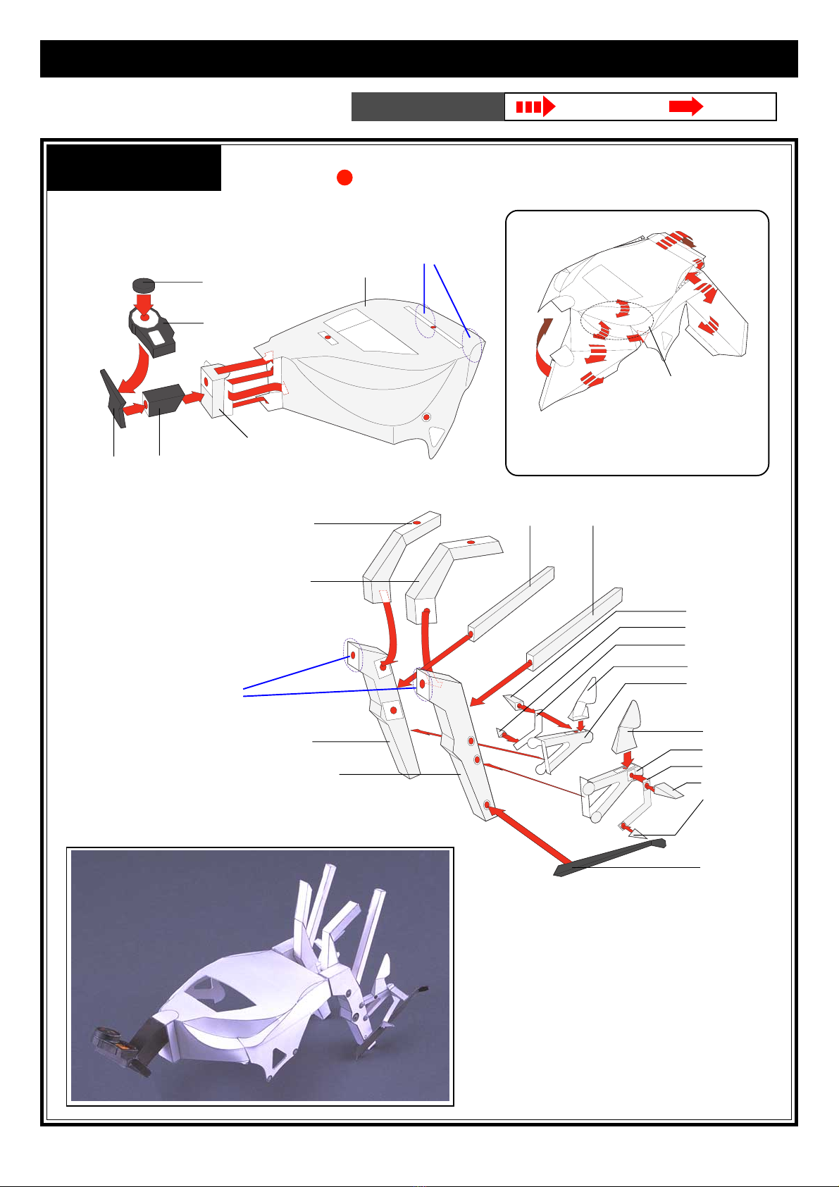
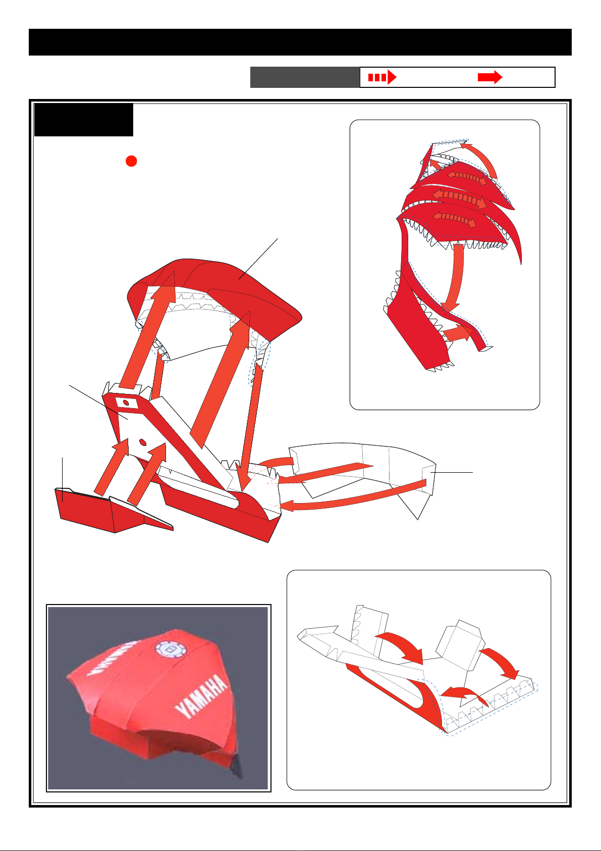
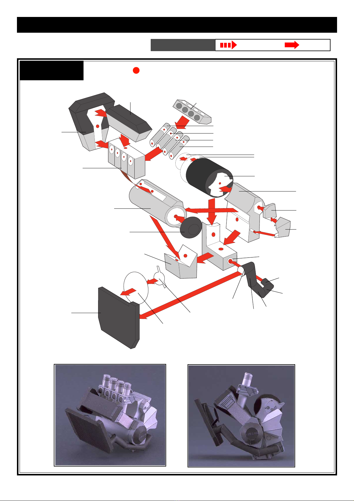
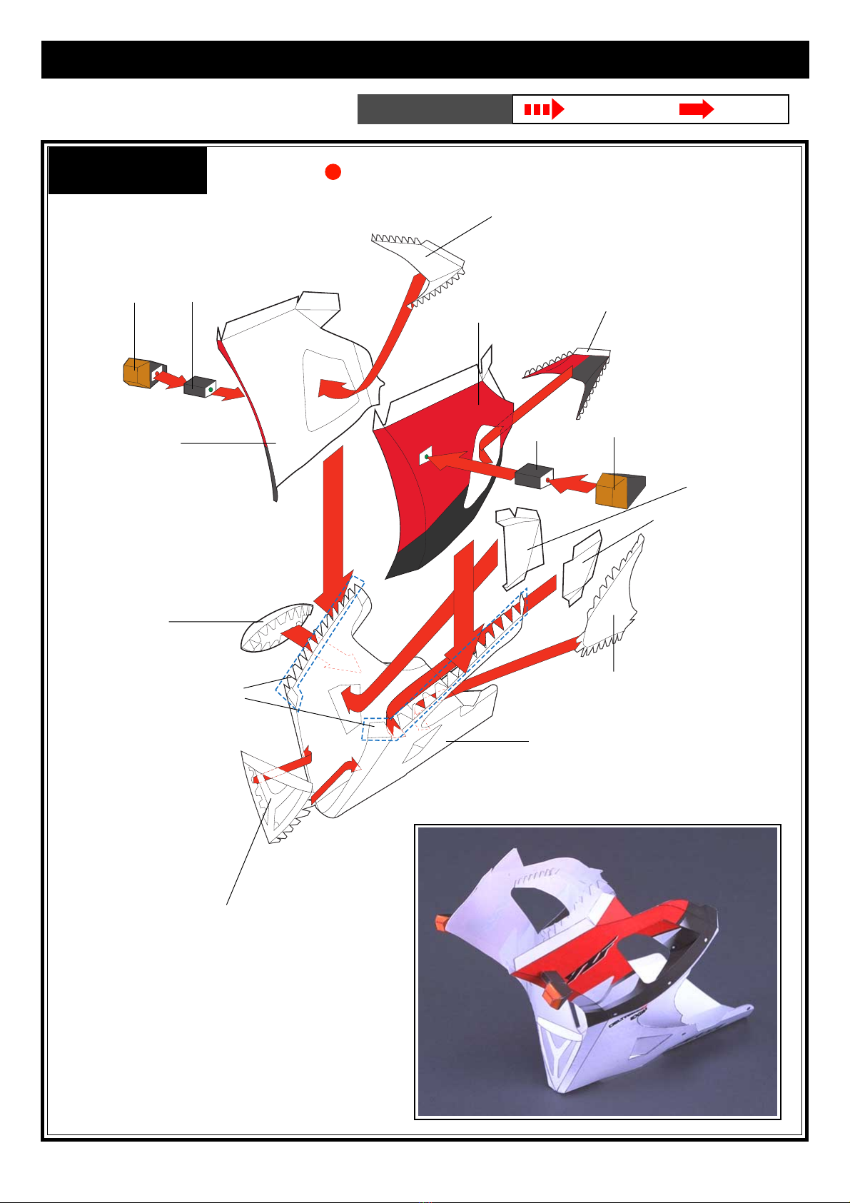
HOW TO ASSEMBLE
*Follow the working method and markings carefully.
*Cut carefully along the outter line with a cutting blade,
Exacto-knife or scissors.
*Cut carefully with a cutting blade, Exacto-knife or
scissors.
*For folding parts, first use an awl or other pointed
tool to make a light crease along the dotted or solid
line. This will make the folds straight.Avoid making
strong creases, as this will cause the paper to tear.
*As an adhesive, white, wood glue is recommended.
Avoid over application as this will cause the paper
to wrinkle.
*Before beginning assembly, test adhesive amounts
on extra paper.
*Occasionally, white spots will be apparent on folds
andcuts. Use amarker orpencil to fill-inthese spots.
It is recommended that this be done after each stage
of assembly because coloring becomes more diffi-
cult once parts are assembled.
One - point Advice
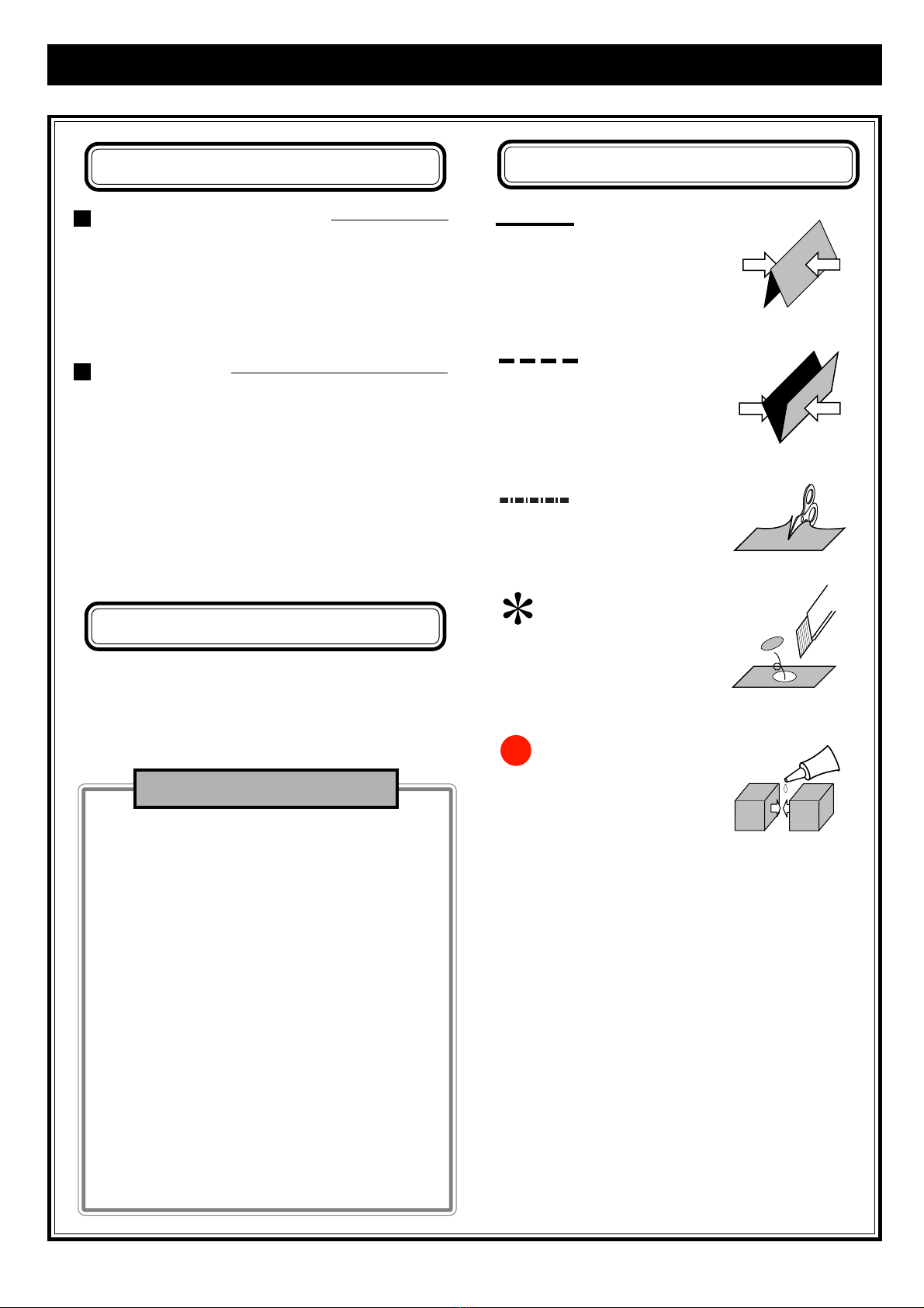
Basic working method and markings
Fold along these lines. The printed
surface should be on the outside of
the folded shape.
Solid lines
Dotted line
Fold along these lines. The printed
surface should be on the inside of
the folded shape.
Broken lines
Cut out parts marked with an as-
terisk(*).
Cut along these lines
Red dots are the reference positions
for gluing surfaces.