2
Note
Basic working method and markings
To begin
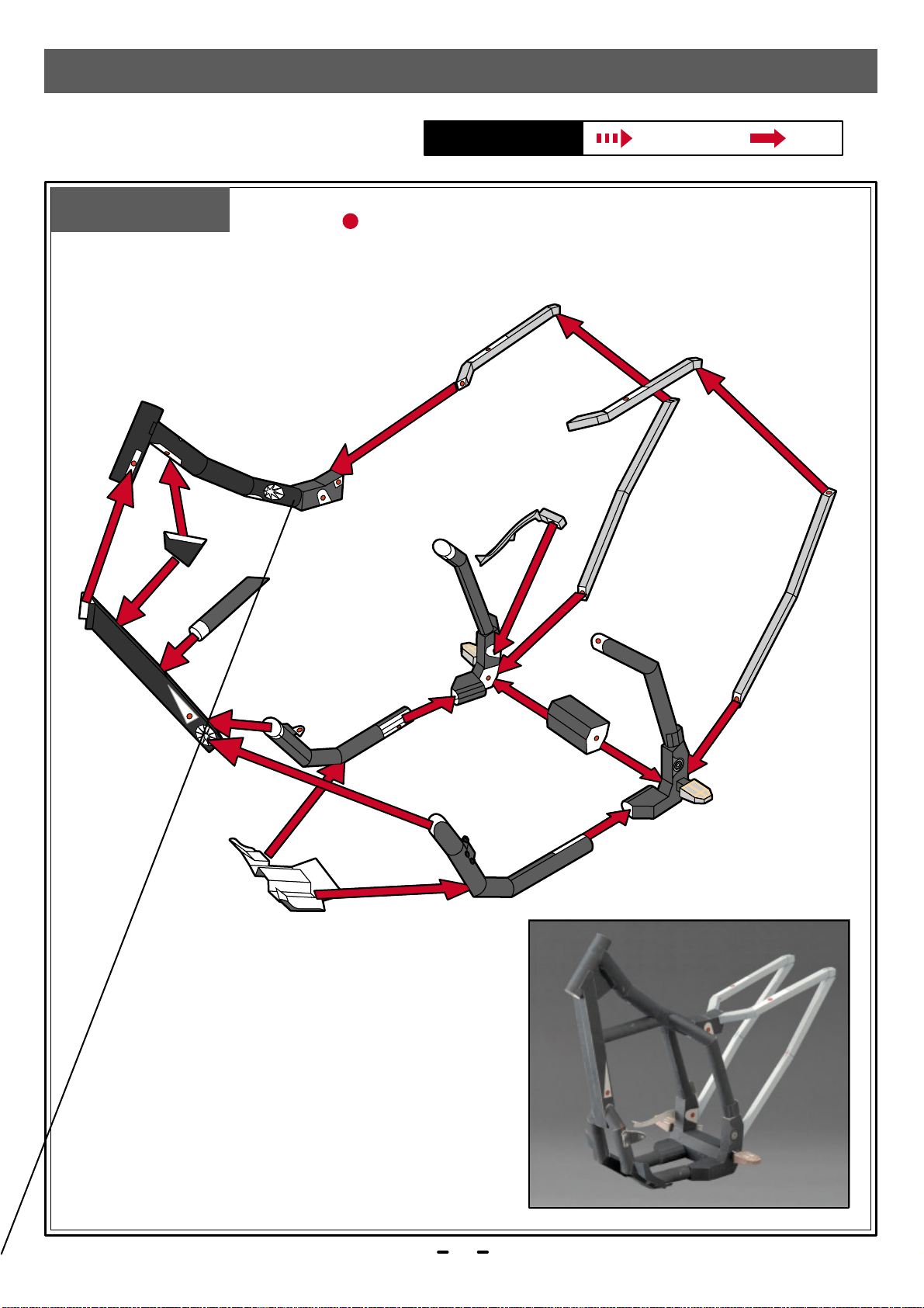
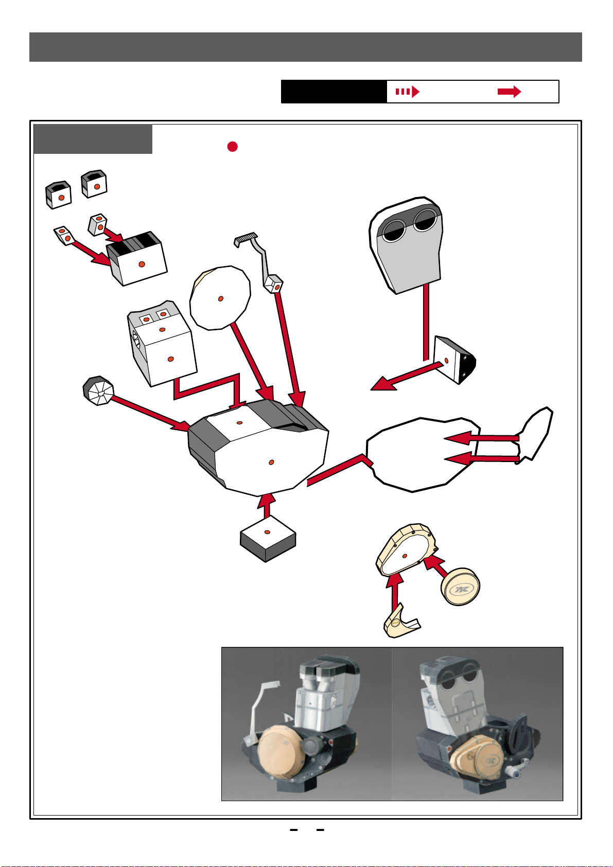
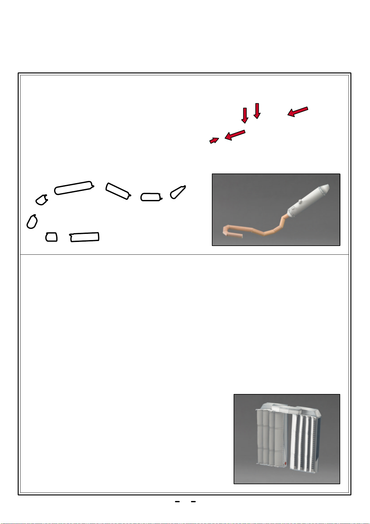
How to assemble
Tools and materials needed
Items of Caution
-Ruler - scissors - blade cutter or "Exacto-knife" - awl or
other pointed tool (for making a folding crease) - felt pen
- pin set - glue - hand towel ( for cleaning your fingers) -
dictionary or other heavy book ( to press the papers flat).
*Take care when using sharp or pointed objects or when
using bladed cutting tools. Place a heavy sheet of paper
under the paper you want to cut.
*Use glue and other adhesives only in well-ventilated
areas.
*When printing, use a slightly reduced font size.There
may be differences in dimensions, depending on the
type of printer used.
*Follow the working method and markings carefully.
*Cut carefully along the outter line with cutting blade,
Exacto-knife or scissors.
One - point Advice
*Before beginning assembly, test adhesive amounts
on extra paper.
*Cut carefully with cutting blade, Exacto-knife or
scissors.
*Occasionally, white spots will be apparent on folds
and cuts. Use a marker or pencil to fill in these spots.
It is recommended that this be done after each stage
of assembly because coloring becomes more difficult
once parts are assembled.
*As an adhesive, white wood glue is recommended.
Avoidoverapplicationasthismaycausethepaperto
wrinkle.
*For folding parts, first use an awl or other pointed
tool to make a light crease along the dotted or solid
line. This will make the folds straight. Avoid making
strong creases, as this will cause the paper to tear.