Yamatake ACTIVAL VY51XXJ User manual

AB-6464
1
ACTIVAL
Motorized Two-Way Valve
with Flanged Connection
Model VY51XXJ
(JIS 10K-FC200, -SCS13A)
General
ACTIVAL Model VY51XXJ is a series of motorized
two-way valves with flanged connections. The valve
and actuator are integrated in a single unit.
The ACTIVAL is used to control chilled/hot water, hot
water (in high temperature) or steam, and the body rating
corresponds to JIS 10K (JIS: Japanese Industrial Stan-
dards).
The actuator has a reversible synchronous motor, which
operates at a low voltage of 24 V AC.
4 kinds of control signals are available to operate the
ACTIVAL. The built-in feedback potentiometer provides
proportional control in combination with a proportionally
controlled electronic controller. The nominal resistance
135 Ωinput provides proportional control in combination
with a proportionally controlled electric controller.
4-20 mA DC and 2-10 V DC inputs provide proportional
control in combination with a direct digital controller
(DDC).
Features
•Compact and lightweight.
•Valve and actuator integrated in a single unit.
•A variety of control signals available:
- Nominal 135 Ωfeedback potentiometer
- Nominal 135 Ωresistance input
- 4-20 mA DC input
- 2-10 V DC input
•Valve for water or steam with high differential pressure,
large Cv values, high rangeability and low leakage.
•Durable design.
•Low power consumption.
•Equal percentage flow characteristics.
•2-10 V DC output (for position feedback) available with
4-20 mA DC input type and 2-10 V DC input type.
Specifications/Instructions

2AB-6464
Safety Instructions
Please read instructions carefully and use the product as specified in this manual. Be sure to keep this manual nearby
for ready reference.
Usage Restrictions
This product is targeted for general air conditioning. Do not use this product in a situation where human life may be
affected. If this product is used in a clean room or a place where reliability or control accuracy is particularly required,
please contact Yamatake’s sales representatives. Yamatake Corporation will not bear any responsibility for the re-
sults produced by the operators.
CAUTION
•Installation must be performed by qualified personnel in accordance with all applicable safety standards.
•This product must be operated within its operating ranges specified in this manual. Failure to comply will
cause equipment damages.
•Installation must be carried out under the operating conditions specified in this manual to prevent equip-
ment damages.
•For storage, do not stack too many container boxes in which products are packed.
•Do not put heavy load on the actuator.
•Do not leave the controlled fluid frozen. Equipment damages and leakage may occur.
•Make sure the flow direction and install the product in the direction and position specified in this manual.
Excessively tight connection of piping and improper installation position may cause equipment damages.
•Flush the piping so that no foreign substance remains. Attach a strainer at upstream side of the piping to
prevent equipment damages.
•After the piping installation, make sure no fluid leaks from the connecting parts.
•Use a full gasket for the flat face flange to prevent equipment damages or control fluid leakage.
•Do not install the product in a location adjacent to a steam coil or a hot-water coil. High temperature ra-
diation may result in an actuator malfunction.
•Avoid instrumentation that keeps equipment operating cycle excessively frequent so as not to shorten the
equipment operating life.
•When this product is used with a controller of another manufacturer, contact Yamatake’s sales represen-
tatives.
•All wiring must comply with local codes of indoor wiring and electric installation rules.
•Disconnect the power supply before performing any wiring to prevent electrical shock or equipment dam-
ages.
•Use crimp terminals with insulation for electric wires.
•Make sure all the wires are tightly connected to prevent heat generation and equipment damages.
•Do not disassemble the product at any time except when removing the cover to wire or replacing a part to
prevent equipment damages.
•Do not incinerate this product for waste disposal. Do not recycle all or a part of this product, either.
•Dispose of this product as industrial waste in accordance with the local regulations.
Trademark information:
ACTIVAL, Infilex, Neostat are trademarks or registered trademarks of Yamatake Corporation in Japan or other countries.

3AB-6464
Specifcations
Valve
Item Specification
Model Two-way valve with flanged connection
Body pressure rating JIS 10K (Max. pressure: 0.98 MPa)
Nominal size (in inch) Cv Maximum pressure drop
(close-off ratings)
DN15 (1/2) 1.0 980 kPa
DN15 (1/2) 2.5 980 kPa
DN15 (1/2) 6.0 980 kPa
DN15 (1/2) 1.6 [for steam valve] 980 kPa
DN15 (1/2) 4.0 [for steam valve] 980 kPa
DN25 (1) 10 980 kPa
DN25 (1) 16 980 kPa
DN40 (11/2) 25 980 kPa
DN40 (11/2) 40 980 kPa
DN50 (2) 65 980 kPa
DN65 (21/2) 95 980 kPa
Size, Cv
Max. pressure drop
DN80 (3) 125 686 kPa
Materials Body: Gray cast iron (JIS FC200) for flat face (FF) type
Stainless steel (JIS SCS13A) for large raised face (RF) type
Plug and stem: Stainless steel (equivalent to JIS SCS)
Seat ring: Heat-resistant PTFE
Gland packing: Inorganic fiber
Gasket: Non-asbestos joint sheet
Piping connection JIS 10K flanged connection: Flat face (FF)
Large raised face (RF)
Allowable fluid temperature 0 °C to 175 °C
Flow Characteristics Equal percentage
Rangeability 50 : 1
Seat leakage 0.01 % or less of rated Cv value (0.0006 Cv or less for DN15 model)
Paint Body of FF type (JIS FC200): Gray
Body of RF type (JIS SCS13A): Unpainted
Applicable fluid Chilled/hot water, hot water (in high temperature), or steam
Installation orientation Installable in any position ranging from upright (with the mounted actuator vertically above the
valve) to sideways
Actuator to be combined Integrated with the valve

4AB-6464
Actuator
Item Specification
Power supply 24 V AC ±15 % 50 Hz/60 Hz
Applicable valve size DN15 to DN80 of standard torque type
Power consumption Nominal 135 Ωfeedback potentiometer type: 7 VA
Other types (nominal 135 Ωresistance input, 4 mA DC to 20 mA DC input and 2 V DC to
10 V DC input): 8 VA
Timing 63
±5 sec. (50 Hz) / 53 ±5 sec. (60 Hz)
Control signal input
Nominal 135 Ωfeedback potentiometer
Feedback potentiometer Total resistance: Nominal 135 Ω
Max. applied voltage: 5 V DC
Nominal 135 Ωresistance input
4 mA DC to 20 mA DC input (input impedance: 100 Ω)
2 V DC to 10 V DC input (input impedance: 150 kΩor higher)
Analog output (only with 4 -20 mA DC
and 2-10 V DC inputs)
Range: 2 V DC (0 %) to 10 V DC (100 %)
Max. load: 10 kΩor higher (Max. 1 mA)
Environmental conditions Rated operating conditions Transport storage conditions
Water -20
°C to 50 °C*
(Fluid temperature 0
°C to 150 °C)
Steam
Ambient
Temperature -20 °C to 40 °C*
(Fluid temperature 150 °C to 175 °C)
-20 °C to 70 °C*
Humidity 5 %RH to 95 %RH 5 %RH to 95%RH
Vibration 4.9 m/s2(10 Hz to 150 Hz) 19.6 m/s2(10 Hz to 150 Hz)
(The actuator shall be packed during transport.)
∗Note: Do not allow the fluid to freeze.
Materials Case: Aluminum alloy casting
Cover: Plastic (polycarbonate resin) (color: gray)
Yoke: Steel plate
Surface finishing Case: None
Yoke: Electro-galvanizing (bright chromate finish)
Installation locations Indoor
Outdoor (keep away from direct sunlight.)
Installation orientation Installable in any position ranging from upright to sideways.
(If being installed outdoors, it must be installed in upright position.)
Valve position indication Pointer located at the bottom of the actuator shows the position by pointing at the value of the
scale (0: close to 100: open) on front, rear, and bottom sides.
Manual operation Discconect from the power supply. Using a wrench, rotate the rectangular part (joint) at the
connection between the valve and the actuator.
Refer to the section “Manually Opening/Closing Valve.”
Wiring Two knockout holes (φ22 mm, for wiring port) are located on bilateral sides. Cut out the required
one and connect the wiring to the terminal block with screws (M3.5).
Enclosure rating Splash-proof (equivalent to IEC (International Electrotechnical Commission) IP54)
Insulation Between terminal and cabinet: 5 MΩor higher at 500 V DC
Dielectric strength Between terminal and cabinet: 500 V AC/min with 5 mA or less leakage current
Position for shipment Fully open
Note: For weight of the ACTIVAL, refer to the table shown in the section “Dimensions”.
Ambient temperature (°C)
50
40
30
-20100 1751500
Fluid temperature (°C)

5AB-6464
Option
Item Specification
Seal connector
(Part No. 83104346-003)
Diameter of wire (mm): φ7 to φ9
(Seal connector is necessary for waterproof protection.)
Auxiliary switches
(Part No. 83161792-001)
Number of auxiliary switches: Two
Maximum applied voltage/current: 30 V DC, 3 A DC
Switch actuating position: Adjustable between 0 % (fully closed) to 50 % for SW1
Adjustable between 50 % to 100% (fully open) for SW2
Auxiliary potentiometer
(Part No. 83161793-001)
Number of auxiliary potentiometer: One
Overall resistance: Nominal 1 kΩ
Actuating position: 0 % (fully closed) to 100 % (fully open)
Max. applied voltage: 5 V DC
Note that ACTIVAL is not connectable to Modutrol Motor Model M904E with the auxiliary
potentiometer.
Note: Either of an auxiliary switch or an auxiliary potentiometer can be added, but not both.
Selection Guide
Model VY51XXJ00XX
The following model numbers are applicable to the ACTIVAL Model VY51XXJ (JIS 10K) series.
A model number label is attached to the yoke. The control signal type is indicated on the actuator label and the wiring
diagram label as follows.
•Nominal 135 Ωfeedback potentiometer:
•Nominal 135 Ωresistance input:
•4 mA DC to 20 mA DC input :
•2 V DC to 10 V DC input:
Actuator/valve Actuator Valve
Base
model
number Control
signal
Rating/
material Type Nominal
size/Cv
Description
VY51 Motorized two-way valve with flanged connection
1 Nominal 135
Ωfeedback potentiometer
2 Nominal 135
Ωresistance input
3 4 mA DC to 20 mA DC input with 2 V DC to 10 V DC output
4 2 V DC to 10 V DC input with 2 V DC to 10 V DC output
0 JIS 10K / JIS FC200
[for chilled/hot water valve, hot water (in high temperature) valve]
1 JIS 10K / JIS SCS13A
[for chilled/hot water valve, hot water (in high temperature) valve]
5 JIS 10K / JIS FC200 [for steam valve]
6 JIS 10K / JIS SCS13A [for steam valve]
J
Splash-proof
Standard torque type
Actuator with terminal block
(Valve sizes: DN15 to DN80)
00
11 DN15 / 1.0 in Cv value
12 DN15 / 2.5 in Cv value
13 DN15 / 6.0 in Cv value
14 DN15 / 1.6 in Cv value [for steam valve]
15 DN15 / 4.0 in Cv value [for steam valve]
21 DN25 / 10 in Cv value
22 DN25 / 16 in Cv value
41 DN40 / 25 in Cv value
42 DN40 / 40 in Cv value
51 DN50 / 65 in Cv value
61 DN65 / 95 in Cv value
81 DN80 / 125 in Cv value
F.B. Pot
135 Ω
4-20 mA
2-10 V

6AB-6464
Dimensions
Figure 1. Dimensions (mm): Valve body (JIS FC200)
Nominal size
(DN) L (mm) L1 (mm) H (mm) H1 (mm) φD (mm) φC (mm) t (mm) φh (mm) N Weight (kg)
15 108 50 214 75 95 70 16 15 4 4.6
25 127 60 229 90 125 90 18 19 4 6.6
40 165 82.5 242 103 140 105 20 19 4 10.0
50 178 89 246 107 155 120 20 19 4 11.5
65 190 90 267 129 175 140 22 19 4 16
80 203 100 268 130 185 150 22 19 8 18.5
Figure 2. Dimensions (mm): Valve body (JIS SCS13A)
Nominal size
(DN) L (mm) L1 (mm) H (mm) H1 (mm) φD (mm) φC (mm) φg (mm) t (mm) φh (mm) N Weight (kg)
15 108 50 214 75 95 70 51 12 15 4 4.6
25 127 60 229 90 125 90 67 14 19 4 6.6
40 165 82.5 242 103 140 105 81 16 19 4 10.0
50 178 89 246 107 155 120 96 16 19 4 11.5
65 190 90 267 129 175 140 116 18 19 4 16
80 203 100 268 130 185 150 126 18 19 8 18.5
D
Flow direction
t
L
L
1
H
1
H
138
7070
C
82
Min 300 Min 100
Note: When opening the top cover,
leave a space at least 300 mm wide.
Nh
See note
85
Note: Leave a clearance of 300 mm if you require to
open the top cover after the ACTIVAL is installed.
ǾD
Flow direction
t
L
L
1
H
1
H
138
7070
ǾCǾg
82
Min 300Min 100
㧖1 When opening the top cover,
leave a space at least 300 mm wide.
NǾh
85
See note
Note: Leave a clearance of 300 mm if you require to
open the top cover after the ACTIVAL is installed.

7AB-6464
Parts Identification
Figure 3. Parts identification
Precautions for Installation
Environment
CAUTION
•Avoid using the ACTIVAL in an atmosphere
containing oxidizing or explosive gas since it
may corrode the actuator, the valve or their
components.
•The cover might be corroded by some
chemical and organic solvent. Do not ex-
pose the ACTIVAL to such substances.
•The actuator may malfunction if being
placed near by hot objects. Do not install it
near by steam or hot water coils.
Instrumentation
CAUTION
•When the ACTIVAL is used for steam hu-
midifying, be sure to install a valve inter-
locking with air-conditioning unit on the in-
flow side in case the valve is damaged.
Piping
1) Do not mount Model VY51XXJ ACTIVAL on a pipe
where water hammer occurs, or where solid objects
may accumulate.
2) Install the ACTIVAL in a position allowing easy access
for maintenance and inspection. Figs. 1 and 2 show
the minimum clearance for maintenance and
inspection. When installing the ACTIVAL in a ceiling
space, place a drain pan under the valve.
3) Install a bypass pipe and gate valves on the inflow,
outflow and bypass sides. Also, install a strainer on
the inflow side. When the ACTIVAL is used in steam
applications, a strainer with 80 or more meshes is
recommended.
4) Do not apply heat insulation to the actuator and the
yoke. Apply heat insulation only to the area boxed
with dotted lines shown in Fig. 3 if necessary.
5) Before the installation, check the model number on the
label attached to the yoke. The process fluid should
flow in the direction indicated by the arrow marked on
the valve body.
6) The actuator can be mounted in any position from
upright to sideways. The ACTIVAL should be
installed with its actuator vertically positioned above
the valve body. (See Fig. 4.) However, the ACTIVAL
must be installed always in upright position outdoors.
Figure 4. Actuator mounting position
Top
cover
Knockout
hole
Pointer
Jo
in
t
Stem
Seat ring
Plug
Actuator
Yoke

8AB-6464
Actuator
CAUTION
•Although the ACTIVAL can be used in high
humidity environments (max. 95 % RH), do
not immerse the actuator in water.
•Although the ACTIVAL can be used out-
doors, be sure not to expose the actuator to
direct sunlight.
The ACTIVAL features a single unit construction with the
actuator and valve combined together. Do not separate.
Position for shipment
The actuator shaft is positioned at 100% (in fully open
position) for shipment. The shaft is completely turned
counterclockwise, and the pointer points at “100”. (See
Fig. 5)
Figure 5. Pointer position for shipment
Changing the Actuator Mounting Position
1) Change the actuator mounting position only when the
actuator is in fully open position.
2) Remove the screws connecting the actuator and the
yoke. Lift the actuator and detach it from the yoke.
(Make sure that the groove at the top of the valve stem
is parallel (in fully open position) to the piping.) <Step
1 in Fig. 6>
3) Remove the screws connecting the yoke and the valve
body. <Step 2 in Fig. 6>
4) Change the direction of the yoke to the desired
direction. The actuator can be horizontally rotated
every 90°to fit into the valve mounting position
(0°/90°/180°/270°from the factory preset position).
<Step 3 in Fig. 6>
5) A thermal insulation sheet is inserted between the
yoke and the valve. If the mounting position is
changed, reinsert the thermal insulation sheet to fit
into position (1 sheet between valve body and yoke).
6) Before fixing the yoke to the valve with screws, check
that the actuator engages correctly with the stem.
(Check that the actuator pointer is in fully open
position.)
7) Mount the actuator, with its direction changed, to the
yoke. <Step 4 in Fig. 6>
IMPORTANT:
Do not change the combination of valve body,
yoke and actuator.
Figure 6. Changing the actuator mounting position
Groove
Valve stem
Lift off acutator.
Ste
p
1
Reposition acutuator and
remount on yoke.
Ste
p
4
Detach yoke from valve.
Ste
p
2
Reposition yoke and
remount on valve.
Ste
p
3
2. 3.
4.
1.

9AB-6464
Manually Opening/Closing Valve
CAUTION
•To manually open or close the valve, be
sure to disconnect the ACTIVAL from the
power supply (24 V AC). If the valve is
manually opened or closed with the power
applied, the actuator may be damaged.
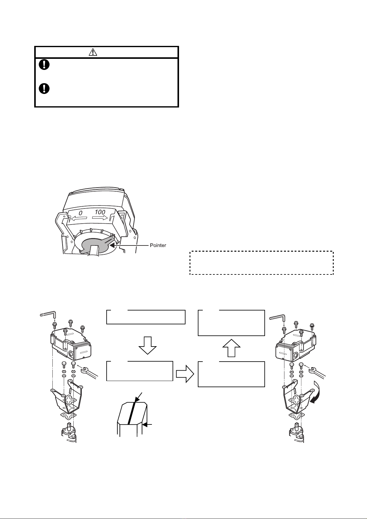
•Never rotate the joint out of “0” to “100”
range of the scale.
Before manually opening or closing the ACTIVAL, make
sure it is disconnected from the power supply.
As shown in Fig. 7, hold the joint with a tool such as a
hexagonal wrench, and turn the joint slowly toward the
position to set up.
Figure 7. Manual open/close operation
Auxiliary Switch / Auxiliary Potentiometer
(Optional)
CAUTION
•The auxiliary switch and the auxiliary poten-
tiometer are installed on site. (See Fig. 15.)
Refer to the instructions attached to them.
•Do not open the top cover except when ad-
justing the auxiliary switch or auxiliary poten-
tiometer.
•Do not put a load on the cover.
Wiring
CAUTION
•Disconnect power supply before performing
any wiring.
•This product is designed for 24 V AC power
supply voltage. Do not apply mains power.
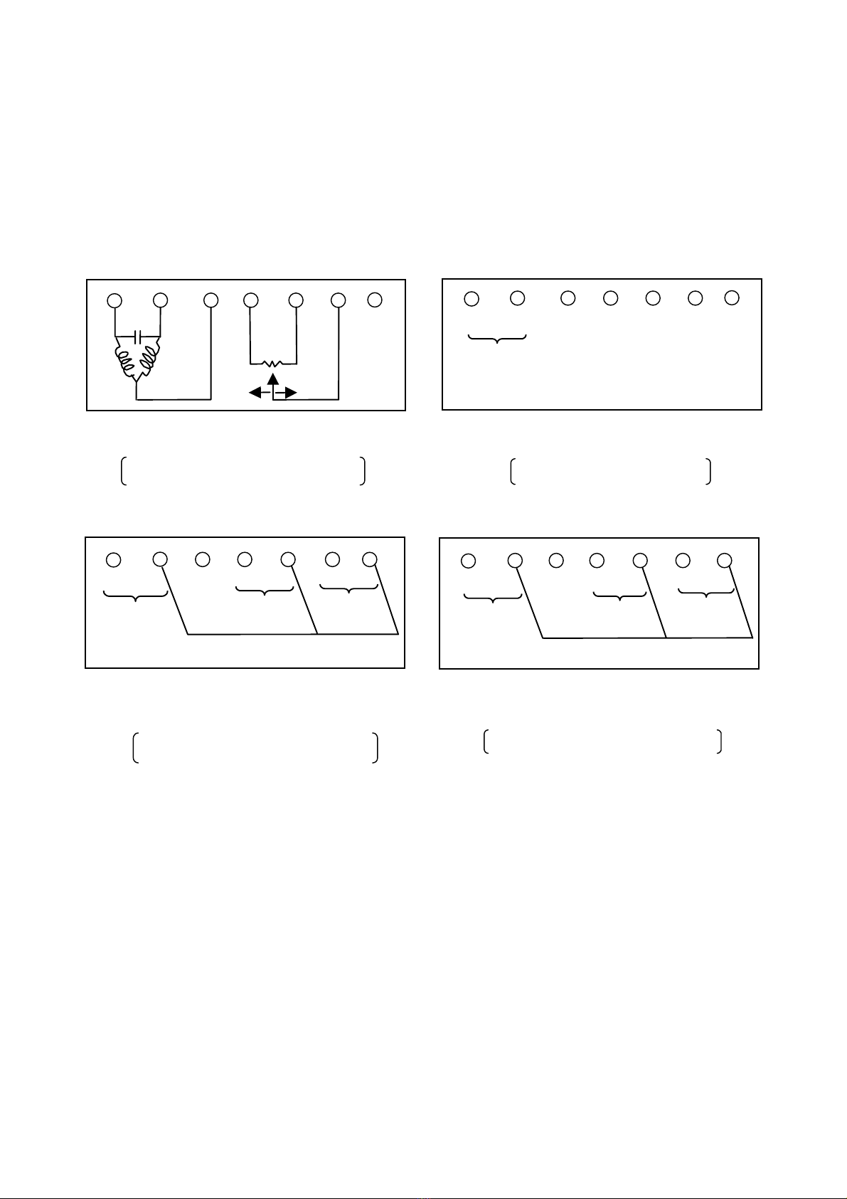
•For correct wiring of 4-20 mA DC input and
2-10 V DC input, refer to Figs. 12 to 14 and
make sure the polarity of power supply and
2-10 V DC output. Incorrect wiring may
result in PCB (printed circuit board) burnout.
•To prevent equipment damage, cover the
actuator except during wiring work.
Wiring precautions
1) Do not apply 24 V AC to the terminals 4, 5 and 6.
(Max. applicable voltage: 5 V DC)
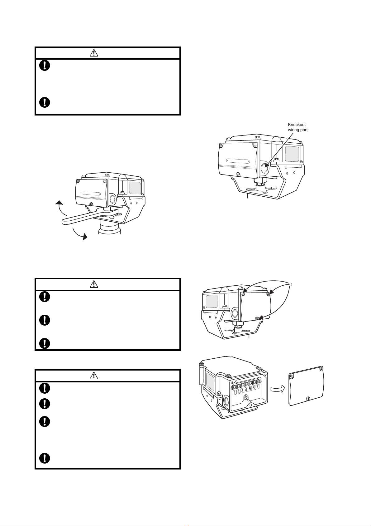
2) To lead the wires into the actuator, cut out a knockout
hole for a wiring port. There are two knockout holes
on the bilateral sides of the actuator terminal block:
one φ22 mm knockout hole on each side. Select a
knockout hole according to the conduit mounting
direction and cut it out by lightly knocking with a
screwdriver. (Refer to Fig. 8 )
Figure 8. Knockout hole for wiring port
3) Correctly connect the wiring to the terminals with M3.5
screws, referring to the wiring terminal diagrams
shown in Figs. 10 to 13 and the wiring examples
shown in Fig. 14 . (For the wiring of the auxiliary switch
or the auxiliary potentiomenter, refer to Fig. 15.)
4) When the ACTIVAL is used in a high-humidity
environment or outdoors, use a water-proof connector.
Figure 9. Terminal cover removal
Unscrew the three screws (M4 ×10) to remove the
terminal cover. (See Fig. 9.)
1. Remove
these screws
2. Remove terminal cover

10 AB-6464
For splash-proof enclosure...
1) Be sure to completely close the terminal cover and the top cover.
2) Waterproof the wiring port.
•For cable connection, use a water-proof connector.
Recommended product:
Seal conector ( Part No. 83104346-003 )
•For conduit connection, use a water-proof plica tube or the like to ensure water proofing.
Wiring Terminals
Model VY513XJ00XX
Figure 12. Wiring terminal diagram
Model VY513XJ00XX:
4-20 mA DC input with 2-10 V DC output type
Note: The terminals 2, 5 and 7 are connected inside of
the actuator. Figure 13. Wiring terminal diagram
Model VY514XJ00XX:
2-10 V DC input with 2-10 V DC output type
Note: The terminals 2 , 5 and 7 are connected inside of
the actuator.
Model VY511XJ00XX
Figure 10. Wiring terminal diagram
Model VY511XJ00XX:
Nominal 135 Ωfeedback potentiometer type
Figure 11. Wiring terminal diagram
Model VY512XJ00XX:
Nominal 135 Ωresistance input type
Open
(
O
)
Close
(
C
)
Open
(
O
)
Close
(
C
)
21 3 4 5 6
7
Vacant
Model VY514XJ00XX
T1~ T2⊥Vacant W B R
24 V AC
power supply
21 3 4 5 6
7
Vacant
T1~
2
1 3 4 5 6 7
T2⊥Vacant + -
2-10 V DC
output
24 V AC
power supply
4-20 mA DC
input
+ -
3 4 5 6 71 2
24 V AC
power supply
T1~ T2⊥Vacant + - + -
2-10 V DC
output
2-10 V DC
input
Model VY512XJ00XX

11 AB-6464
Wiring Connection Examples: Connection to Yamatake’s Controllers
Figure 14. Wiring connection examples
1
2
3
4
5
6
1
2
3
4
5
6
Transformer
Model VY511XJ
(Nominal 135 Ωfeedback
potentiometer)
Infilex GC
(Nominal 135 Ωfeed-
back
p
otentiometer
)
Power
supply
•
••
•Connection with Infilex
GC •
••
•Connection with Neostat
(Model TY900XZ)
1
2
4
5
6
W
Model VY512XJ (Nominal
135 Ωresistance input)
B
R
T1
T2
Neostat
Model TY900XZ
Transformer
Power
supply
W
B
R
•
••
•Connection with Model R35TC0/Model R36TC0
Power supply
Model R35TC0/
Model R36TC0
Model VY513XJ
(4-20 mA DC input
with 2-10 V DC output)
Transformer
13
14
1
4
5
2
+
-
+
-
T1
T2
6
7
Position indicator
+
-
+
-
Note: The terminals 2, 5, and 7 are connected
inside of the actuator.
•
••
•Connection with InfilexTM AC
Power supply
Infilex AC
Model VY514XJ
(2 -10 V DC input
with 2-10 V DC output)
Transformer
37
38
1
4
5
2
+
-
+
-
T1
T2
6
7
Position indicator
+
-
+
-
Note: The terminals 2, 5, and 7 are connected
inside of the actuator.

12 AB-6464
Wiring Connection of Auxiliary Switches / Auxiliary Potentiometer
Figure 15. Wiring connection of auxiliary switches/auxiliary potentiometer
•
••
•Connection of auxiliar
y
switches
OP1
OP2
OP3
OP4
OP5
OP6
P
a
r
t
N
o
.
83
1
6
17
9
2-
00
1
Terminal block
Auxiliary switch 1
(Adjustable between
0 % to 50 % positions)
Auxiliary switch 2
(Adjustable between
50 % to 100 % positions)
•
••
•Connection of auxiliar
y
potentiometer
NC
NO
Common
NC
Common
NO
OP1
OP2
OP3
Close
Open
Part No. 83161793-001
Terminal block
Auxiliary
potentiometer

13 AB-6464
Inspection and Maintenance
CAUTION
•Avoid touching the installed ACTIVAL (valve
body, yoke, joint). When being used to
control hot water, it reaches high tempera-
ture and may cause burn injury.
1) Inspection
Inspect the ACTIVAL according to Table 1.
Manually open/close the ACTIVAL at least once a
month if it is left in inactive state for a long period.
2) Maintenance
Visually inspect the fluid leakage of the valve and the
actuator operations every six months. If any of the
problems described in Table 2 are found, take
corresponding actions shown in the table.
Table 1. Inspection items and details
Inspection item Inspection interval Inspection detail
Visual inspection Semiannual •Fluid leakage from the gland and the flange face
•Loosened bolts
•Valve and actuator damages
Operating status Semiannual •Unstable open/close operation
•Abnormal noise and vibration
Routine inspection Any time •Fluid leakage to the outside
•Abnormal noise and vibration
•Unstable open/close operation
•Valve hunting
Table 2 Troubleshooting
(If an your problem is not solved by the corresponding action, please contact Yamatake near you.)
Problem Part to check Action
•Fluid leaks from the flange face. Loosened flange bolts
Gasket on the flange face
Misaligned piping
Tighten the flange bolts.
Replace the gasket.
Redo piping.
•Fluid leaks from the gland part. Loosened gland packing Tighten the gland nut.
•Fluid leaks from the bonnet. Loosened bolts Tighten the bolts.
•Valve does not operate smoothly /
valve stops halfway /
valve does not operate at all.
Conditions of the power applied and of the
input signal applied
Loosened terminals
Wiring condition / disconnected wires
Check the power supply and the controller
connected to.
Tighten the terminals.
Check the wiring.
•Fluid leaks to the outside of the
valve when the ACTIVAL is in fully
closed position.
Actuator pointer not pointing to fully closed
position
Fully close the ACTIVAL.
•The valve vibrates or produces an
abnormal noise.
Primary pressure condition
Differential pressure condition
Adjust the mounting position and installation
location.
•The auxiliary switch does not
operate.
Auxiliary switch (cam switch) condition
Loosened terminals
Wiring condition / disconnected wires
Redo the cam switch setting.
Tighten the terminals.
Check the wiring.
•The auxiliary potentiometer does
not operate.
Condition of resistance
Loosened terminals
Wiring condition / disconnected wires
Check the resistance value (1 kΩ).
Tighten the terminals.
Check the wiring.
•Valve hunting occurs. Secondary pressure condition
Differential pressure condition
Adjust the mounting position and installation
location.
Correct the control parameter setting of
controller.


Specifications are subject to change without notice.
Building Systems Company
http://www.yamatake.com
Rev. 2.0 Oct. 2005 AB-6464 0.5H-H (W00)
(J: AI-6464 Rev. 1.0) Printed in Japan.
Table of contents
Other Yamatake Control Unit manuals