Yamato BT43 User manual

BT43
MANUAL BACK-TACKING DEVICE
AZ7000SD-8, AZ8000SD-8, AZF8000G class
Thank you f or pur chasing BT 43.
For properly your BT43, please read over this manual and the manual for sewing machine
together to fully understand their contents.
After reading the instruction manual, please keep it in a location where it is easily acces-
sible to the operator.
Parts List
Instruction Manual

CONTENTS
1. Overview 1
2. Installation 2
2.1 Check and change of voltage 2
2.2 Control box Installation 3
2.3 Wiring diagram 4
2.4 Power cord connection 5
2.5 Precautions 5
2.6 Synchronizer installation 6
2.7 Automatic motor stop function 6
2.8 Automatic presser foot lifter device (special order parts) 7
3. Proper operation 10
3.1 Seam condition and device operation 10
3.2 Each section name and function of control panel 11
3.3 Adjustment at beginning of sewing 12
3.3.1 Tension releaser adjustment at beginning of sewing 12
3.3.2 Stitch plate tongue adjustment at beginning of sewing 12
3.4 Adjustment at end of sewing 13
3.4.1 Tension releaser adjustment at end of sewing 13
3.4.2 Stitch plate tongue adjustment at end of sewing 13
3.5 Mesh materials 14
3.6 Automatic motor stop function setting 14
3.7 Automatic presser foot lifter mechanism 15
4. Adjustments 16
4.1 Thread chain holding pressure 16
4.2 Knife change 16
4.3 Lower looper adjustment 17
4.4 Stitch plate tongue front-and-rear position 17
5. Troubleshooting 18

CONTENTS
Attention
The parts used for this product are subject to change without notice. If such a change is made, any part of the
contents and illustrations of this instruction manual may not conform to this product.
In preparing the instruction manual, we have made our best efforts for making it free of any error or omission.
If any error or omission should yet be found, it might not be rectified immediately.
Attention
◇This instruction manual is designed mainly for technicians, but it is advisable that also operators
read the instructions with mark to use the machine properly.
6. Test mode usage 19
6.1 Solenoid function test 19
6.2 Reset 19
6.3 Fabric sensor function test 19
**** I L L U S T R A T E D P A R T S L I S T ****

1
AZ-SD, AZF-G/BT43
1.Overview
Name:
Applied machine:
Features:
Notes:
Manual back-tacking device
2-needle machine for AZ7000SD-8 class, AZ8000SD-8 class and AZF8000G
class
◇
This BT43 device is applied to both stable seam condition on the material
and beautiful back-tacking of soft thread chain into the seam by using
the movable middle stitch plate tongue and tension releaser interlocked
with the electrooptical function for detecting the material.
◇
This BT43 device is applied to a short sewing distance by providing short
length of thread chain to be sewn into the seam.(as compared with our con-
ventional machines)
◇ThisBT43deviceisappliedtomeshmaterialsandpreventsmalfunctions
during operation.
◇
This BT43 device improves usability of the machine because of making the
length of the thread chain the same by stopping the motor automatically.
◇
With use of automatic presser foot lifter mechanism (special ordered),
this BT43 device also improves usability of the machine because of auto-
matically raising the presser foot after motor stop and lowering it at
the time of setting material.
◇Useapositionermotorfordetectingtheneedleposition.
◇
automatic motor stop function needs a motor that stops by external input
signal.
◇
Automatic presser foot lifter mechanism needs a motor that stops by
external input signal and outputs signal for the presser foot lifter.

2
AZ-SD, AZF-G/BT43
2.1 Check and change of voltage
Fig. 2-1
Table 2
Table 1
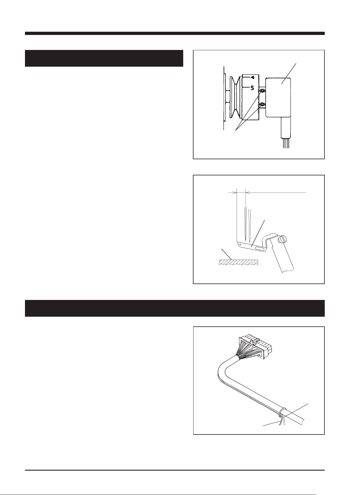
2.1.2 Changing of set voltage
2.1.1 Checking power supply voltage
2.Installation
power supply
voltage fuse capacity part number
of fuse
100 - 110 V 2 A 1070020
200 - 240 V 1 A 0010912
power
supply
voltage
voltage of
transformer
terminal
description
of voltage
indicate
plate
part number
of power
indicate
plate
100V 100V 100V 000805
200V 200V 200V 000806
220V 220V 220V 000742
240V 240V 240V 393120
If the power source voltage is different from
the set voltage of the control box, remove the
cover of the control box and change the position
of the tap on the transformer terminal to the
proper one. (See Table. 1) Change also the fuse
and the voltage panel to ones applicable to the
power supply voltage, referring to Tables 1 and
2.
Before operation, check that the power supply
voltage used is the same as the voltage printed
on the control box. (It is printed on the plate
on the rear of the control box.)
At shipment, the voltage printed on the control
box is 220 V and the usable range is 220 to 240 V.
If using this BT43 device at a voltage other
than this range, please contact our technician
in our agencies.
If you have your own technician of electronics,
take the following steps.
change the position
depending on voltage
Make this work before installing the control box to the
table.
If taking wrong steps, the control box can be damaged.
Be sure to follow proper steps.
ÃÁÕÔÉÏÎ
Before starting the work, pull the power
plug out of the control box and wait more
than 5 minutes.
ÃÁÕÔÉÏÎ

3
AZ-SD, AZF-G/BT43
2.2 Control box installation
Fig. 2-2
2.Installation
20 ㎜
70 ㎜
control box
280 ㎜
Install the control box under the table with the
wood screws referring to Fig.2-2.
operator

4
AZ-SD, AZF-G/BT43
2.3 Wiring diagram
2.Installation
Connect the connecting plugs referring to Fig.2-
3. Be sure to connect those plugs each other
with the same color and shape.
Connect the power plug to the control box.
tension releaser
solenoid
rotation
detector unit
fuse
intermediate
cable
4P white
rotation
detector unit
2P blue
tension releaser
solenoid
3P white
fabric detection
sensor
2P white
stitch plate
tongue solenoid
ground wire
to stitch plate
tongue solenoid
fabric
detection
sensor
To prevent the cord from hitting against a moving object
and thereby tearing, attach the cord securely to some
place like the table leg.
Be careful not to damage the cord.
ÃÁÕÔÉÏÎ
Fig. 2-3
Unplug the power cord from outlet before operating.
ÃÁÕÔÉÏÎ

5
AZ-SD, AZF-G/BT43
2.4 Power cord connection
2.Installation
2.5 Precautions
Fig. 2-4
blue
Table 3
Connect the brown and blue cords to the terminal
on the motor's side of the power switch.
The green/yellow cord is a ground wire. Connect
it to the same screw to which the ground wire of
the motor's side is connected as shown in Fig.2-4.
brown
green/
yellow
◇ Use always a fuse applicable to the capacity
of the power voltage used, referring to Table
3.
◇
Even if the glass tube for the fuse has the same
size as applicable one, its capacity may be
different. Be sure to check the printed capacity.
power supply
voltage fuse capacity part number
100 - 110 V 2 A 1070020
200 - 240 V 1 A 0010912
Using a fuse with inapplicable capacity can damage the
machine.
ÃÁÕÔÉÏÎ
Unplug the power cord from outlet before operating.
ÃÁÕÔÉÏÎ

6
AZ-SD, AZF-G/BT43
2.6 Synchronizer installation
2.Installation
Fig. 2-5
①
Fig. 2-6
2.7 Automatic motor stop function
Fig. 2-7
③
②
For a machine with this BT43 device, use always
a positioner motor.
(1) Set the motor to Position 1.
(2) Install the synchronizer ① to the machine
andtightenitlightlywiththescrews ② .
(3) Fasten the synchronizer ① to the machine
with the positioner pin.
(4) Turn the motor's power switch ON, run the
machine, and stop it after several stitches.
Then, the needle stops at the certain point.
(5) Loosen the screws ② and rotate the machine
pulley clockwise while taking care not to
movethesynchronizer ① .
(6) When the upper looper ③ is at the extreme
left,tightenthescrews ②securely.
(7)
Run the machine again and check that the machine
stops when the upper looper ③ is at the extreme
left.
at the extreme left
stitch plate
surface
Note: This function needs a motor that stops by
external input signal.
◇ Connect the black wire ④ (for GND) and the
whitewire ⑤(forsignal)oftheintermediate
cable to the tap for automatic motor stop, refer-
ring to Fig.2-7.
blackwire ④
whitewire ⑤
Refer to the instruction manual for the motor
used for details.
to“0V”,“GND”, or“circuit
ground”(The name differs
depending on the manufacturer.)
to“motor stop signal”
④
⑤

7
AZ-SD, AZF-G/BT43
2.Installation
2.8 Automatic presser foot lifter mechanism (special order parts)
Note: This mechanism needs a motor that stops by external input signal and outputs signal
for the presser foot lifter.
(1) Install the regulator and the solenoid valve on the proper position under the machine
table.
(2)
Settheaircylinder ①ontherearofthemachine.Insertthegrooveofthelifterholder
②tothelifterlever ③ .
2.8.1 Installing presser foot lifter mechanism
①
②
②③
③
②
①
③
②
③
Fig. 2-8 Fig. 2-9

8
AZ-SD, AZF-G/BT43
Fig. 2-10
2.8.2 Air piping
Refer to Fig. 2-10 to connect the air tubes. Cut the tubes properly for the connection.
Set the regulator at 0.2 to 0.4 MPa.
2.Installation
presser foot
lifter cylinder
4 × 2.5㎜
4 × 2.5㎜
solenoid vale
6 × 4㎜
to air source
regulator

9
AZ-SD, AZF-G/BT43
(1)Connectthe blackwire① (forGND)and the
white wire ② (for signal) of the intermediate
cable to the tap for automatic motor stop and
presser foot lifter.
blackwire ①
whitewire ②
Refer to the instruction manual for the motor
used for details.
(2)
Connect the solenoid valve cord to the connector
for the presser foot lifter of motor.
2.Installation
2.8.3 Wiring
to“0V”,“GND”, or“circuit
ground” (The name differs
depending on the manufacturer.)
to “motor stop signal” and
“presser foot lifter”
Note: Some manufacturers use the same connector for the input and output signals of
presser foot lifter.
Fig. 2-12
(Example) In case of Y motor
Connecttheblackwire ①andthewhitewire ②of
the intermediate cable to the pin with the number as
below. (Fig. 2-12)
Option A(white 12P)
blackwire ①
whitewire ②
Presser foot lifer(blue 3P)
whitewire ②
to pin No. 10 for“0V”
topinNo.4for“Upposition
stop input”
to pin No. 2 for “Presser
foot input”
2
10
4
②
①
Fig. 2-11
2
10
4
②
①

10
AZ-SD, AZF-G/BT43
3.Proper operation
Fig. 3-1
3.1 Seam condition and device operation
3.1.2 Device operation
3.1.1 Tension releaser operation
(1) Pull a thread chain backward and bring it to
the front.
(2) Pull a thread chain from the left to the
right along the cloth plate. Then, the
thread chain cutter cuts the thread chain
and holds the remaining portion. (At this
moment, preparation for back-tack sewing is
completed.)
(3) Sew a material.
(4) Raise the presser foot to pull a thread
chain backward.
(5) Bring the thread chain to the front.
Pull the thread chain from the left to the
right along the cloth plate.
Then, the thread chain cutter cuts the thread
chain and holds the remaining portion.
Repeat Steps (3) to (5).
To adjust the plain sewing seam condition, turn
thethreadtensionspringcaps ①to④inFig.3-
1.
To adjust the thread chain seam condition, turn
thethreadtensionspringcaps ⑤ ,⑥inFig.3-1.
Thread chain tension adjustment
(1) Turn the motor switch ON.
(2) Turn the control box switch ON.
(3) Sew a material and pull a formed thread
chain back.
Atthismoment,adjustthecaps ⑤and⑥so
that the thread chain forms a cord. (Under
this seam condition, the needle threads are
loose and the looper threads are tight.)
①②
③⑤⑥
④

11
AZ-SD, AZF-G/BT43
3.2 Each section name and function of control panel
Fig. 3-2
3.Proper operation
①“Lock”key
This is for making all the switches invalid to prevent wrong operation.
(When this key is pressed, all the lamps are lighted.)
②“▲”key
This is for increasing the set value.
③“▼”key
This is for decreasing the set value.
④“MODE”key
This is for changing the selected mode.
⑤“CLOCK”lamp
This is lighted by detection of the machine's rotation.
(This blinks two times for each rotation.)
⑥“START”lamp
This is lighted when the count at the beginning of sewing is adjusted.
⑦“END”lamp
This is lighted when the count at the end of sewing is adjusted.
⑧“TENSION”/“TONGUE”lamp
This shows the current setting mode by combination with other lamps.
⑨Display
This displays the set value.
①
②
⑤
③
④
⑥
⑦
⑧
⑨

12
AZ-SD, AZF-G/BT43
3.Proper operation
3.3 Adjustment at beginning of sewing
Fig. 3-3
Fig. 3-4
Fig. 3-5
lighted
lighted
3.3.2 Stitch plate tongue adjustment at beginning of sewing
3.3.1 Tension releaser adjustment at beginning of sewing
(1) Press the “MODE” key several times to ligh
the“START”and“TONGUE”lamps.
(2)
Adjustthecountbypressingthe“▲”and“▼”
keys so that the stitch plate tongue sticks
out when the sensor detects the material end
and the material reaches the needle holes.
(Two counts indicate one stitch.)
(1) Press the “MODE” key several times to light
the“START”lamp only.
(2)
Adjust the count by pressing the“▲” and
“▼”keyssothatthetensionreleaserchanges
the thread chain seam condition to the plain
sewing seam condition when the sensor detects
the material end and the material reaches
the needle holes. (Two counts indicate one
stitch.)
tongue sticks out

13
AZ-SD, AZF-G/BT43
3.4 Adjustment at end of sewing
Fig. 3-6
Fig. 3-7
Fig. 3-8
lighted
3.4.2 Stitch plate tongue adjustment at end of sewing
3.4.1 Tension releaser adjustment at end of sewing
(1) Press the “MODE” key several times to light
the“END”lamp only.
(2) Adjust the count by pressing the“▲” and
“▼” keys so that the tension releaser changes
the thread chain seam condition to the plain
sewing seam condition when the sensor detects
the material end and the material reaches
the needle holes. (Two counts indicate one
stitch.)
(1) Press the “MODE” key several times to light
the“END”and“TONGUE”lamps.
(2) Adjust the count by pressing the“▲” and
“▼”keyssothatthestitchplatetongueis
recessed when the sensor detects the mate-
rial end and the material reaches the needle
holes. (Two counts indicate one stitch.)
lighted
tongue is retracted
3.Proper operation

14
AZ-SD, AZF-G/BT43
3.Proper operation
3.5 Mesh materials
3.6 Automatic motor stop function setting
Fig. 3-9
lighted
If mesh materials are sewn and malfunctions of
the sensor occur, make the following adjustment.
(1) Turn the power OFF.
(2)Whilepressingthe“▲”and“▼”keysatthe
same time, turn the power ON.
(3) Press the “MODE” key several times to light
the“START”lamp only.
(4)Adjustthevaluewiththe“▲”and“▼”keys
so that the device detects the material end
correctly.
(5) Turn the power OFF.
When sewing normal materials other than mesh materi-
als, return the value to 0.
Fig. 3-10
lighted
By using the automatic motor stop function, the
count from material end detection of the sensor
to motor stop can be set.
(1) Turn the power OFF.
(2)Whilepressingthe“▲”and“▼”keysatthe
same time, turn the power ON.
(3) Press the “MODE” key several times to light
the“START”and“TENSION”lamps.
(4)Withthe“▲”and“▼”keys,adjustthecount
from sewing end to motor stop.
(Two counts indicate one stitch.)
(5) Turn the power OFF.
ÁÔÔÅÎÔÉÏÎ

15
AZ-SD, AZF-G/BT43
3.7 Automatic presser foot lifter mechanism
Fig. 3-11
The time can be set from material detection of
sensor to presser foot lowering. lighted
(1) Turn the power OFF.
(2)Whilepressingthe“▲”and“▼”keysatthe
same time, turn the power ON.
(3) Press the “MODE” key several times to light
the“START”,“END”, and“TENSION”lamps.
(4)Withthe“▲”and“▼”keys,adjustthetime
from material detection of the sensor to
presser foot lowering.
(5) Turn the power OFF.
3.Proper operation

16
AZ-SD, AZF-G/BT43
4.1 Thread chain holding pressure
4.2 Knife change
Fig. 4-1
Fig. 4-2
increase
decrease
③
kinfe
②
4.Adjustments
To adjust the thread chain holding pressure,
turnthenut ① .Whenthepressureistoolowor
too high, adjust the pressure.
● To increase the pressure, turn the nut ①
clockwise.
● To decrease the pressure, turn the nut ①
counterclockwise.
If the pressure is too high, a thread chain can
be cut before the thread chain presser holds it
or a material can be entangled.
If the pressure is too low, a thread chain comes
out of the thread chain holder too early and it
is impossible to sew the thread chain into a
seam beautifully.
(1)Turnthethreadchainpresserplate ②inthe
arrow direction with raising it slightly.
(See Fig.4-2)
(2)Loosenthescrew ③ .
If the knife does not move at this moment,
tapthepart ④lightlywithsomethinglikea
screwdriver.
(3) Change the knife. Regarding the direction
and position of a knife, see Fig.4-2.
(4)
Tighten the screw ③ securely and fasten a new
knife.
(5)
Fit the pin hole and the slot for the knife of
the thread chain presser plate ② on the pin and
the knife respectively and return the thread chain
presserplate ②totheoriginal
position.
alignment on
the left end
note the direction
of knife
Before adjusting, ALWAYS turn the motor switch OFF
and check that the motor has already stopped.
When removing the knife, be careful not to be cut hands
by the knife.
ÃÁÕÔÉÏÎ
④
①

17
AZ-SD, AZF-G/BT43
4.3 Lower looper adjustment
Fig. 4-3
④
③
⑤
②
①
4.4 Stitch plate tongue front-and-rear position
◇Frontposition
(1)Loosenthescrews ①andturnthesolenoid
cover ② in the arrow direction.(See Fig.
4-3)
(2)
When the stitch plate tongue is out, loosen
thescrew ⑥andmovethestitchplatetongue
arm ⑦ .
(3)
When the tongue is out from the stitch plate
by6mm,tightenthescrew ⑥securely.
Fig. 4-4
Fig. 4-5
⑧
apply
②
⑦
⑥
6 mm
To adjust the lower looper of a sewing machine
with a BT43 device, take the following steps.
(1) Loosen the screws ① and turn the solenoid
cover ②inthearrowdirection.
(2)Loosenthescrews ③andremovethesolenoid.
(3) Adjust the lower looper.
(4)
Insert the pin screw ④ into the hole of the
stitchplatetongue ⑤andreinstallthesolenoid.
(5)Tightenthescrews ③securely.
(6)Tightenthescrews ①securely.
◇Rearposition
(1) When the tongue is retracted, loosen the
screw ⑧ .
(2)
Apply the rubber cushion of the arm ⑦ to
thesolenoidcover ②sothatthetonguecan
be hidden under the stitch plate completely,
andtightenthescrew ⑧ .
stitch plate tongue is hidden
under stitch plate.
4.Adjustments
Always adjust the rear position of the stitch
plate tongue.
ÃÁÕÔÉÏÎ
Before adjusting, ALWAYS turn the motor switch OFF
and check that the motor has already stopped.
ÃÁÕÔÉÏÎ
This manual suits for next models
3
Table of contents
Popular Industrial Equipment manuals by other brands

CNC
CNC 3018-PRO user manual

MGF
MGF S80 SPREADER BEAM user guide

Spear & Jackson
Spear & Jackson BoilerMag XT Series Installation and servicing instructions

Vega
Vega HAN 8D Supplementary instructions

Graco
Graco PR-X Setup - Operation - Repair

Siemens
Siemens simovert EMC-Filter Compact PLUS operating instructions

Newport
Newport IDL165-LM Series user manual

ABB
ABB HT562742 Operation manual

Abbey Machinery
Abbey Machinery VF1500T Maintenance, Operating Instructions and Spare Parts Lists

ABB
ABB HT609588 Operation manual

TECO
TECO MOTOVARIO PBH Series Instructions for installation, use and maintenance

ABB
ABB HT566444 Operation manual