目次
Cautions in Using With Safety ..............................................................1
Explanation..................................................................................................................1
Table of Illustrated Symbols .........................................................................................2
Fundamental Matters of “WARNING!” and “CAUTION!” ...............................................3
Before Using this unit............................................................................4
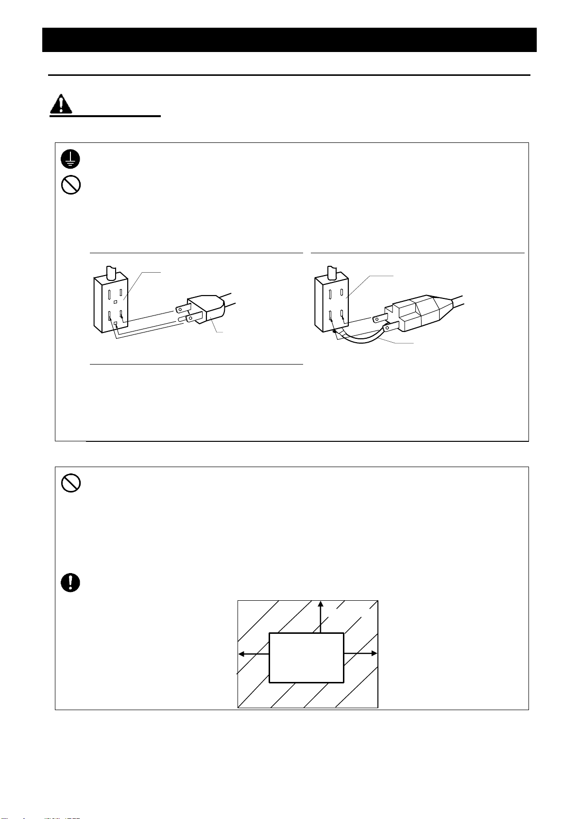
Requirements for Installation........................................................................................4
Requirements for Installation........................................................................................5
Requirements for Installation........................................................................................6
Component Names & Functions...........................................................7
Operation Method ..................................................................................8
Preparation for Operation.............................................................................................8
Operation.....................................................................................................................9
Timer Operation method ..............................................................................................9
Timer operation method.............................................................................................10
Handling Precautions ..........................................................................11
Maintenance Method............................................................................13
Daily Inspection and Maintenance..............................................................................13
When not using this unit for long term / When disposing............................................13
In the Event of Failure… ......................................................................14
Trouble Shooting........................................................................................................14
In such cases.............................................................................................................14
After Service and Warranty .................................................................15
Specification.........................................................................................16
Wiring Diagram ....................................................................................17
List of Dangerous Substances............................................................18