Yard Works 60-3815-0 User manual

24 V Cordless Tiller/Edger
60-3815-0
Owner's Manual
TOLL-FREE HELPLINE: 1 866 523-5218
Read all safety rules and operating instructions carefully before using this product.
WARNING

Technical Date
............................................................................................................................................................. 2
General Safety Rules.......................................................................................................................................................3
Specific Safety Rules...................................................................................................................................................... 4
Symbols........................................................................................................................................................................ 5
................................................................................................................................................................. 9/13
Operation ................................................................................................................................................................... 14/17
Maintenance ................................................................................................................................................................. 18
..................................................................................................................................................................... 8
21/22
Troubleshooting ............................................................................................................................................................. 19
Warranty..............
Parts list ...............
...............................................................
......................................................................................................................................................
.......................................................................................... 20
Replacement battery: YardWorks 24 V Battery (60-2152-2)
Assembly
Features
.......................................................................................................................................................... 7
Battery & Charger
TABLE OF CONTENTS
TECHNICAL DATA
2
Battery Type....................................................................................................................................... 24 V, 10 Ah Lead Acid
Charger Type....................................................................................................................................... 10 hour charging time
Cultivating Width.......................................................................................................................... 8 1/4 or 10" (21 or 25.4 cm)
Cultivating Depth................................................................................................................................................. 4" (10.2 cm)
Tilling Tine Diameter........................................................................................................................................... 8" (20.3 cm)
Edging Tine Diameter......................................................................................................................................... 8" (20.3 cm)
Edging Tine Depth................................................................................................................................................... 2" (5 cm)
Wheel Type......................................................................................................................... 7" (17.8 cm) Radial, Ball bearing
Weight with battery.........................................................................................................................................57 lbs (25.9 kg)
Weight without battery....................................................................................................................................41 lbs (18.6 kg)
Run time........................................................................................................................................ Approximately 25 minutes
CSA ........................................................................................................................................ .................................218549
#

GENERAL SAFETY RULES
WARNING:
READ AND UNDERSTAND ALL INSTRUCTIONS
Failure to follow all of the instructions listed below may
result in electric shock, fire, and/or serious personal injury.
READ THESE INSTRUCTIONS
3
Read the Owner’s Manual carefully. Become thoroughly
familiar with the controls and the proper use of the
equipment. Know how to stop the tiller and to disengage
controls quickly.
Do not operate a power tool in an explosive atmo-
sphere, such as in the presence of flammable liquids,
gases, or dust. Power tools create sparks that may ignite
the dust or fumes.
Ground Fault Circuit Interrupter (GFCI) protection should
be provided on the circuit(s) or outlet(s) that will be used
to charge the tiller. Outlets with built-in GFCI protection
are available, and may be used as an added safety
measure.
Do not expose power tools to rain or wet conditions.
Water entering a power tool increases the risk of electric
shock.
Do not allow children to operate this tool. Do not allow
adults to operate this tool without proper instruction.
Always wear safety glasses equipped with side shields.
Everyday glasses only have impact resistant lenses.
They are NOT safety glasses. Following this rule will
reduce the risk of an eye injury.
Wear long pants made from a heavy material, boots, and
gloves. Avoid loose garments or jewellery that can get
caught in moving parts.
Do not operate this tool while barefoot or wearing
sandals or similar lightweight footwear. Wear protective
footwear that will keep the feet safe and improve footing
on slippery surfaces.
Secure long hair so that it is above shoulder level, in
order to prevent it from getting caught in moving parts.
Do not operate the tiller while under the influence of
alcohol or drugs.
Do not put hands or feet near or under the tines.
Exercise caution in order to avoid slipping or falling.
Avoid accidental starting. Verify that the switch trigger is
not engaged before plugging in the tool.
Never pick up or carry the tiller while the tines are turning
or while the motor is running.
Keep the tool in good working condition.
Frequently check all nuts, bolts, and screws for proper
tightness in order to ensure that the tool is in safe work-
ing condition.
Keep the tiller free of grass, leaves, or grease, in order to
reduce the risk of a fire.
Do not use the tool if the switch does not turn it on or off.
Any tool that cannot be controlled using the switch is
dangerous, and must be repaired.
Disconnect the battery from the tool before making any
adjustments, changing accessories, or storing the tool.
Following these preventive safety measures reduces the
risk of starting the tool accidentally.
Unplug the tiller and verify that all moving parts have
come to a complete stop before cleaning, repairing, or
inspecting the tool.
Never spray water directly into the motor compartment.
Service on the tiller must be performed by qualified repair
personnel only. Service or maintenance that is performed
by unqualified personnel could result in injury to the user
or damage to the product.
Use only identical replacement parts when servicing the
tiller. The use of unauthorized parts may create a risk of
serious injury to the user, and may cause damage to the
product.

SPECIFIC SAFETY RULES
WARNING:
4
When starting the tiller, follow the instructions carefully,
take up a normal operating position, and keep all body
parts well away from the tines.
If the tiller strikes a foreign object, stop the motor,
thoroughly inspect the tool for any damage, and repair any
damage before restarting and operating the tool.
Never leave the operating position while the motor is
running.
Unplug the tool before unclogging the tines and before
making any repairs, adjustments, or inspections.
Do not overload the capacity of the tiller by cultivating too
deep in a single pass or at too fast a speed.
Be aware that the equipment may unexpectedly bounce
upward or jump forward if the tines strike buried obstacles
such as large stones, roots, or stumps.
Never operate the tool on a slope.
Use extreme caution when pulling the tiller toward you.
Save these instructions. Refer to them frequently, and use
them to instruct others in the proper use of this tiller.
Dust created by power sanding, sawing, grinding, drilling, and other construction activities may contain chemicals that
are known to cause cancer, birth defects, or other reproductive abnormalities. Some examples of these chemicals
include:
• lead from lead-based paints,
• crystalline silica from bricks, cement, and other masonry products, and
• arsenic and chromium from chemically-treated lumber.
The risk of exposure to these chemicals varies according to how often you do this type of work. In order o reduce your
exposure to these chemicals, work in a well ventilated area, and use approved safety equipment, such as dust masks
that are specially designed to filter out microscopic particles.

5
SYMBOLS
Keep Bystanders Away
Cutting Hazard
Eye Protection
To reduce the risk of injury, the user must read and
understand the Owner’s Manual before using this product.
Keep all bystanders at least 50' (15 m) away.
Keep feet and hands away from rotating tines.
50
'
15
m
Some of the following symbols may appear on this tool. Study them carefully and learn their meaning. Proper
interpretation of these symbols will allow for better and safer operation of the tool.
Read the Owner’s Manual
Safety Alert
SYMBOL NAME DESIGNATION/EXPLANATION
Voltage
Current
Frequency (cycles per second)
Power
Time
Type of current
Type of current
Rotational speed, at no load
Double-insulated construction
Revolutions, strokes, surface speed, orbits, etc., per minute
Do not expose to rain or use in damp locations.
Always wear safety goggles, safety glasses with side shields, or
a full face shield when operating this product.
Precautions that involve your safety.
Wet Conditions Alert
.../min Per Minute
Class II Construction
n
o
No Load Speed
Direct Current
Alternating Current
min Minutes
W Watts
Hz Hertz
A Amperes
V Volts
Hot Surface To reduce the risk of injury or damage, avoid contact with any
hot surface.

6
SYMBOLS
SERVICE
Servicing must be carried out with extreme care and
knowledge, and should only be performed by a qualified
service technician. For service or repairs, call the
TOLL-FREE HELPLINE: 1 866 523-5218. When servicing,
use only identical replacement parts.
WARNING:
Keep this Owner's Manual for future reference
The following signal words and meanings are intended to explain the levels of risk associated with this product.
SYMBOL SIGNAL MEANING
DANGER: Indicates an imminently hazardous situation that can result in death or
serious injury if it is not avoided.
WARNING: Indicates a potentially hazardous situation that may result in death or
serious injury if it is not avoided.
CAUTION: Indicates a potentially hazardous situation that may result in minor or
moderate injury if it is not avoided.
CAUTION: (Without Safety Alert Symbol) Indicates a situation that may result in property damage.
WARNING:
In order to avoid serious personal injury, do not attempt
to use this product until you have thoroughly read and
completely understood the Owner's Manual. Save this
Owner's Manual, and review it frequently in order to
ensure continued safe operation, and use it to instruct
others with respect to the proper use of this product.
The operation of any power tool can result in foreign objects being thrown into the eyes, which can
result in severe eye damage. When using this power tool, always wear safety goggles, safety glasses
with side shields, or a full face shield, if necessary. A Wide Vision Safety Mask is recommended for
use over eyeglasses or standard safety glasses with side shields. Always use eye protection that
complies with ANSI Z87.1.

BATTERY & CHARGER
The battery that is supplied with the tiller is a maintenance-
free, sealed, 24 V storage battery. It can be tipped without
danger of acid spillage. The charger will require
approximately 10 hours to recharge a fully discharged
battery.
Allow at least 10 hours of battery charging before using
the tiller for the first time.
For optimal performance, charge the battery every two
weeks, even when it is not in use.
Charge the battery in a cool, dry place.
The battery does not have to be fully discharged before
recharging. This battery will not develop a memory.
2 to 3 initial charging/discharging cycles may be required
in order to reach the maximum run time/capacity.
When it is fully charged, the battery can be stored in
temperatures as low as 23 °F (–5 °C) for a period of up
to two weeks before it requires recharging.
Operate the battery charger in temperatures between 23°
and 104° F (–5° and 40° C).
Use only the charger that is provided by the manufacturer
to charge the battery.
DO NOT ABUSE THE CHARGER CORD. Do not carry
the charger by the cord. Do not disconnect the charger
from the outlet or the tiller by pulling the charger cord.
Do not the service the tiller with the charger connected
or with the safety key installed.
Do not operate a damaged charger. Replace the charger
cord or the charger immediately .
Charge the tiller battery in a dry location Do not expose
the tiller or the charger to rain. Do not charge the battery
in wet locations.
Keep the tiller and the charger away from water, heat
sources (radiators, heaters, stoves, etc), flames, and
chemicals.
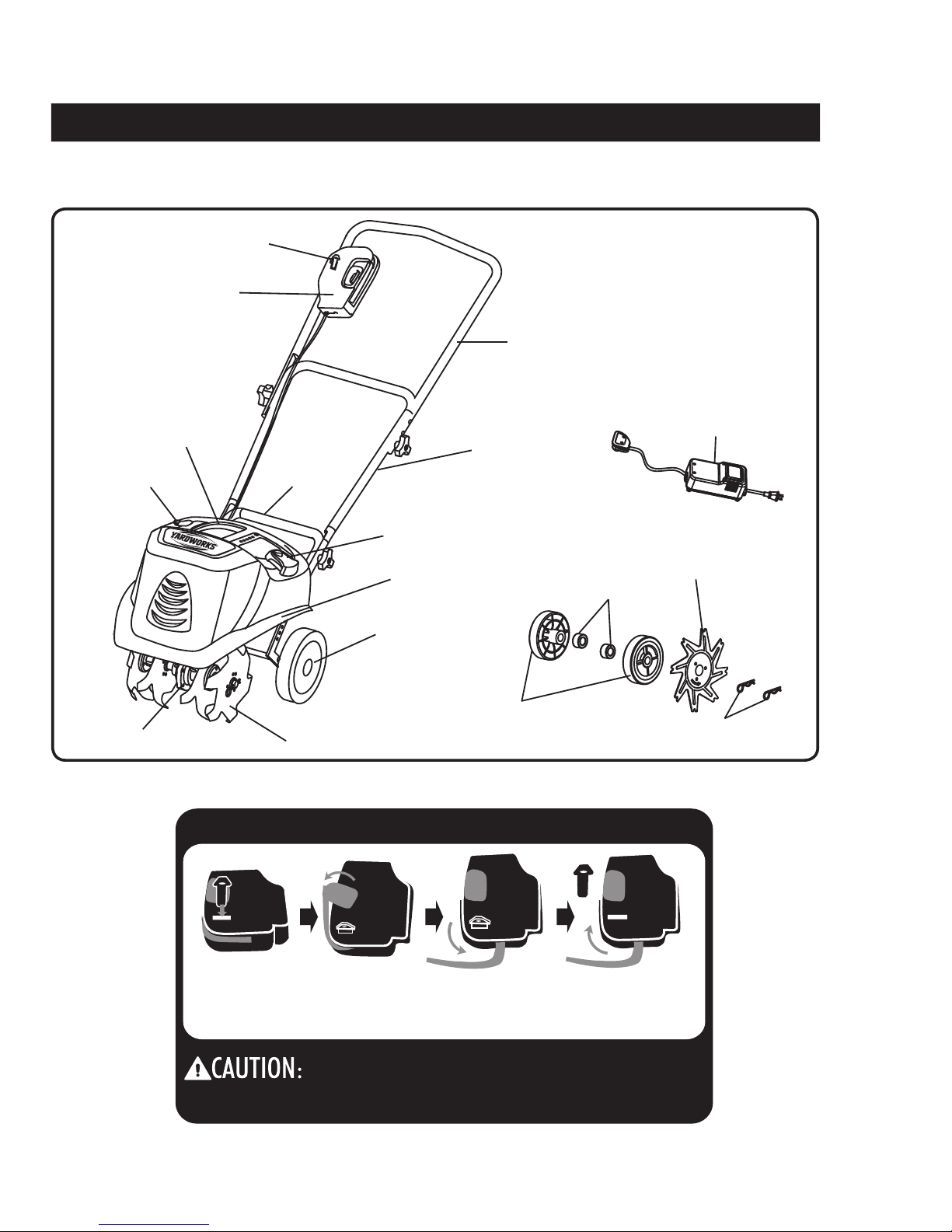
Disconnect the battery from the battery clip attachment.
The battery can be charged in or out of the tiller/edger.
Plug the charger connector into the jack on the
tiller/edger battery.
Connect the transformer to the charger.
Plug the transformer into a polarized household outlet.
The charging light and the power light will light up.
When the battery is fully charged, the charging light will
change from red to green.
For optimum performance, it is recommended that the
tiller be charged every two weeks when it is not in use.
Cold weather can shorten the battery life if the battery
is not charged every 2 weeks during the winter season.
It is recommended that the battery be removed from the
tiller and stored in a dry location, at temperatures
between 40° and 75° F (5° and 25° C).
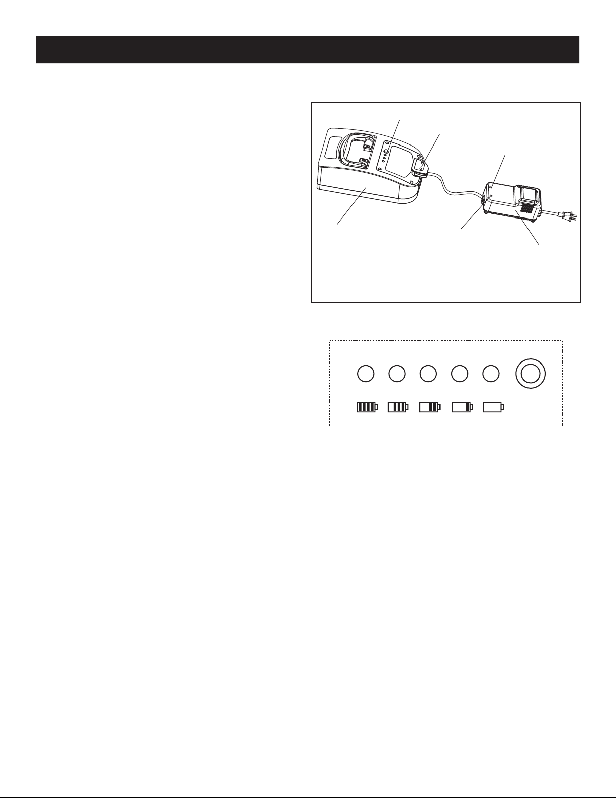
CHARGING PROCEDURE (Fig.1)
Fig. 1
Battery
BCI Switch
Charger connector
LED Charging light
Note: The left side is the Power
indicator. The right side is the
Charging (RED), and Fully
Charged (GREEN) indicator.
LED Power light
Charger
Fig. 2
BATTERY CAPACITY INDICATORS: (Fig. 2)
Push the Battery Capacity Indicator (BCI) switch, which is
located on the top of the battery. The lights will indicate the
battery's capacity, according the following list.
If three GREEN lights are lit, this indicates that the
battery is charged to full capacity.
If two GREEN lights are lit, this indicates that the
battery is charged to 80% of its capacity.
If only one GREEN light is lit, this indicates that the
battery is charged to 60% of its capacity.
If the AMBER light is lit, this indicates that the battery
is charged to 40% of its capacity, and will soon require
charging. It is recommended that the battery be charged
at this point.
If the RED light is lit, this indicates that the battery is
charged to 20% of its capacity, and that it requires
immediate charging before it can be used.
7
Green Green Green Amber Red BCI switch

8
FE ATURES
Fig. 3
DIAGRAM OF THE TILLER
See Figure 3.
POWER SWITCH TRIGGER The power switch trigger starts and stops the rotation of the tines.
SWITCH OPERATION
1. Insert the
safety key.
Do not attempt to override the operation
of the safety key or lever.
Power switch
assembly
TINE SHIELD
7" (17.8 cm) RADIAL TIRES
FIXED KNOB
BATTERY CLIP
Safety key
Blade
Gear box
Upper handle
Middle handle
Lower handle
Charger
2 Eging wheels
2 tubes
Edging blade
2 hitch pins
2. Push the safety tab out
in order to expose the
lever.
3. Pull the lever up
in order to start
the tiller.
4. To stop the tiller , release
the lever, and then remove
the safety key.
10 Ah 24 V battery

9
UNPACKING
This product requires assembly.
Carefully remove the tool and any accessories from
the box. Verify that all of the items that are listed in
the packing list are included.
Inspect the tool carefully in order to verify that no
breakage or damage occurred during shipping.
Do not discard the packing material until the tool has
been carefully inspected and satisfactorily operated.
If any parts are damaged or missing,
call 1 866 523-5218 for assistance.
PACKING LIST
Tiller
Battery (pre-installed)
Battery clip
Battery clip
Charger
Wheel pull pin(2)
Tine Hitch pins (2)
Cultivating Tines (4)
Edging wheel (2)
Edging Tine(1)
Wing nuts (4)
Bolts (4)
ASSEMBLY
WARNING:
If any parts are missing, do not operate this tool
until the missing parts have been replaced. Failure
to heed this warning could result in serious
personal injury.
WARNING:
Do not attempt to modify this tool or to create
accessories that are not recommended for use
with this tool. Any such alteration or modification
constitutes misuse, and could result in a hazardous
condition that may lead to serious personal injury.
WARNING:
Do not connect the Battey to the power supply
until assembly is complete. Failure to comply could
result in accidental starting, and possible serious
personal injury
Lower Handle
Fig. 4
Upple handle
Middle handle
Wing nuts
and bolts
Battery charger
Battery
Battery clip
Cultivating Tines (4)
Bolts (4)
Tine hitch pins (2)
Wing nuts (4)
Wheel pull pin (2)
Edging wheel (2)
Edging Tine (1)

10
POSITIONING THE HANDLEBAR
See Figure 5.
1. Align the holes on the middle handle with the holes on the lower handle. Insert the bolts, and tighten them
using the wing nuts provided.
2. Align the holes on the upper handle with the holes on the middle handle. Insert the bolts, and tighten
3. Assembling the Battery clip. Insert the battery clip between battery and plastic enclosure.
them using the wing nuts provided.
NOTE: The upper handle can be set at 3 different height levels for increased user comfort.
ASSEMBLY
Fig. 5
Lower Handle
Upple handle
Middle handle
Wing nuts
and bolts
Battery clip
Safety Key

11
ASSEMBLY
NOTE: When they are installed correctly, the flute on the tines should line-up, and the angled edge of the tine blades
should point toward the ground (Fig. 7).
NOTE: The tiller will not operate properly if the tines are not installed correctly. If there is a problem with the cultivating
operation of the tiller, check the tines for proper positioning.
Note: The directional arrow that is displayed on each tine should point toward the front.
3. Place tine (3) onto the shaft. The flute of tine (3)
should face away from the gear box. (Fig. 6.3)
4. Place tine (4) onto the shaft. The flute of tine (4)
should face in toward tine (3). Insert the hitch pin into the
holes in order to secure the tines to the tine shaft. (Fig. 6.4)
Fig. 6.3
FLUTE
GEAR BOX
3
2
13
FRONT
Fig. 6.4
3
2
1
4
4
FRONT
INSTALLING THE TINES
See Figure 6.1-6.4
The tiller comes with four tines. In order for the tiller to work properly, the tines must be installed in the correct order.
The tiller can be used with four tines or two tines.
Disconnect the battery from the tiller.
Lean the unit back on its wheels so that the handlebar rests on the ground.
1. Place tine (2) onto the shaft. The flute of tine (2)
should face away from the gear box. (Fig. 6.1)
Fig. 6.1
FLUTE
GEAR BOX
TINE SHAFT
FRONT
2
2
2. Place tine (1) onto the shaft. The flute of tine (1)
should face in toward tine (2). Insert the hitch pin into the
holes in order to secure the tines to the tine shaft. (Fig. 6.2)
FRONT
Fig. 6.2
1
2
1

12
ASSEMBLY
Fig.
Fig. 8
7
See Fig. 7.
TINES INSTALLED CORRECTLY
1 32 4
FLUTE FLUTE
GEAR BOX
FRONT
TINES INSTALLED CORRECTLY
Place tine (1) onto the shaft, and place tine (4) onto the shaft on the other side. Insert the hitch pin into the holes in
order to secure the tines to the tine shaft. (Fig. 8)
INSTALLING TWO TINES FOR TILLING A NARROW AREA
1
4
4
FLUTE HITCH PIN
FRONT

13
ASSEMBLY
See Figure 9.1-9.2
1. Place the left edging wheel (2) onto the shaft, and then place the edging blade (3) onto the shaft, with the flute of
the blade facing in toward the gear box. Insert the hitch pin into the holes in order to secure the blade to the shaft.
2. Place the right edging wheel (1) onto the shaft. Insert the hitch pin into the holes in order to secure the wheel to
the shaft.
Fig. 9.2
Fig. 9.1
GEAR BOX
SHAFT
23
1
T
N
O
R
F
FLUTE
GEAR BOX
SHAFT
HITCH
PIN HITCH
PIN
23
1
FRONT
FLUTE
INSTALLING THE EDGING BLADE

OPERATION
14
Note: For optimum performance, it is recommended that the tiller be charged every two weeks when it is not in use.
Cold weather can shorten the battery life if the battery is not charged every 2 weeks during the winter season. It is
recommended that the battery be removed from the tiller and stored in a dry location, at temperatures between 5°
and 25° C (40° and 75° F).
CHARGING PROCEDURE
BATTERY CAPACITY INDICATORS:
Push the Battery Capacity Indicator (BCI) switch, which is located on the top of the battery. The lights will indicate the
battery's capacity, according the following chart.
USE ONLY A YARDWORKS REPLACEMENT BATTERY (60-2152-2).
Battery
BCI Switch
Charger connector
LED Charging light
Note: The left side is the Power indicator.
The right side is the Charging (RED),
and Fully Charged (GREEN) indicator.
LED Power light
Charger
1. Remove the safety key from the switch on the tiller.
2. Disconnect the battery from the motor clip attachment.
3. The battery can be charged in or out of the tiller.
4. Plug the charger connector into the jack on the tiller
battery.
5. Plug the charger into a polarized household outlet.
The charging light and the power light will light up.
When the battery is fully charged, the charging light
will change from red to green.
Green Green Green Amber Red BCI switch
LIGHTS
3 green lights
2 green lights
1 green lights
Amber light
Red light
INDICATS
The battery is at full capacity
The battery is at 80% capacity
The battery is at 60% capacity
The battery is at 40% capacity,
and requires charging soon
The battery is at 20% capacity,
and requires charging
immediately
Note: When the charger is unplugged from the outlet,
the charger connector must also be unplugged from the
battery, or else the battery will discharge itself through
the charger.

STARTING THE MOWER
SAFETY KEY:
TO START THE MOWER:
1. Insert the
safety key. 2. Push the safety tab out
in order to expose the
lever.
3. Pull the lever up
in order to start
the tiller.
4. To stop the tiller, release
the lever, and then remove
the safety key.
Carefully follow the illustration below, in order, when starting the tiller.
Safety key Safety key
Storage Operating
In order to prevent accidental start-up or unauthorized use of the
battery-operated tiller, a removable safety key has been
incorporated into the design of the tiller. The tiller is
completely disabled when the safety key is removed from the
tiller
NOTE: THE SAFETY KEY HAS A HOLE THROUGH THE
CENTRE THAT ALLOWS FOR STORAGE ON A HOOK,
OUT OF THE REACH OF CHILDREN.
CAUTION: ALWAYS REMOVE THE SAFETY KEY FROM THE TILLER WHEN THE TILLER IS LEFT UNATTENDED.
OPERATION
15
CAUTION: Do not attempt to override the operation of the safety key or lever.
WARNING: The operation of any tiller can result in foreign objects being thrown into the eyes, which can
cause severe eye damage. Always wear safety glasses while operating the tiller and while performing any
adjustments or repairs.
WARNING: Ensure that other people and pets remain at least 100' (30 m) away when the tiller is in use.
INSPECT THE CUTTING AREA
Remove all stones, sticks, wire, bones, and other debris that might be thrown by the rotating blades.
CIRCUIT BREAKER: If the motor of the battery-powered tiller is overloaded for an extended period of time, it may
become hot. If this happens, the circuit breaker will switch the motor off in order to protect it from overheating. The
tiller can be restarted after waiting approximately 5-10 minutes.

16
The tiller can be used to break up garden soil and to prepare
a seed bed for planting. Plan ahead in order to leave enough
room between the seed rows to allow for cultivating after the
plants have grown.
Roll the tiller to the work area.
For general cultivating, remove or adjust the wheel
assembly, using the guidelines found in the section
entitled “Adjusting the Wheel Position" on page 18.
The wheel assembly has two installation positions. Based on
the type of soil that is being cultivated and the soil conditions
at the time, the proper height of the wheel assembly will vary.
Adjust the positioning of the drag bar using the guidelines
found in the section entitled “Adjusting the wheel assembly
and the Wheel Position" on page 18.
Verify that the work area is clean and free of obstructions.
Stand behind the tiller, with the tines on the ground.
Pull the switch trigger toward the handlebar in order to
begin tine rotation.
NOTE: If the machine moves forward too quickly, and the
wheel assembly is installed, push down on the handlebar in
order to allow the wheel assembly to penetrate the soil, which
will slow the forward motion of the tiller. The rotating
tines help to pull the tiller forward, so use a slower speed
and a shallow depth setting when learning to use the tiller,
and when cultivating rough or uneven ground.
NOTE: It may take several passes over the same path in
order to reach the desired depth. Do not try to dig too
deeply in the first pass. If the tiller jumps or bucks, allow
it to move forward at a slightly faster pace, or install the
wheel assembly.
In order to dig more deeply, lift up on the handlebar. Apply
downward pressure on the handlebar for more shallow
cultivating.
If the tiller stays and digs in one spot, try rocking it from
side to side in order to start it moving forward again.
If the soil is very hard, water it a few days before
cultivating.
Avoid working the soil when it is soggy or wet. Wait a day
or two after a heavy rain for the ground to dry.
OPERA
WARNING:
Do not allow familiarity with power tools to make you
careless. Remember that a fraction of a second of
carelessness is enough to cause a serious injury.
WARNING:
Always wear safety goggles or safety glasses with side
shields when operating tools. Failure to do so could
result in objects being thrown into the eyes, which could
cause a serious injury.
WARNING:
Do not use attachments or accessories that are not
recommended by the manufacturer of this tool. The use
of attachments or accessories that are not
recommended can result in serious personal injury.
WARNING:
Keep hands, feet, and all other parts of the body or
clothing away from the rotating tines and all other
moving parts. The tines begin to rotate forward when
the switch trigger is depressed, and they continue to
rotate until the switch trigger is released. Any contact
could result in serious personal injury.
PREPARING THE SEED BED
TION

17
OPERATION
EDGING FEATURE
See Figure 11.
This tiller is equipped with an edging feature.
Remove the tines.
Install the edging wheels and the edging blade.
(See Figure 9.1-9.2)
Fig. 11
Fig. 10
GENERAL CULTIVATING
See Figure 10.
Shallow cultivating (less than 2" (5 cm) deep) can be used
to disrupt weeds and aerate the soil without injuring nearby
plant roots. It should be done often so that weeds do not
grow large and get tangled in the tines of the tiller.
The two outer tine blades can be removed from the unit in
order to allow for a more narrow cultivating width. Follow
these steps to remove the two outer tines:
Disconnect the battery from the tiller; remove the hitch pins
from the holes on the ends of the tine shaft; remove the
outside tine blades and felt washers from the tine shaft;
and insert the hitch pins into the holes that were uncovered
when the felt washers were removed.
NOTE: The tiller will not operate properly if the tines are
not installed correctly. If there is a problem with the
cultivating operation of the tiller, check the tines for proper
positioning.

18
ADJUSTMENTS
In order to prevent accidental starting, which could
cause serious personal injury, disconnect the battery
from the tiller before making any adjustments.
ADJUSTING THE WHEEL ASSEMBLY
WARNING:
See Figure 12.
The drag bar can be used to help control the speed of the
tiller and the depth of cultivation. It is assembled with the
wheel assembly, and is secured to the tiller using a locking
pin.
To adjust the height of the drag bar:
1. Disconnect the battery from the tiller.
2. Remove the locking pins (1).
3. Shift the wheel assembly (2) up or down, depending on the
desired depth.
4. Reinsert the locking pins through the support rod (3) and
the wheel assembly in order to secure it.
Fig.12
WHEEL ASSEMBLY(2)
SUPPORT
ROD(3)
LOCKING
PIN(1)
Follow these steps in order to prepare the tool storage.
• Verify that the safety key is removed and stored in a safe place.
• Clean the tool .
• Store the tool in a clean, dry location. Do not store it next to corrosive materials, such as fertilizer or rock salt.
• Store the tool indoors, in a cool, dry place, out of the reach of children.
sheet. Plastic coverings trap moisture around the mower,
• The battery should be charged every two weeks, even when it is not in use. If the battery is completely discharged after an
extended storage period without being recharged, it will achieve full efficiency again after several charging cycles.
• The battery contains lead cells. After their lifetime has expired, they cannot be disposed of in the same manner as normal
household trash, but must be disposed of properly.
• The handle can be folded away completely for storage. Be sure not to bend or kink the power
• Dispose of batteries according to local by-laws because this Lead-acid batteries contain lead and sulphuric acid that are
hazardous materials.
cord.
STORAGE
• Do not cover the tool with a solid plastic
which causes rust and corrosion.
POSITION

19
MAINTENANCE
WARNING:
Use only identical replacement parts when servicing the
tiller. The use of any other parts may create a hazard or
cause damage to the product.
WARNING:
Always wear safety goggles or safety glasses with side
shields when operating a power tool or when performing
an operation that creates dust. If the operation is dusty,
wear a dust mask.
WARNING:
Disconnect the battery from the tiller and wait for all
moving parts to come to a complete stop before
inspecting, cleaning, or servicing the tiller.Failure to
follow these instructions could result in serious personal
injury or property damage.
GENERAL MAINTENANCE
Avoid using solvents when cleaning plastic parts. Most
plastics are susceptible to damage from various types of
commercial solvents. Use a clean cloth to remove dirt,
dust, oil, grease, etc.
WARNING:
Do not let brake fluid, gasoline, petroleum based products,
penetrating oils, etc., come into contact with plastic parts.
These chemicals can damage, weaken, or destroy plastic,
which may result in serious personal injury.
Only the parts that are shown on the parts list are intended
to be repaired or replaced by the user. All other parts
should be replaced at an Authorized Service Center
Maintenance Tips:
Before using the tiller/edger, inspect the condition of the
tines. If the ends come to a sharp point, they may be worn
and should be replaced. Inspect all moving parts and
tighten any loose bolts before using. When storing the
tiller/edger for long periods of time, apply machine oil to the
tines and shaft to help prevent rust.
NOTE: It is recommended that the battery be recharged every
two weeks, even when it is not in use. This battery will not
develop a memory.
Tilling/Cultivating Tips:
· When is it best to till or cultivate?
It is best to till or cultivate in the fall. Soil moisture and
temperature conditions are more favorable for
decomposition of organic matter, which will help to prevent
weeds from growing in the spring.
· How do I know if the soil is ready to be tilled or cultivated?
Test the moisture of the soil by squeezing a handful of
soil into a tight ball. If the ball remains tight after you
release your grip, the soil is too moist. If the ball
crumbles, the soil is ready to be tilled or cultivated.
Edging Tips:
Edging can make a lawn look finely groomed along the
borders, and can prevent "creeping" grasses from growing
outside of their boundaries. It is recommended that edging
be performed once per month, in order to help minimize
overgrowth next to walkways, gardens, patios, and
driveways.
TROUBLESHOOTING
PROBLEM CAUSE SOLUTION
The tiller does not start. The battery is not charged.
The internal thermal circuit breaker
has been tripped.
The motor/tine control switch is
defective.
Charge the battery.
Disconnect the battery from the tiller.
Allow the tiller to cool down for 30 to 45
minutes. The motor will reset
automatically.
Replace the motor/tine control switch.
The motor runs, but the tines
do not rotate.
The gear train is not working properly. Call 1 866 523-5218

20
WARRANTY
For TWO YEARS from the date of purchase within Canada, YARDWORKS CANADA will, at its option, repair or replace
for the original purchaser, free or charge, any part or parts found to be defective in material or workmanship.
This warranty does not cover:
1. Any part which has become inoperative due to misuse, commercial use, abuse, neglect, accident, improper
maintenance or alteration; or
2. The unit, if it has not been operated and/or maintained in accordance with the owner's manual;or
3.Normal wear, except as noted below;
4.Routine maintenance items such as lubricants, blade sharpening;
5.Normal deterioration of the exterior finish due to use or exp
6.Battery carries a one (1) year warranty against defects in workmanship and materials.
osure.
Full One Hundred Twenty Days Warranty on Normal Wear Parts: Normal wear parts are defined as blade adaptors,
blades, grass bags and tires. These parts are warranted to the original purchaser to be free from defects in material and
workmanship for a period of one hundred twenty (120) days from the date of retail purchase.
How to Obtain Service: Warranty service is available, with proof of purchase, through your local authorized service
dealer or distributor. If you do not know the dealer or distributor in your area, please call toll free 1 866 523-5218. The
factory will not accept the return of a complete unit unless prior written permission has been extended by
YARDWORKS CANADA.
Transportation Charges: Transportation charges for the movement of any power equipment unit or attachment are the
responsibility of the purchaser. The purchaser must pay transportation charges for any part submitted for replacement
under this warranty unless such return is requested in writing by YARDWORKS CANADA.
Other Warranties: All other warranties, express or implied, including any implied warranty of merchantability is limited
in its duration to that set forth in this express limited warranty. The provisions as set forth in this warranty provide the
sole and exclusive remedy of YARDWORKS CANADA obligations arising from the sale of its products.
YARDWORKS CANADA will not be liable for incidental or consequential loss or damage.
Table of contents
Other Yard Works Tiller manuals