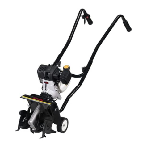
Yard Works GLT120CU User manual

model number 060-1809-8 | contact us: 1.866.523.5218
IMPORTANT:
Read and follow all safety rules and operating
instructions before using this product.
Instruction
Manual
10 A Electric Tiller
3025736

model number 060-1809-8 | contact us: 1.866.523.5218model number 060-1809-8 | contact us: 1.866.523.5218
2

model number 060-1809-8 | contact us: 1.866.523.5218 model number 060-1809-8 | contact us: 1.866.523.5218
3
model number 060-1809-8 | contact us: 1.866.523.5218
TECHNICAL DATA
Rated Voltage: 120 V~60 Hz
Rated Power : 10 A
No load speed: 390 RPM
Working width: 14’ (35.56 cm)
Working depth 7’ (18 cm)
Protection Class: /II
Machine Weight: 20 lbs (9.15 kg)
Table of ContentsTechnical Data
Technical Data 3
Product Safety 4
Know Your Tiller 7
Component List 8
Exploded View 9
Parts List 10
Assembly & Operation 11
Maintenance And Storage 16
Troubleshooting 16
Symbols 17
Warranty 18

model number 060-1809-8 | contact us: 1.866.523.5218model number 060-1809-8 | contact us: 1.866.523.5218
4
Important Safety Instructions
!WARNING: When using electric tillers,
basic safety precautions should always
be followed to reduce the risk of re, electric
shock, and personal injury, including the
following:
WARNING: Read all instructions
FOR ALL TILLERS
1) Avoid Dangerous Environments - Don’t
use tillers in damp or wet locations.
2) Don’t Use In Rain.
3) Keep Children Away - All visitors should
be kept at a distance from work area.
4) Dress Properly - Do not wear loose
clothing or jewellery.They can be caught
in moving parts. Use of rubber gloves
and proper footwear is recommended
when working outdoors. Wear protective
hair covering to contain long hair.
5) Use Safety Glasses - Always use face
or dust mask if operation is dusty.
6) Use the Right Tiller - Do not use tiller
for any job except that for which it is
intended.
7) Ground Fault Circuit Interrupter (GFCI)
protection should be provided on the
circuit(s) or outlet(s) to be used for
the gardening tiller. Receptacles are
available having built-in GFCI protection
and may be used for this measure of
safety.
8) Warning -To reduce the risk of electric
shock, use only with an extension cord
intended for outdoor use, such as an
extension cord of cord type SW-A,
SOW-A, STW-A, STOW-A, SJW-A,
SJOW-A, SJTW-A. or SJTOW-A.
9) Extension Cord - Make sure your
extension cord is in good condition.
When using an extension cord, be
sure to use one heavy enough to carry
the current your product will draw. An
undersized extension cord will cause a
drop in line voltage resulting in loss of
power and overheating. Table 1 shows
the correct size to use depending on
cord length and nameplate ampere
rating. If in doubt, use the next heavier
gauge. The smaller the gauge number,
the heavier the cord. To reduce the risk
of disconnection of tiller cord from the
extension cord during operating:
i) Make a knot as shown in Figure 1; or
ii) Use one of the plug-receptacle
retaining straps or connectors described
in this manual.
10) Avoid Unintentional Starting - Don’t carry
plugged-in tiller with nger on switch. Be
sure switch is off when plugging in.
11) Don’t Abuse Cord - Never carry tiller
by cord or yank it to disconnect from
receptacle. Keep cord from heat, oil, and
sharp edges.
12) Don’t grasp the exposed cutting blades
or cutting edges when picking up or
holding the tiller.
13) Don’t Force Tiller - It will do the job
!WARNING: Read all instructions.
!
WARNING: When using electric garden products, basic safety precautions
should always be followed to reduce the risk of re, electric shock, and personal
injury, including the following:
Product Safety

model number 060-1809-8 | contact us: 1.866.523.5218 model number 060-1809-8 | contact us: 1.866.523.5218
5
model number 060-1809-8 | contact us: 1.866.523.5218
properly and safer at the rate for which
it was designed.
14) Don’t Overreach - Keep proper footing
and balance at all times.
15) Stay Alert - Watch what you are doing.
Use common sense. Do not operate tiller
when you are tired.
16) Disconnect Tiller - Disconnect tiller from
the power supply when not in use, before
servicing, when changing accessories
such as blades, and the like.
17) Store Idle Tillers Indoors - When not in
use, tillers should be stored indoors in
dry, and high or locked-up place - out of
reach of children.
18) Maintain Tiller With Care - Keep
cutting edge sharp and clean for best
performance and to reduce the risk of
injury. Follow instructions for lubricating
and changing accessories. Inspect cord
periodically, and if damaged, have it
repaired by an authorized service facility.
Inspect extension cords periodically and
replace if damaged. Keep handles dry,
clean, and free from oil and grease.
19) Check Damaged Parts - Before further
use of the tiller, a guard or other part that
is damaged should be carefully checked
to determine that it will operate properly
and perform its intended function. Check
for alignment of moving parts, binding
of moving parts, breakage of parts,
mounting, and any other condition that
may affect its operation. A guard or other
part that is damaged should be properly
repaired or replaced by an authorized
service center unless indicated
elsewhere in this manual.
SAVE THESE INSTRUCTIONS
Table 1
Minimum gauge for extension cords
Volts Total length of cord
120 V 25’
7.2 m
50’
15.2 m
100’
30.4 m
150’
45.7 m
Ampere
rating
more than
not more
than
AWG
0-6 18 16 16 14
6-10 18 16 14 12
10-12 16 16 14 12
12-16 14 12 Not
recommended
Method of securing extension cord
CORD SET Tiller CORD
(A) TIE CORD AS
SHOWN
(B) CONNECT PLUG
AND RECEPTACLE
Figure 1
FOR ALL DOUBLE-INSULATED TILLERS
!WARNING: Read all safety warnings and instructions. Failure to follow
the warnings and instructions may result in electric shock, re and/or
serious injury.
Product Safety

model number 060-1809-8 | contact us: 1.866.523.5218model number 060-1809-8 | contact us: 1.866.523.5218
6
1) Replacement Parts
When servicing use only identical
replacement parts.
2) Polarized Connections
To reduce the risk of electric shock, this
tiller has a polarized plug (one Prong is
wider than the other) and will require the
use of a polarized extension cord. The
tiller plug will t into a polarized extension
cord only one way. If the plug does not t
fully into the extension cord, reverse the
plug. If the plug still does not t, obtain
a correct polarized extension cord. A
polarized extension cord will require the
use of a polarized wall outlet. This plug
will t into the polarized wall outlet only
one way. If the plug does not t fully into
the wall outlet, reverse the plug. If the
plug still does not t, contact a qualied
electrician to install the proper wall outlet.
Do not change the equipment plug,
extension cord receptacle, or extension
cord plug in any way.
SAVE THESE INSTRUCTIONS
Product Safety

model number 060-1809-8 | contact us: 1.866.523.5218 model number 060-1809-8 | contact us: 1.866.523.5218
7
model number 060-1809-8 | contact us: 1.866.523.5218
1. Handle bar
2. Switch Lever
3. Upper handle
4. Locking bolt for upper handle
x 2
5. Middle handle
6. Locking bolt for middle handle
x 2
7.
Lower handle
8. Wheel x 2
9. Tine shield
10. Outer tine x 2
11. Inner tine x 2
12. Motor housing
13. Locking knob for middle handle
x 2
14. Plug connector
15. Locking knob for upper handle
x 2
16. Cord retainer
17. Lock-out Button
18. Hitch pin
19. Wheel assembly
20. Connector for wheels
21. Clamping bolt
Know Your Tiller

model number 060-1809-8 | contact us: 1.866.523.5218model number 060-1809-8 | contact us: 1.866.523.5218
8
1
2
3
4
5
6
7
8
10
11
12
13
15
16
14
9
17 21
20
19
18
We recommend that you purchase your accessories from the same store that
sold you this product. Refer to the accessory packaging for further details.
Store personnel can assist you and offer advice.
Component List

model number 060-1809-8 | contact us: 1.866.523.5218 model number 060-1809-8 | contact us: 1.866.523.5218
9
model number 060-1809-8 | contact us: 1.866.523.5218
3
4
5
6
7
9
10
11
12
13
14
17
18
15
16
19
20
22
48
47
25
23
24
26
27
28
29
30
32
33
34
35
36
37
38
39
40
41
42
43
44
45
46
31
21
849
2
1
Exploded View

model number 060-1809-8 | contact us: 1.866.523.5218
10
Item Description QTY.
1 switchgear cabinet 4 1
2 switchgear cabinet 3 1
3 torsional spring 1
4 screw-M4X10 1
5 trigger bar 1
6Bale lever 1
7 Upper handle assembly 1
8 Cord retainer 1
9 switchgear cabinet 2 1
10 spring 1
11 trigger bar 1
12 power door unlock 1
13 tension spring 1
14 switch 1
15 pressing plate 3
16 Bolt 4
17 screw-ST4X16 14
18 protecting bush 2
19 switchgear cabinet 1 1
20 Hang for power cord 2
21 attaching plug 1
22 power line 1
23 intermedium tube 2
24 Lower handle 1
25 upper revit board 1
26 loam cake 1
27 decorative sheet 2
28 fuselage cover 1
29 wind board 2
30 Motor assembly 1
31 cover board 2
32 jump ring 2
33 wheel 2
34 baseplate 1
35 tine 2
36 coupler 1
37 junction plate 1
38 screw-M8X40 2
39 nut-M8 2
40 gear box assembly 1
41 nut-M6 4
42 screw-ST6X25 8
43 screw-M6X20 4
44 wheel shelf assembly 1
45 alignment pin 1
46 plug pin 1
47 lower revit board 1
48 knob 4
49 Sponge sheath 1
Item Description QTY.
Parts List

model number 060-1809-8 | contact us: 1.866.523.5218 model number 060-1809-8 | contact us: 1.866.523.5218
11
MOUNTING
Proper use
This tiller is only intended for scarifying/aerating (loosening and aerating of the lawn). It is only
suitable for domestic use in home and hobby gardens.
Improper use
The tiller must not be used in permanent operation and not in industrial environments.
ASSEMBLY
This product must be assembled correctly before use.
!WARNING! Do not connect to power supply until assembly is complete. Failure to comply
could result in accidental starting and possible serious personal injury.
1.FITTING THE CORD RETAINER (See Fig. A)
Simply attach the cord retainer (16) by inserting it through the upper handle (4).
2.FITTING THE HANDLE
Assembling the middle handle with lower handle (SEE FIG. B1)
1) Attach the middle handle to the lower handle, align the hole on the middle handle with the
hole on lower handle.
2) Insert the locking bolt (6) for middle handle through the aligned holes on middle and lower
handles.
3) Insert the locking knob (13) for middle handle through the bolt and turn it clockwise to
tighten.
4) Repeat the above steps to assemble the other side of the middle handle.
Assembling the middle handle with upper handle (SEE FIG. B2)
5) Attach the upper handle to the middle handle, align the hole on the middle handle with the
hole on upper handle.
6) Insert the locking bolt (4) for upper handle through the aligned holes on middle and upper
handles.
7) Insert the locking knob (15) for middle handle through the bolt and turn it clockwise to
tighten.
8) Repeat the above steps to assemble the other side of the upper handle.
3.FITTING AND ADJUSTING THE WHEELS
The wheels are used to control the depth of operation and for transport.
Assembly & Operation

model number 060-1809-8 | contact us: 1.866.523.5218
12
Assembling the wheels (SEE FIG. C1, C2):
1)
Insert the wheel assembly (19) into the connector for wheels (20) on the machine. (See Fig. C1)
2) Choose a desired hole on the wheel assembly (a) according to the required height. Align
the hole with the hole (b) on the connector for wheels.
3) Slide the clamping bolt (21) provided through the aligned holes. (See Fig. C2)
4) Insert the hitch pin (18) through the hole on the bolt lock the wheel assembly. (See Fig. C3)
Adjusting the wheels (SEE FIG. C4):
Remove the hitch pin and the clamping bolt, move the wheel assembly upwards or downwards
to a desired position. Re-tighten the hitch pin to the bolt to lock the wheels.
NOTE: The wheels can be removed (i.e. tilling without the wheels) for the greatest tilling depth.
OPERATION
!WARNING: Never operate the tiller without the proper safety devices in place and
working. Never operate the tiller with damaged safety devices. Operation of this
product with damaged or missing parts could result in serious personal injury.
!WARNING:
•Do not allow hands, feet, or any other part of the body or clothing near the rotating
tines or any other moving part.
•The tines continue to rotate until the switch trigger is released. Failure to avoid
contact could cause serious personal injury.
1.STARTING AND STOPPING
To start (See Fig. D):
1) Plug the tiller into an approved outdoor extension cord.
2) Press the lock-out button and press the switch lever against the handle bar to start the tiller.
Release the lock-out button while continuing to hold upward on switch lever to continue use.
To stop:
Release the switch lever to stop the tiller. Allow sufcient time for the rotating parts to come to
a complete stop.
!WARNING:
•If any parts are damaged or missing do not operate this product until the parts are
replaced.
•Failure to heed this warning could result in serious personal injury. Call our
customer service help line.
•Do not attempt to modify this product or create accessories not recommended for
use with this product. Any such alteration or modication is misuse and could result
in a hazardous condition leading to possible serious personal injury.
2.USING THE CORD RETAINER
This tiller is equipped with a cord retainer in order to prevent the extension cord from
disconnecting from the power cord while the tiller is in use.
Assembly & Operation

model number 060-1809-8 | contact us: 1.866.523.5218 model number 060-1809-8 | contact us: 1.866.523.5218
13
To use the cord retainer:
1) Fold the extension cord in order to form a tight loop. Push the loop through the rectangular
hole in the retainer. (See Fig. E1)
2) Slide the loop over the retaining clip, and pull down until the cord is secured. (See Fig. E2)
3.PREPARING THE SEED BED
The tiller can be used to break up the garden soil and prepare a seed bed for planting. Plan
ahead to leave enough room between the seed rows to allow for machine cultivating after the
plants have grown.
TILLING SOD
Tilling sod into the soil is not recommended. If sod must be removed to perform application,
then it is suggested to do as follows:
1) Map out the area of sod required to be removed.
2) Cut into 16˝ x 36˝ (40 x 81 cm) sections using a spade shovel or edger at a depth of 3’’ (7.7
cm).
3) Lift the sod from the edges using a shovel, sliding below at the roots.
4) Remove the sod. Carry sod to compost pile or ground that requires ll. Turn the sod upside
down to allow grass to decompose.
5) Once sod layer is removed, begin to till the soil to desired depth.
ATTENTION:
•Move the tiller to the work area prior to starting the motor.
• Hold the tiller rmly while starting. The tines will pull the tiller forward during operation.
Lower the tines slowly with the guide bar.
• By pulling the tiller back towards yourself, the tines will dig deeper and more aggressively.
•To keep tripping, take extra precautions when moving backwards and when pulling the tiller
back toward yourself.
•If the tiller digs deep enough to stay in one spot, gently rock it side to side until it starts
moving forward again.
•Never pass the tiller over the extension cord. Make sure the cord is always in a safe
position behind you.
• When working on inclines always stand diagonally to the incline to retain a rm, safe
footing. Do not work on steep slopes.
WORKING HINTS FOR TILLING:
1.
With the wheel assembly installed to the desired depth position, roll the tiller to the work area.
2. Plug the tiller into an approved extension cord.
3. Stand behind the tiller, with tines on ground and the work area clean and free of
obstructions.
4. Start the tiller to work.
!IMPORTANT: If weeds, roots, vines or other growth gets collected around the
bottom of the tiller/cultivator it is important to stop tiller/cultivator. Disconnect from
power source and clean tines using a screwdriver or other object which can help remove
debris. If necessary, removes tines to untangle debris from shaft and tines.
Assembly & Operation

model number 060-1809-8 | contact us: 1.866.523.5218
14
b
a
a
1
2
13
15
6
4
AB1
B2 C1
C2 C3
C4 D
I E2
E1
Assembly & Operation

model number 060-1809-8 | contact us: 1.866.523.5218 model number 060-1809-8 | contact us: 1.866.523.5218
15
b
a
a
1
2
13
15
6
4
AB1
B2 C1
C2 C3
C4 D
I E2
E1
Assembly & Operation

model number 060-1809-8 | contact us: 1.866.523.5218
16
MAINTENANCE AND STORAGE
Attention: Before carrying out maintenance operations, disconnect power supply.
•Clean dirt, grass, and other materials from the entire unit.
•Wipe the tines with oil or spray them with a silicone lubricant to prevent rusting.
•Oil the switch trigger cable and all visible moving parts.
•Order new parts to replace any that are badly worn or broken.
•Store in an upright position in a clean, dry place out of reach of children. Store with the
handles in the extended position, or loosen handle knobs and fold the handles down.
Do not allow ngers nor the switch trigger cable to become pinched when lowering the
handlebar.
•During extended periods of storage, ensure that the tiller is protected against corrosion and
frost.
TROUBLE SHOOTING
Problem Possible causes Remedy
Motor does
not start
1. Unit not plugged....
2. No Electricity
3. Defective Table...
4. Defective Safety
Switch plug
5. Overheat
Protection activated
Plug in the unit
Check power supply
Check cable. Repair or replace if required
Arrange for repair
1. Working depth too large, set to a shorter depth.
2. Blades blocked, remove the blockage.
3. Soil too hard, select correct work depth and
move forward and backward several times while
slowing down the operation speed.
Wait until the motor cools down for about 15 minutes
before further use.
Abnormal
noises
1. Blade is jammed
2. Lubrication running
out
3. Bolts, nuts or other
components are
loose.
Switch off. Wait till tines comes to a complete stop.
Remove jammed objects.
Tiller must be repaired. Call our customer service
help line.
Tighten all components. Arrange for repair if noises
continue.
Abnormal
vibrations
1. Blades damaged
or worn
2. Working depth too
large
Replace damaged or worn blades.
Set to correct working depth.
Poor results 1. Working depth too
small Set to correct working depth.
Maintenance And StorageTroubleshooting

model number 060-1809-8 | contact us: 1.866.523.5218 model number 060-1809-8 | contact us: 1.866.523.5218
17
Symbols
Symbol Name Designation/Explanation
V Volts Voltage
A Amperes Current
Hz Hertz Frequency (cycles per second)
W Watts Power
min Minutes Time
Alternating Current Type of current
Direct Current Type of current
Class II Construction Double-insulated construction
/min Per Minute Revolutions, strokes, surface speed, orbits etc., per minute.
Read The Operator’s
Manual To reduce the risk of injury, user must read instruction manual.
Ear Protection Wear ear protection.
Operation condition Do not expose to rain.
Read operator’s manual
Warning
WARNING – Beware of sharp tines, keep ngers and
toes away. Remove plug from mains before maintenance,
adjusting, cleaning or if the cord is entangled or damaged.
Tines continue to rotate after the motor is switched off
Keep bystanders away
SAVE THESE INSTRUCTIONS!

model number 060-1809-8 | contact us: 1.866.523.5218
18
TWO-YEAR LIMITED REPAIR WARRANTY
For two (2) Years from the date of purchase
within Canada, YARDWORKS CANADA
will, at its option, repair or replace for the
original purchaser, free of charge, any part
or parts found to be defective in material or
workmanship.
THIS WARRANTY DOES NOT COVER
1. Any part that has become inoperative
due to misuse, commercial use,
abuse, neglect, accident, improper
maintenance, or alteration;
2. The unit, if it has not been operated and/
or maintained in accordance with the
owner’s manual;
3. Normal wear, Including but not limited to:
Routine maintenance items such as
lubricants, blade sharpening; or Normal
deterioration of the exterior nish due to
use or exposure.
FULL ONE HUNDRED TWENTY (120) DAYS
WARRANTY ON NORMAL WEAR PARTS
Normal wear parts are dened as blade
adaptors, blades, grass bags and tires.
These parts are warranted to the original
purchaser to be free from defects in
material and workmanship for a period of
one hundred twenty (120) days from the
date of retail purchase.
HOW TO OBTAIN SERVICE
Warranty service is available by calling
the toll-free helpline, at 1.866.523.5218.
The factory will not accept the return of a
complete unit unless prior written permission
has been extended by YARDWORKS
CANADA.
TRANSPORTATION CHARGES
Transportation charges for the movement
of any power equipment unit or attachment
are the responsibility of the purchaser.
The purchaser must pay transportation
charges for any part submitted for
replacement under this warranty unless
such return is requested in writing by
YARDWORKS CANADA.
OTHER WARRANTIES
All other warranties, express or implied,
including any implied warranty of
merchantability is limited in its duration to
that set forth in this express limited warranty.
The provisions as set forth in this warranty
provide the sole and exclusive remedy of
YARDWORKS CANADA obligations arising
from the sale of its products.
Made in China
Imported by Yardworks Canada,
Toronto Canada M4S 2B8
Warranty

model number 060-1809-8 | contact us: 1.866.523.5218

Made in China. Imported by Yardworks Canada
Toronto, Canada M4S 2B8
This manual suits for next models
1
Table of contents
Other Yard Works Tiller manuals