Yardbird MIG-29 Park Jet User manual

MIG-29 Park Jet
INSTRUCTION MANUAL
Warranty
The contents of this kit are guaranteed to be free of defects at time and date of purchase. The warranty
doesn’t cover modifications to kit, or damage to Components used in combination with this product. Yardbird
RC will only cover the replacement of this kit for defects at time of purchase.
Liability
Yarbird RC has NO control over final assembly of this product and or materials used in the final assembly
process. Yard ird RC assumes NO liability for the final user assembled product. The user of this product
assumes all liability for the final assembly of this product and any damage caused in its operation
and use.
Please return this kit to the place of purchase in a new and unused condition for refund, if the purchaser is
not prepared to accept liability for the operation and use of this product.
Read this assembly manual before starting construction. It contains Tips, and important
construction instructions. Please read all information enclosed in this manual and
information enclosed in products to be used in combination with this product.
Wing Span: 24 Inches.
Length: 34. Inches.
Flying Weight: 9. -13. Ounces.
Radio: Requires Three Channels, V-Tail Mixing.
Recommended Motor: DUALSKY XM2826CA-12 Brushless Outrunner.
Yard ird RC
39 E. Gasligh
t PL
The Woodlands, TX 77382
Phone/Fax: (281) 298 -5862

2
TABLE OF CONTENTS
Thank You……………………………………………...
Safety First……………………………………………...
Building Instructions…………………………………...
Additional Building Materials………………………….
Recommended Electronics………………......................
Kit Contents…………………………………………….
Kit Construction………………………………………..
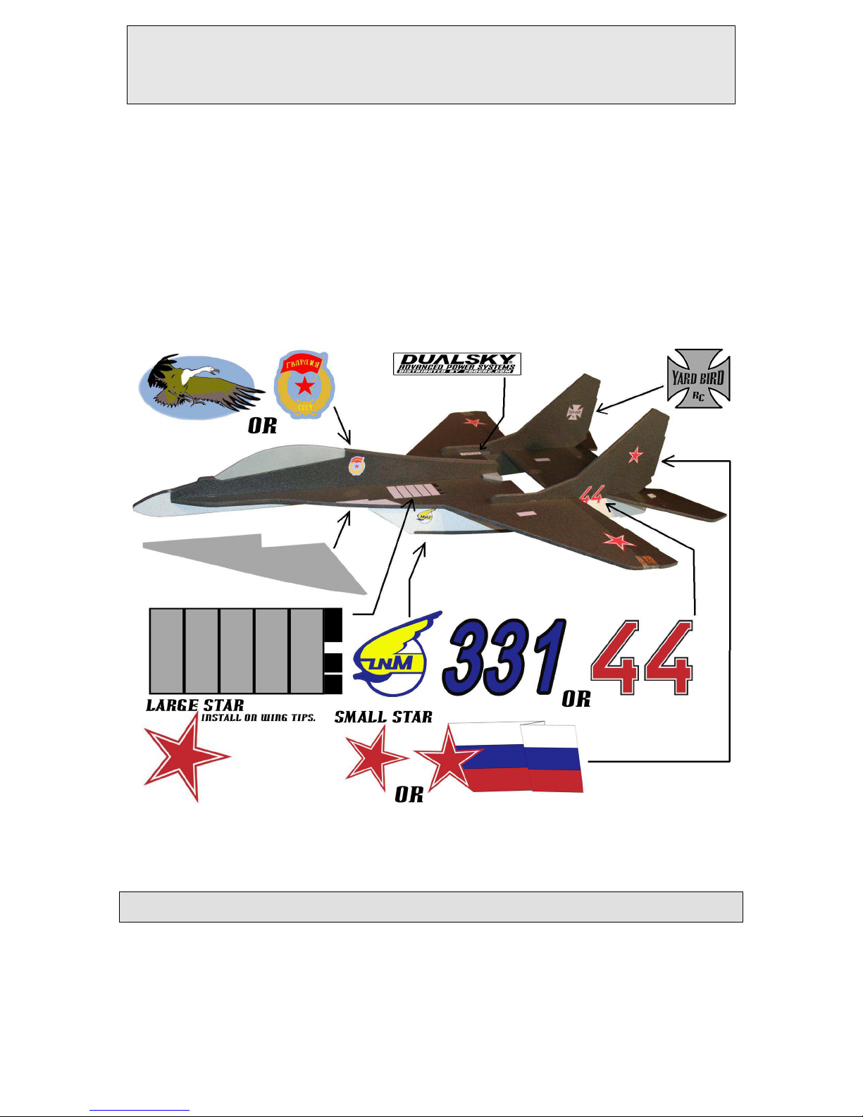
Paint and Decal Installation…………………………….
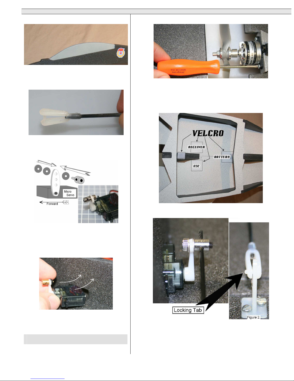
Servo and Push Rod Installation………………………..
Setup……………..……………………………………..
General…………………………………………………
Preflight………………………………………………..
First Flight……………………………………………..
Thank You
Thank you for your purchase of the Yardbird RC
Mig-29 Park Jet. It is our sincere hope that this product
will bring you many hours of fun and safe enjoyment.
This kit is primarily designed as a park flyer and has
been tested in light winds up to MPH. Please look for
the Yardbird RC YB-22 to complete the ultimate dog
fighting experience. Yardbird RC is proud of this kit
and we know that you will be happy with the quality
found inside the box. This kit was proudly
manufactured in the USA.
Yardbird RC
Safety First
This product is intended for use as a RC aircraft
for intermediate to advanced pilots. It should not be
used or thought of as a Toy. This product is capable
of speeds in excess of 0 MPH, and just like real
aircraft this model could cause damage to people or
property. Do not operate this kit in the vicinity of real
aircraft or groups of people. This model has a mid-
mounted propeller. This design feature is safer then a
nose or tail mounted prop. However special care should
be used around the propeller. Propellers can cause
damage and injuries. Please check local laws,
restrictions and park rules in your area in regards to
operating RC aircraft. Joining a local RC aircraft club
is a great idea. Your local hobby shop will have
information on local RC clubs. If you are not
experience with this type of RC model seek out the
help of an experienced RC pilot or instructor for your
first few flights.
Please take your time in building your kit. Follow the
directions in this manual. You must build this kit strong
and true. Do not alter or modify this kit, it will change
the flight characteristics in ways that may not be
predictable. Yardbird RC has worked diligently to
provide a quality kit. However the final assembly
and airworthiness of this kit will depend on how you
build it. Because Yardbird RC has no control over the
final assembly of this kit we don’t guarantee the flight
characteristics safety or airworthiness of this kit.
Pg. 2
Pg. 2
Pg. 2
Pg. 2
Pg. 2
Pg. 3
Pg. 4
Pg. 7
Pg. 9
Pg.10
Pg.10
Pg.11
Pg.11
Building Instructions
Each step is numbered so follow the order; don’t
skip ahead. The picture or pictures for each step is
placed before the written instructions. You should
look at the picture and read the instructions
thoroughly before completing each step.
Glue: Read the instruction for the glue you decide
to use with this kit. Use only foam safe glue. Use the
test piece of foam to test the glue before using it on
the rest of the kit. Remember glue adds weight. Too
little glue and the joint will be weak; too much the
aircraft will lose performance or not fly at all. We
recommend that you use Yardbird RC Ultimate RC
Foam Glue for the best results.
Test Fit:
Means to assemble the pieces without
glue.
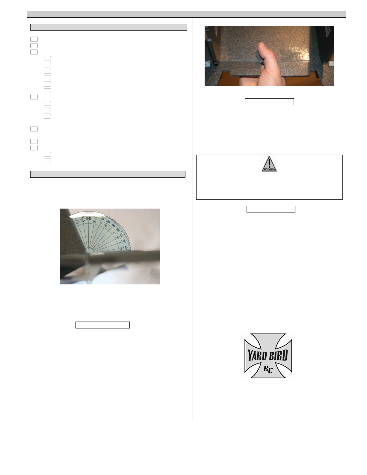
Attention triangle: When you see this symbol
pay attention to the important instructions or
notes.
Additional Building Materials
- Foam glue: Yardbird RC Ultimate RC Foam Glue.
- CA glue: (Cyanoacrylate Glue) or Super Glue.
Only used for one step. A small bottle or tube
will work.
- X-ACTO knife with number 11 blade.
- 1. MM hex head wrench.
- Small cross point screw driver.
- Painters tape. Optional.
- Foam Safe Paint. Optional.
Recommended Electronics
Motor: DUALSKY XM2826CA-12
Brushless Outrunner.
Prop: ACP 7X .
Electronic Speed Control: DUALSKY XC1812BA.
attery: DUALSKY XP13003GT.
Radio Controller: This kit requires three channels
and v-tail mixing. A 2.4 GHz radio is
recommended for park flyers. Due to the reduced
risk of radio interference.
Please read all warning and setup information
enclosed in products to be used in combination
with this kit.
LITHIUM POLYMER ATTERYS
Can catch fire or explode. Always use and
maintain the manufacture recommendations!

3
Kit Contents
Part Name
Part #
1
2
3
4
6
7
8
9
10
11
12
13
14
1
16
17
18
19
Canopy
Upper Fuselage
Upper Fuselage
Lower Fuselage
Lower Fuselage
Left Wing Deck
Right Wing Deck
Aft Wing Deck
L Vertical Stabilizer
R Vertical Stabilizer
Left Elevon
Right Elevon
Left Aft Fuselage
Right Aft Fuselage
Belly Plate
Access Door
Aft Brace
Aft Brace
Nose Deck
Not Shown
0129
0229
0229
0329
0329
04L29
0 R29
06L29
06R29
07L29
08R29
09L29
10R29
11L29
12R29
1329
1429
1 29
1629
Part Name Part #
1
2
3
4
6
7
8
9
10
11
12
13
14
1
Control Horns (2)
Control Horn Screw (4)
Engine Mount
E/Z Connector (2)
Deleted
Deleted
Velcro Strip
Fiber Hinge (3 sets)
Clevis (2)
Carbon Fiber
24 Inch Wing Spar
9. Inch Control Rod (2)
6 Inch Elevon Rod (2)
12 Inch Aft Fuselage
Rod
Engine Mount Screws
Not Shown
Decal Sheet
1629
1729
1829
1929
2029
2129
2229
2329
2429
2 29
2629
2729
2829
2929
3029

4
Kit Construction
Step 1.
Use care with the X-ACTO knife!
Use the X-ACTO knife to remove the milling tabs on all
the foam parts.
Step 2.
Test fit the left and right wing deck to the nose deck
piece. Make sure that the surface being used to work on is
completely flat. Glue the three pieces together. Use two
large books to hold the pieces together and flat against
the table until glue is set.
Step 3.
Glue the flat side of the 24 inch carbon fiber wing spar
to the aft wing deck.
Step 4.
Test fit and glue the 12 inch long carbon fiber rod into
the channel at the bottom of the aft wing deck.
Step 4.1
Test fit and glue the 6 inch pieces of carbon fiber into the 6 inch
channels in the elevons.
Step 4.2
Critical step.
Flip the aft wing deck over so that the gray side is up. Apply hinge tape
to the left elevon hinge joint as show above. Repeat for the right side.
Step 5.
With the white sides up. Firmly glue and press the wing deck
assemblies together. Use two large books to hold the pieces together and
flat against the table until glue is set.
Step 6 .
Test fit the aft fuselage pieces into place. They should fit as pictured
above. White sides should face out.

Step 6 .1
Glue the aft fuselage pieces flush with the edge as shown
above. Don’t apply glue to the 1 inch by ½ inch servo
slots. Glue the aft fuselage pieces into place. Use two
large books to hold the wing deck assembly flat against
the table. This is ery important. If not used the deck
could warp. Don’t remo e books until glue is set.
Step 7.
Glue the two lower fuselage pieces together.
Step 7.1
Test fit the lower fuselage assembly to the wing deck
assembly as pictured above. After test fitting glue the
pieces together.
Step 8.
Use the X-ACTO knife to cut 2 separate ½ inch long
slots in the end of the access door opposite of the round
hole. Then install fiber hinges. Do not glue. Take your
time.
Step 9.
Cut the two separate ½ slots for the opposite end of the fiber hinges.
Now slip the fiber hinges into the belly plate slots to complete the step.
Do not glue the fiber hinges to the belly plate. Only glue the fiber
hinges to the access door so the door can be completely removed for
access to the battery and electronics. Add a small drop of glue to the tip
of the fiber hinges and then slid them into the ½ inch slots. Remove the
access door for the next few steps.
Step 10.
Test fit the belly plate to the aft fuselage and lower fuselage pieces as
pictured above. Note e ery place the three pieces come in contact with
each other. You will need to glue all the points of contact. Take your
time on this step you may ha e to push the aft fuselage pieces inboard to
get the edges to line up perfectly with the belly plate. The two aft
extensions of the belly plate can be held in place with painters tape until
glue sets. After test fitting glue the pieces to together.
Step 11.
Test fit and glue the brace together. Glue the gray sides together.

6
Step 12.
Test fit and glue the brace assembly into the fuselage as
pictured above. Take care to glue the brace on top of and
parallel to the joint between the right and left wing deck.
Glue all the points of contact with the fuselage including
the engine mount.
Step 13.
Glue the two upper fuselage pieces together. Same
technique as step 11.
Step 14.
Test fit and glue the upper fuselage assembly to the top
side of the wing deck as show above.
Step 15.
Test fit and glue the vertical stabilizers as shown in the
picture above. Make sure that these two pieces are firmly
glued in place.
Step 16.
Cut a 1/2 inch section from the Velcro strip. Attach it to the inside of
the access door aft of the round hole.
Step 17.
Use a small drop of glue to secure the control horn to the bottom side
of the elevon. Gently push the two screws threw the two holes in the
elevon. Then secure the back plate to the other side of the elevon with
the two screws and a drop of glue.
Step 18.
Install Engine mount. The holes drilled in the engine mount are sized
for the recommended DUALSKY XM2826CA-12 Brushless Motor
.
If you
use a different power system you may ha e to drill new mounting holes.

7
Paint and Decal Installation
Step 19.
Paint
Paint is optional. Paint adds weight and painting the entire model is not recommended. Always use foam safe paint.
Test all paints on the test piece before applying to the model. Always paint in a well ventilated area and follow the
directions for the paint chosen.
Paint used for the cockpit below was TESTORS 1238 Gloss Gray. Remember to always test first.
Step 20.
Decals
The decals are installed as pictured above. The decals are printed on a ultra thin vinyl. Lightly rub the decals after
they are in place to secure them. The vinyl adhesive will set completely after 24 hours.

8
Ser o and Push Rod Installation
Step 21.
Test fit and glue the cockpit in place as shown in the
above picture. If you plan to paint the kit you may wish to
glue the cockpit on after painting.
Step 22.
Use the CA glue or super glue to attach the clevis to one
end of the 9. inch carbon fiber rod. Repeat step for the
both 9. inch rod.
Step 23.
The servo arms should be installed at a 90 degree
angle as depicted above. Install the E/Z connectors
on the servo arms as shown above. Put a small drop
of CA glue or thread locker on nut and threads after
tightening.
Step 24.
Gently slide the servos into the servo slots. Glue
the servo in place after setup is complete.
Step 25.
Attach the motor to the engine mount using the motor mount screws.
Position the motor so the three wires exit the bottom side of the airframe.
On APC props the APC lettering should face the motor (forward).
Step 26.
Recommended Electronics installation
Use the Velcro to secure the electronics and battery in the compartment under the
access door.
Step 27.
Slide the free end of the carbon fiber control rod into the E/Z connector as
illustrated above. Attach the clevis end to the second hole down on the control
horn (Figure 2.). Make sure the locking tab is exposed as shown above. Use the
hex head screw on the E/Z connecter to securely hold the carbon fiber in place.

9
Setup
Step 28.
Setting Control Direction
Take care around the prop. You may wish to remo e or wait to
install the prop until after the control direction setup.
Power Up the transmitter and receiver. Center all the trim levers. With
the trim levers centered check the two elevons. They should be even. You
may have to loosen and retighten the screws on the E/Z connectors after
re-adjusting the control rods.
Nose Up
Nose Down
Turn/Roll Right
Turn/Roll Left
Make sure the elevons move in the correct directions as illustrated
above. If the servos move in the wrong direction use the servo reversing
on the transmitter to get the correct movement. After adjusting is
complete recheck to make sure the trim and control surfaces remain
centered. The elevons up and down range from center should be about 33-
3 degrees.
Center of Gravity
Center of gra ity or C.G. (the balancing point of the model)
can affect flight performance drastically. Failure to correctly
balance the model will result in an un-flyable aircraft.
Step 29.
Make a mark using a felt tip marker at 2.12 inches from the back of
the engine mount. This will indicate the ideal C.G. position for the
aircraft.
Step 30.
(YARDBIRD RC YB-22 sho n above.)
Always perform C.G. checks with all the gear installed. The model
in the illustration is balance correctly. With all gear installed the
aircraft should be between
9. -13. oz.
Mo ing the battery location is
the most effecti e way of changing the C.G.
The C.G. jig illustrated abo e was simply made by gluing two 10
inch rods into a block of foam. Then screwing two wire caps on top
of the rods.
Step 31.
Final uilding Notes
It is recommended to rap a 1 x 3 inch piece of clear packing tape
around the top and bottom of the wing tip as illustrated above.
Install 1/8 oz of ballast on the right wing. Pushing a finishing nail
into the wing tip works great.
General
Good Job, you’ve finished a great looking model and you’re
dying to go fly it! Well there are a few things to remember before
that first critical flight.
1. You must do a ground range check of the radio equipment used
in the aircraft.
2. Remember to get assistance from an experience pilot if you are
not familiar with this type of RC model.
3. Don’t fly with spectators until you are competent and safe with
the flight of this model.
4. Don’t fly within three miles of an airport.
. Don’t fly within three miles of a pre-existing flying field unless
you are in accordance with a frequency sharing agreement.
6. Don’t try and catch or touch the model in flight.
7. Do not use this model with pyrotechnics (firecrackers, rockets,
rocket motor
s, projectile, fuel of any kind, anything that explodes or
burns).
8. Remember to use common sense. If it doesn’t seem right it
probably isn’t. Park flyers must be courteous and considerate of
others. Don’t abuse the park or field rules. Remember never to fly
over people or property.
9. Never apply full power in a dive of steep decent.

10
Preflight
Preflight Check list
1. Perform a range check with the radio.
2. Always perform a C.G. check before flying.
3. Make sure the electronics are installed securely. Check that the
servos are glue in tight.
servo arms are attached with the proper screws.
E/Z connectors are tight and you can see the brass tab.
battery is attached securely.
receiver and electronic speed control are secure.
The motor and engine mount are securely attached.
4. Check the elevons. Check that the
hinges are attached securely.
control horns are secure and all hardware is attached.
clevises is attached correctly with the locking tab
exposed.
. Check the controls move and the correct direction. And
throws are set to low rate for the first flight.
6. Check the operation of the motor.
7. Check the overall condition of the foam. Check that the
joints are all firmly glued.
carbon fiber pieces are firmly attached.
First Flight
The first flight should be about getting used to the way this model
handles and flies. Be ready to add a little nose up trim. 4-6 degrees of
trim is a good starting point.
This aircraft has a wide speed range so be prepared to make slight trim
adjustments for different airspeeds. It’s not recommended to attempt high
speed runs on the first flight. Just take it easy. Get the model trimmed out
at get comfortable with it.
Launching the Model
On the first flight it is recommended to have a assistant launch the
model so that the pilot can concentrate on flying. The recommended
technique for assisted launch is for the thrower to grasp the wing tips
with there thumbs on the top side of the wings and gently toss the model
at a 30 degree nose high attitude. Simultaneously the pilot should add ¾
power and climb to a safe altitude.
Once you have got the aircraft trimmed out and a familiar and
comfortable with the launch and climb out. The alternate launch method
is to lightly grasp the model with you right hand. Your thumb in the gap
between the two elevons and your fingers spread under the aft wing deck.
Hold the aircraft at a 30 degree nose high attitude adding ¾ power and let
the model fly out of your hand.
This illustration shows the alternate launch method.
Flight
Once at a safe altitude gently guide the model around the pattern
at ½ power. Get the aircraft trimmed out for straight and level
flight. Take some time and get comfortable with it. Try some slow
flight. Try some practice landing approaches. Remember to relax
and think ahead of the aircraft. Fly the airplane the entire time, if
you take a mental brake you may break something else.
attery
Always monitor you battery le el, this type of aircraft doesn’t
fly well without power. If for some reason you loose power
immediately lower the nose and make a steep approach to land.
Landing
It’s good to make a few practice approaches before you attempt to
land. This model is capable of ery low airspeed. And you should
be able to make spot landings with a little practice. Remember to
land into the wind.
Start by reducing power to ½ and inter the down wind leg at
about 0 feet above the ground. Make a wide descending turn to
final approach reducing power to ¼ or less depending on the wind.
As you approach the spot of intended landing slowly reduce power
to idle and about 3 feet above the ground allow the airframe to
make a pizza box flop type landing. Gently floppy down preferably
in soft grass. It may take a little practice but you should be able to
touch down softly with no forward skidding. Remember to idle
the prop before touch down. That’s it.
Good work, Now go fly!
MIG-29 Park Jet
Table of contents
Popular Toy manuals by other brands

The World Models Manufacturing
The World Models Manufacturing SPITFIRE - 60 instruction manual

Carrera
Carrera 25195 FORMULA ENGINES Assembly and operating instructions

Mattel
Mattel Hot Wheels Marvel Avengers Infinity War Avengers vs Thanos... instructions

LEGO
LEGO Mindstorms 51515 quick start guide

Hasbro
Hasbro FURREAL F2539 quick start guide

roco
roco 71778 operating manual