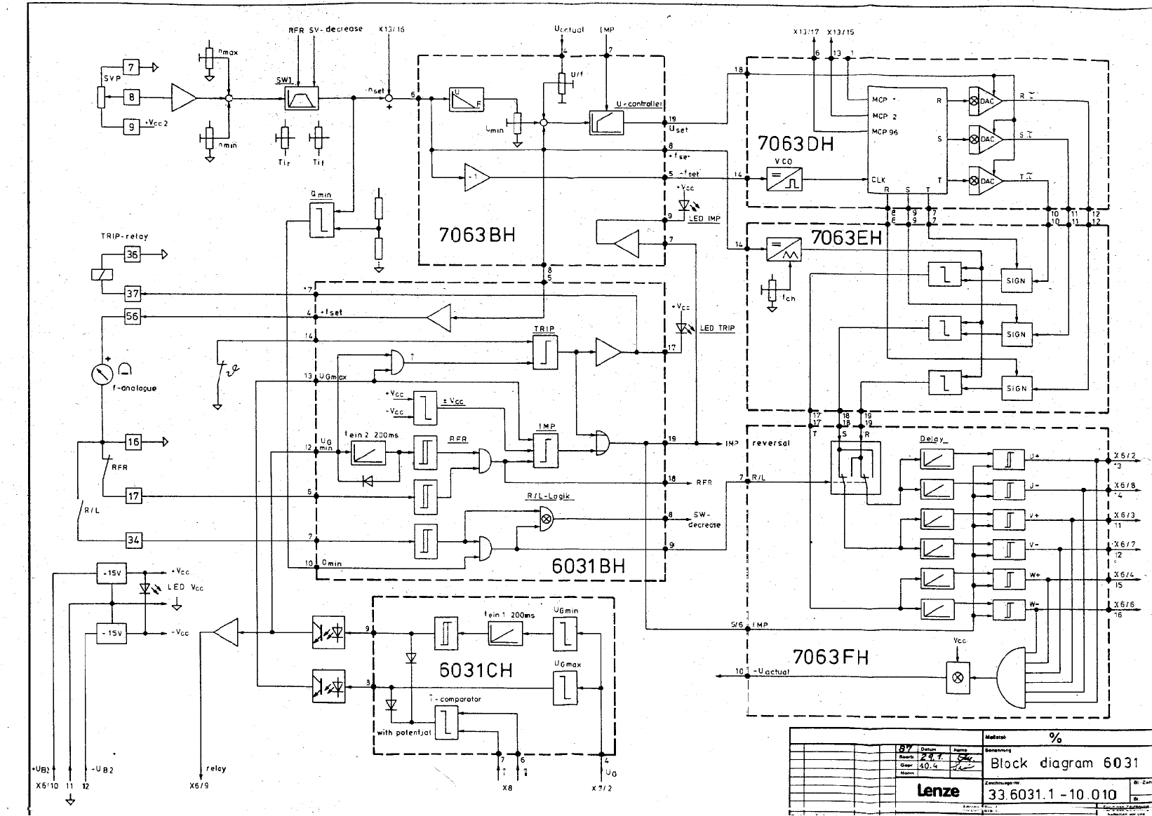
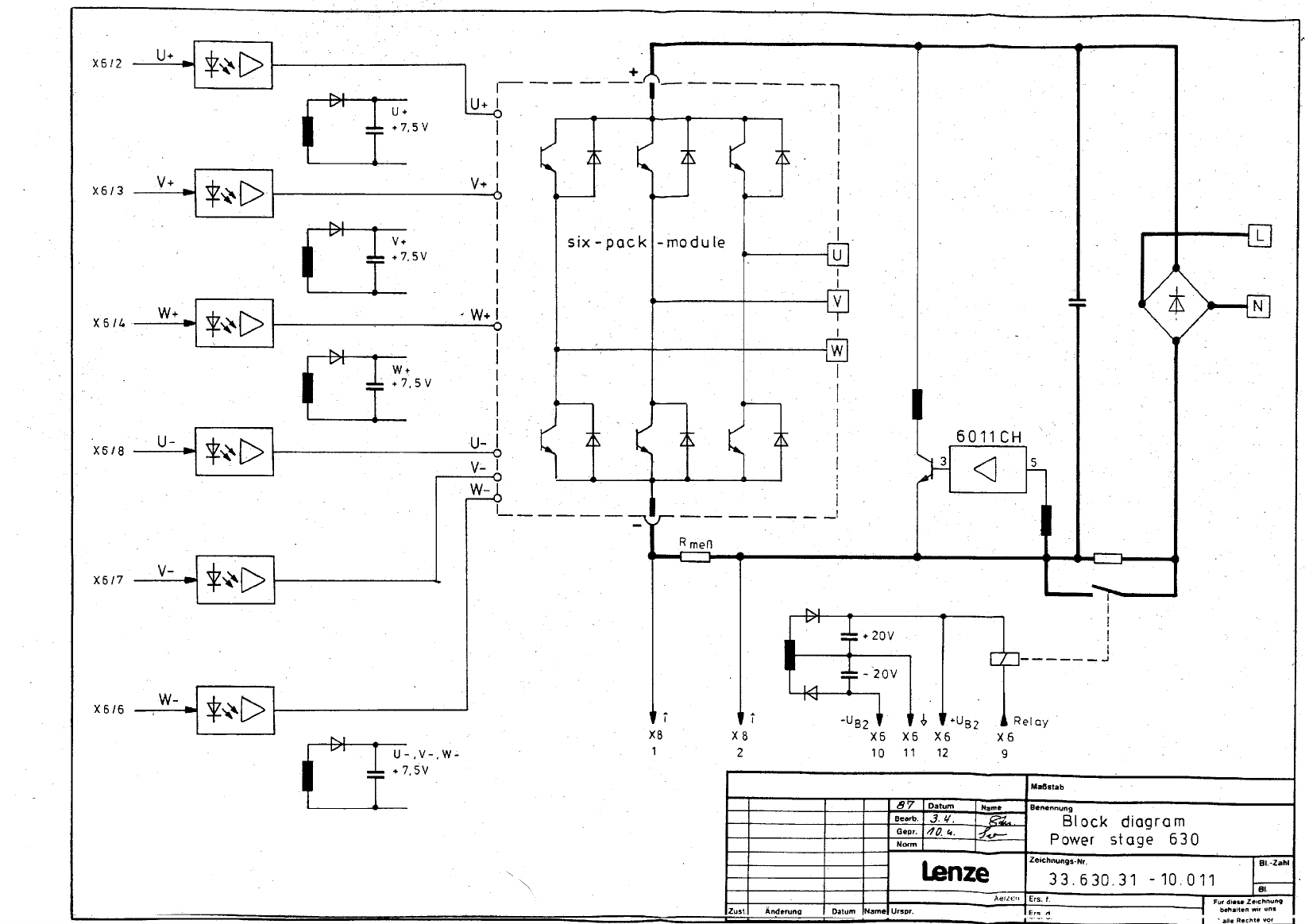
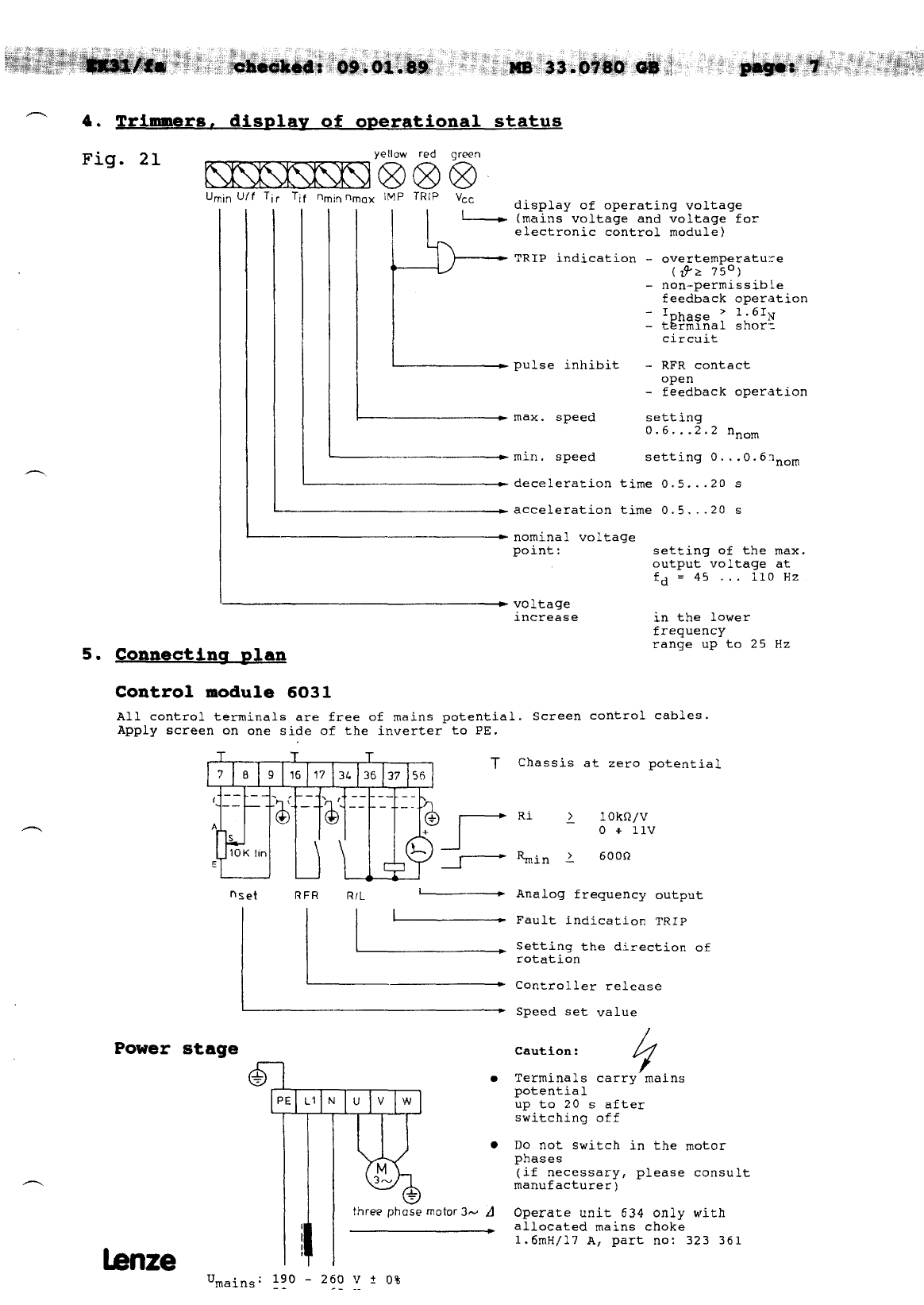
Lenze 630 Series Operating instructions


26.10.1989

-
Table of contents
1.
2.
3.
3.1
3.2
4.
5.
6.
6.1
6.2
6.3
- 6.4
7.
8.
8.1
8.2
8.3
8.4
9.
10.
General information 2
Technical data, fuses, mains chokes 'i2 - 3
Block diagram 631 - 634 4
Block diagram 6031 control stage 5
Block diagram 630 power stage 6
Trimmers, display of operational status 7
Connecting plan 7
Overall connecting plans 8 - 11
Overall connecting plan 631 8
Overall connecting plan 632 9
Overall connecting plan 633 10
Overall connecting plan 634 11
Fault finding instructions 12 - 13
Checking the power stage 14
Mains rectifier 14
Inverter 15
DC link capacitors 15
Relay, switch-on resistor 16
List of units, components, hybrids 17
Fitted components 18
10.1 Analog integrated circuits
10.2 Discrete small power semiconductors
10.3 Hybrids
10.4 Power semiconductors
18
18 - 20
20 - 26
27 - 33

1. General information
Caution:
The modules are fitted with
C-MOS and MOS components which are
sensitive against electrostatic
influences
Please note the following information, when the controller is
handled and checked; otherwise these circuits may'be destroyed.
- Make sure that there is a potential compensation (charge
accumulation between controller, tools, measuring instruments,
and personnel before servicing.
- The modules must be touched at the edges, never'at the
components and their connections.
- Caution: Controller is carriying mains potential up to 20s after
switching-off
- The phase current should be measured with a moving iron
instrument and the voltage with a moving coil instrument.
2. Technical data
Output voltage 'phaseiv 3
X
0 "'Umains
Rated output current IN/A 3.4 4.0 7.0 9.5
Max. unit current I max/A 5.4 6.4 11.2 15.0
Power loss qp 50 70 90 150
fd=SoHZ, I=IN
Output frequency &/HZ 0 . . . 110
Master voltage ULN/' 0 . . . 10
Master current 'LNlmA 0 ,. 20 or 4 . . . 20
Ambient temperature T,/OC 0 . . . 45
Dimensions HxBxD mm 155 x 202 x 230
Weight kg 2.2 2.9 4.0 4. 0
lanze

- Fuses.
mains chokes
Mains fuses Fl
Part no.
Control fuse F2
Part no.
Mains chokes
Part no.
Controller part no.
5x20
-
lenze

VJN
=x
.-
(30
I,
I>-
00
x
m
?. I 1
? N
>I
00
E”
.,. .I.
hze

m
0
co
&
0
b
0
Fi
Y
v
0
m
-mi!i I-
!iL-L” _ C.-r I I
I I
I
I i
-
T
:
:
-
I[
I--+-
i
I
I
.I
I
L
----,--I 1
I
5;
---- --
t
2


- 8. Checkina the power staqe
The power stage was measured with an ohmmeter (analog multiple
measuring instrument e.g.
a digital multimeter (e.g. type Metavo 3 of Metrawatt) or with
Fluke 77) when no voltage is applied
at the controller).
Power supply cable and motor cable must be disconnected. The
listed resistances stand for the nominal state. When they vary,
there is a fault.
Operate digital multimeter in the measuring range w.
For the values marked with * the measuring instrument shows a
small resistance at first, but then the stated final values are
attained after a short time (approx. l-2 s, depending on the
measuring current.
+ and - refer to the two AMP plugs on the power board in the area
- of the DC link capacitors.
Caution: The positive pole of the internal accumulator of the used
analog instrument is applied at the negative measuring
terminal. Instruments of other manufacturers may be
different (positive pole of the internal accumulator at
the positive measuring terminal).
8. Measurement (11 Mains rectifier
positive connection negative connection displayed displayed
of the ohmmeter at of the ohmmeter at analog
controller terminal controller terminal value voltage
2 + AMP plug R > 10 kR* 0.4-0.6V
+ AMP plug
R >
10 kR* 0.4-0.6V
+ AMP plug R< 1 kR OL
+ AMP plug 2 R< 1 kR OL
- AMP plug
- AMP plug L1 R > 10 kR* 0.4-0.6V
N R > 10 kR* 0.4-0.6V
L
N1 - AMP plug R< 1 kR OL
- AMP plug R+ ? kQ OL
Ll PE R+m OL
N PE R+@ OL
PE
PE Ll R+cx, OL
N R+CXJ OL
-

8.2 Measurement
(2) Inverter
?ositive connection negative connection displayed displayed
Df the ohmmeter at of the ohmmeter at analog
controller terminal controller terminal value voltage
U + AMP plug R > 10 kR* 0.4-0.6V
V + AMP plug R > 10 kR* 0.4-0.6V
w + AMP plug R > 10 kR* 0.4-0.6V
+ AMP plug U R< 1 ks2 OL
+ AMP plug V R< 1 kR OL
+ AMP plug w R< 1 kR OL
- AMP plug U R > 10 kR* 0.4-0.6V
- AMP plug V R > 10 kR* 0.4-0.6V
- AMP plug W R > 10 kR* 0.4-0.6V
U -u AMP plug R< 1 kR OL
V -u AMP plug R< 1 kR OL
W -u AMP plug R< 1 kR OL
PE U R-,@ OL
PE V R-,W OL
PE W R+CQ OL
U PE R+oo OL
V PE R-,60 OL
w PE R-,00 OL
8.3 Measurement (3)
DC
link capacitors
positive connection negative connection displayed displayed
of the ohmmeter at of the ohmmeter at analog
controller terminal controller terminal value voltage
+ AMP plug - AMP plug R< 1 kR* 0.6-1.2V
- AMP plug + AMP plug R > 10 kR*

h
8.4 Measurement (41 (5)
-lay, switch-on resistor
Operate digital multimeter in the R measuring range
- rectifier
negative connection displayed Csplayed
of the ohmmeter at analog Aigital
controller terminal value value
- AMP plug 631 =4.5Q
632
633 z7.5C-J
634
631. =4.5Q
632
633 =7.5R
634
-
When the display shows OR the relay contact sticks or the protective
switch-on resistor; R4 is of low resistance.
When the display shows@ or > 1 MR the protective switch-on
resistor R4 is of high resistance.

9. List of units, components, hybrids
ntegrated
product pert.no
631 326 442
632 326 443
633 326 444
634 326 445
6031 326 446
6031A 326 447
6032A 326 448
6033A 326 449
6034A 326 450
6031BH 326 433
6031CH 326 435
6011CH 326 431
706381 326 087
70630H 326 089
7063EH 326 090
7063FH 326 091
mtions
6035A
60310H
6031C
6030
6030
326 624
328 590
328 935
328 a94
328 a97
Oescription Parts to be used
632 633 634
frequency inverter 631
frequency inverter 632
frequency inverter 633
frequency inverter 634
control board 631-634
power board for 631
power board for 632
power board for 633
power board for 634
CW/CCU switching
thick Layer hybrid
I end U supervision
thick layer hybrid
switch mode power supply
thick Layer hybrid
U controller
thick layer hybrid
sinus 1 thick layer hybrid
sinus 2 thick layer hybrid
sinus 3 thick layer hybrid
PLC option
clasp hybrid
clmp option
hand held terminal for
diagnosis
current transformer
631
-
lx
lx
lx
lx
lx
lx
lx
lx
lx
lx
IX
lx
lx
lx
__
lx
lx
IX
lx
lx
lx
lx
lx
lx
lx
IX
lx
lx
lx
IX
lx
lx
lx
lx
lx
lx
lx
lx
lx
lx
lx
lx
lx
lx
lx
lx
lx
lx
lx
lx
lx
lx
lx
lx
lx
lx
lx
mother boards,
mother units
631,632,633,634
631
632
633
634
6031
6031
6031
6031A, 6032A
603319, 603419
6031
6031
6031
6031
631,632,633,634
6031
631.632.633‘634
631.632‘633.634
631.632.633.634
-
-
lenze

checked: 09.01.89
- 10. Fitted componextlt_s
10.1 Analou inteqggted ciar.~gc-&~
Darlington array
ULN 2004 part no. 321 044
1 2 .3 L _, c ”
:;
opt0 coupler
CNY17-III
x operational
ampli.fi.er
part no. 324 517
LM 348 N ~-Ycc
14 13 12 11 10 9 8
10.2 Discrete
small
power
semiconductors
MOS-FET transhst31:
rz--channel
BS 170
---=4zl
part no. 307 900
part no. 321 940
D
tJ
G
‘?
-
S
lmze
This manual suits for next models
4
Table of contents
Other Lenze Inverter Drive manuals

Lenze
Lenze 8400 motec Series Mounting instructions

Lenze
Lenze 8400 HighLine C Series Mounting instructions

Lenze
Lenze 8600 series Parts list manual

Lenze
Lenze L-force 8400 Series User manual

Lenze
Lenze 8300-A Series Parts list manual

Lenze
Lenze 8400 motec Series User manual

Lenze
Lenze L-force 8400 Series User manual

Lenze
Lenze 8300 Series Parts list manual

Lenze
Lenze 8400 motec Series User manual

Lenze
Lenze L-force 8400 BaseLine D Mounting instructions