YASKAWA ACS-500 User manual

ACS-500 AC-COUPLED
STORAGE SYSTEM
User’s Manual

Yaskawa Solectria Solar DOCR-071070 Page 2of 30
Contents
1. IMPORTANT SAFETY INSTRUCTIONS............................................................................................... 3
Hazard Symbols ....................................................................................................................... 4
Symbols on Labels.................................................................................................................... 5
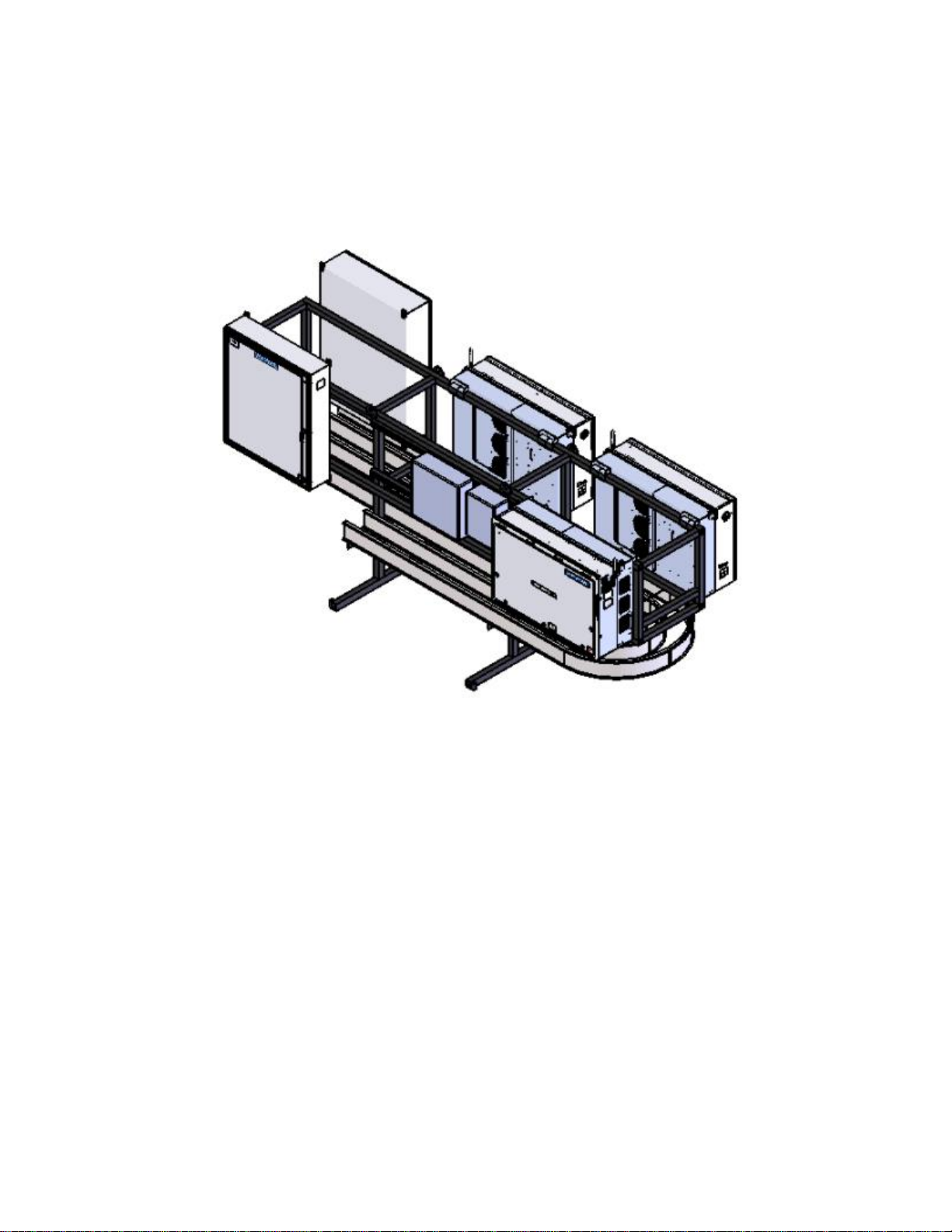
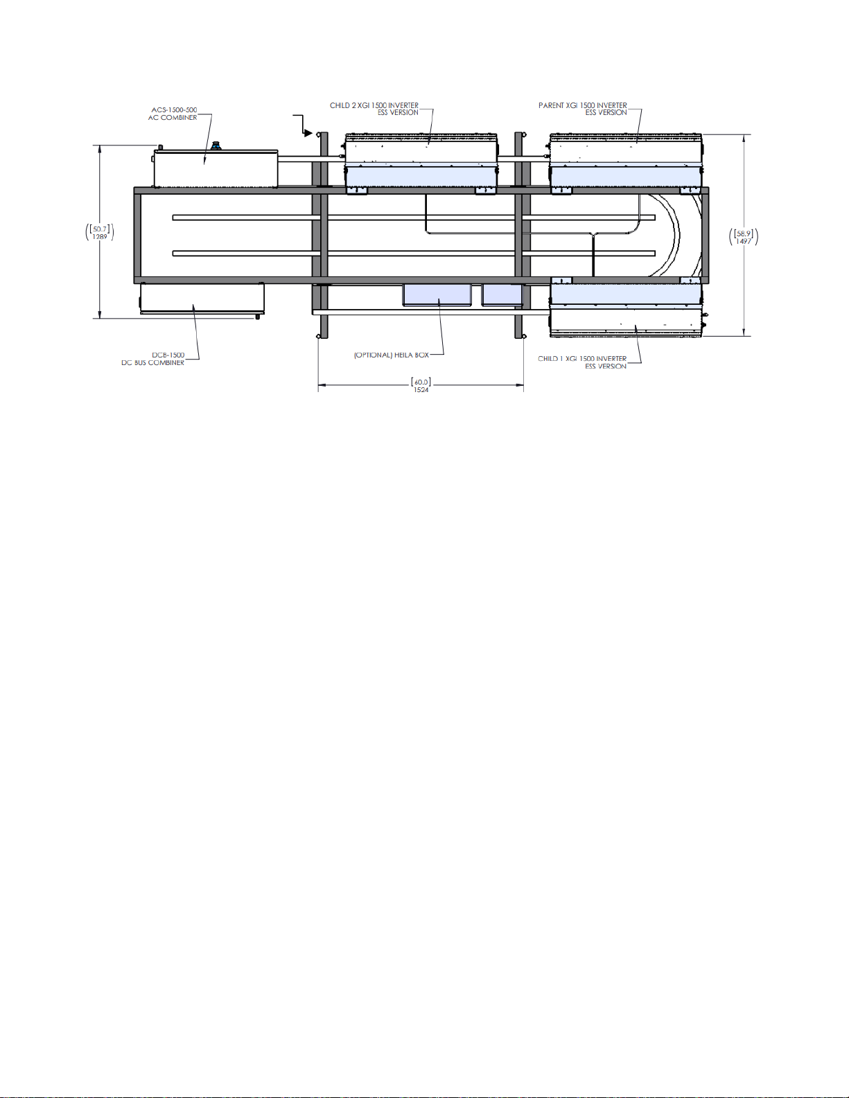
2. SYSTEM OVERVIEW......................................................................................................................... 6
3. INSTALLATION................................................................................................................................. 8
Delivery ................................................................................................................................... 8
Placement and Anchoring........................................................................................................ 8
AC Wiring................................................................................................................................. 9
DC Wiring of the DC Bus De-Combiner................................................................................... 14
3.4.1 Fastening Lugs to the Studs ............................................................................................ 17
Precautions for Aluminum Wire............................................................................................. 19
Conduit Connections.............................................................................................................. 20
Heila PMC Communications (option) ..................................................................................... 21
Connection to the Internet .................................................................................................... 21
4. System Operation ......................................................................................................................... 22
Initial Commissioning Procedure............................................................................................ 22
System OFF Procedure........................................................................................................... 23
System ON Procedure............................................................................................................ 23
System Configuration............................................................................................................. 24
4.4.1 Defining the Maximum and the Minimum Battery Operational Voltage.......................... 24
4.4.2 Constant communication between PMC and inverters ................................................... 24
Control of Active Power......................................................................................................... 25
4.5.1 Active Power Limit.......................................................................................................... 25
4.5.2 Volt-Watt configuration.................................................................................................. 25
4.5.3 Frequency-Watt configuration........................................................................................ 26
Control of Reactive Power ..................................................................................................... 27
4.6.1 Method 1: Volt-VAr configuration................................................................................... 27
4.6.2 Method 2: Constant Power Factor Configuration............................................................ 28
4.6.3 Method 3: Constant Reactive Power configuration......................................................... 28
5. Specifications................................................................................................................................ 29
6. WARRANTY & RMA INSTRUCTIONS............................................................................................... 29
8. APPENDICES.................................................................................................................................. 30

Yaskawa Solectria Solar DOCR-071070 Page 3of 30
1. IMPORTANT SAFETY INSTRUCTIONS
SAVE THESE INSTRUCTIONS
This manual contains important instructions for model:
ACS-500
The SOLECTRIA ACS 500 AC-Coupled Storage System comprises a factory- integrated set of US-
manufactured and factory-integrated components that form the core of the system: 3 XGI 1500
Inverters, DCB1500-500 DC Bus De-Combiner, ACC1500-500 AC Combiner, and the Plant Master
Controller (PMC). The storage system is complete with the addition of customer-selected
battery system with enclosure, safety elements and controls.
This manual provides instructions for the operation of the ACS-500 AC Coupled Storage System.
In addition, please read all instructions and warnings for the associated component equipment
in their respective manuals.
This manual contains important instructions for operation of the ACS-500 AC-Coupled Storage
System. To reduce the risk of electrical shock and to ensure the safe operation of the system,
the following safety symbols are used to indicate dangerous conditions and important safety
instructions.

Yaskawa Solectria Solar DOCR-071070 Page 4of 30
Hazard Symbols
DANGER
Indicates a hazardous situation, which, if not avoided, will result in death or serious injury.
WARNING
Indicates a hazardous situation, which, if not avoided, could result in death or serious injury.
CAUTION
Indicates a hazardous situation, which, if not avoided, could result in minor or moderate injury.
NOTICE!
Indicates a hazardous condition, which, if not avoided, could result in property damage.
INFO ✔
Indicates important supplementary information to use the product effectively.

Yaskawa Solectria Solar DOCR-071070 Page 5of 30
Symbols on Labels
Table 1-1 Explanation of Symbols on Labels
SYMBOL
DESCRIPTION
DC Signal
AC Signal
Equipment Ground
Phase
Off
On
Positive Connection Point Symbol
Negative Connection Point Symbol
Refer to Operating Instructions
Instructions for Qualified Personnel Only
Caution: Risk of Electric Shock
Do not remove cover until 5 minutes after disconnecting all supply sources
Caution: Risk of Electric Shock
Timed Discharge
Caution: Hot Surface
Do Not Touch
Warning: Hazardous voltage area under plastic cover. Do not open fuse holders
under load. Proper PPE must be used while accessing fuses. For continued
protection against risk of fire, replace only with same make and type of fuse.
Information: For more information, please see the installation and operations
manual

Yaskawa Solectria Solar DOCR-071070 Page 6of 30
2. SYSTEM OVERVIEW
Figure 2-1 ACS-500 System Overview
The ACS-500 system is a redundant, modular energy storage solution that can be AC coupled with other
generators, such as PV or wind. The ACS-500 system comes mounted on a rack and pre-wired from the
factory. The ACS-500 can input or output 500kW and absorb or supply 300kVAr in up to 40C ambient
temperature, controlled through the pre-programmed Plant Master Controller. It can be paired with any
battery type with an equal DC voltage window. Please contact Yaskawa Solectria Solar application
engineering to verify that the voltage window of your battery and that of the ACS-500 match.
The ACS-500 system comprises 4 parts:
DC Bus De-Combiner
AC Combiner
Heila PMC (optional)
Three (3) XGI 1500–166/166-3S 166kW storage-ready inverters

Yaskawa Solectria Solar DOCR-071070 Page 7of 30
Figure 2-2 ACS-500 System Components
The customer connects the positive and negative connection of the battery system to the common bus
bars in the DC Bus De-Combiner. The DC Bus De-Combiner connects the DC to the three inverters with
the appropriate fusing. See the Chapter on DC wiring for more details.
The AC Combiner connects the AC output of the three inverters together with the appropriate fusing.
The customer connects the grounded low-voltage side of the MV transformer to bus bars in the AC
combiner. See the Chapter on AC wiring for more details.
The Heila Edge PMC controls the flow of active and reactive power through the three inverters and
monitors the state of charge (SOC) of the battery through MODBUS TCP/IP messaging. The Heila Edge
PMC draws its supply power from a 346V/120V single phase transformer and is protected by a UPS, to
be able to communicate with the ACS-500 system and the battery in case of a power outage. For more
information consult the Heila Edge PMC manual and the Chapter on Communications.
The three Solectria XGI 1500-166/166-3S inverters control the second-to-second conversion of DC power
to AC power and vice-versa. They are connected in a parent-child topology though CAN bus, where the
children follow the parent’s set points instantaneously. The system is arranged in a fully redundant
fashion; when one inverter encounters a problem the two others continue operating and take over its
load, until a repair has taken place.
ANCHOR HOLE 4X

Yaskawa Solectria Solar DOCR-071070 Page 8of 30
3. INSTALLATION
Delivery
Check for Damage: Yaskawa Solectria Solar thoroughly inspects and rigorously tests all rack-mounted
components in the ACS-500 AC-Coupled Storage System before shipment. On rare occasions damage
may occur during shipping. Upon receipt of the ACS-500 system, please do the following:
Inspect all ACS-500 system as received, pre-mounted and pre-wired on the rack.
If damage is observed, take digital photos to document the damage and immediately report the
damage to the shipping company.
If the recipient has any question about the potential shipping damage, contact Yaskawa Solectria
Solar (see Section 6 for contact information).
If Yaskawa Solectria Solar determines that any component of the ACS-500 needs to be returned,
obtain an RMA number from Yaskawa Solectria Solar and instructions for returning the unit.
Placement and Anchoring
To anchor the ACS-500 to a concrete pad, secure anchor bolts at the four anchoring provisions located
at the ends of the horizontal support bars. These anchor points have an internal diameter opening of 1”
(see Figure 2-2 ACS-500 System Components).Failure to secure the rack with anchoring bolts will render
the warranty of the ACS-500 void.
Please refer to the following installation diagram for anchoring point locations and customer conduit
locations:
Figure 3-1: Installation Diagram showing Areas Available (shaded) for Conduit

Yaskawa Solectria Solar DOCR-071070 Page 9of 30
AC Wiring
All AC Wiring is completed at the factory, within the ACC-1500-500 AC combiner box that is pre-mounted
to the ACS-500 rack.
STEP 1: Confirm that all wiring and associated components are de-energized
Confirm that the AC switch on the AC Combiner is in the OFF position.
Confirm that the AC switch on the XGI 1500 inverters (on the rack with other equipment in the
ACS-500 AC-Coupled Storage system) are in the OFF position (Fig 4.1).
Confirm there is no voltage at the terminals for the XGI 1500 inverters’ AC output conductors in
the ACC1500-500 AC Combiner.
Figure 3-2: Rotate the XGI 1500 Inverter AC Disconnect to the “Off” position
DANGER
Electric Shock Hazard: Components with hazardous voltage and energy will electrocute operator.
Operator shall avoid touching live components with hazardous voltage and energy. Verify the absence
of voltage using an appropriately rated multimeter.
STEP 2: Prepare the Enclosure for Conduits
Note the target area for conduit connections for the combined AC Output Circuit, in the conduit
installation diagram. Only the shaded area indicated should be used.
Add the holes for the conduit and fittings to the shaded area of the bottom of the AC combiner.
The AC combiner provides adequate space for 2” – 3” conduits for the 3-phase 600VAC
conductors.
Remove all metal shavings and debris from the inside of the AC Combiner.

Yaskawa Solectria Solar DOCR-071070 Page 10 of 30
WARNING
Remove all metal shavings and debris from the inside of the ACC1500-500 AC Combiner enclosure.
Figure 3-3: Interior of the ACC1500-500 AC Combiner
Figure 3-4 Bottom of the ACC1500-500 AC Combiner Showing Area Available for Conduit (shaded)
200A 600VAC Fuses, TYPE J, for ΦA,
Φb, Φc, from 3 inverters
ϕ
A
ϕ
B
ϕ
C
HINGED
COVER
600A 600VAC FUSES, TYPE J, for
ΦA, Φb, Φc, combined output
from 3 inverters
DUAL BARREL LUGS for FIELD-WIRED
OUTPUT,
3-PH 600VAC, included
EQUIPMENT GROUND TERMINAL
AUX POWER, 3A FUSES
346 VAC, to the Heila Edge PMC
600A, 600VAC 3-POLE
DISCONNECT SWITCH

Yaskawa Solectria Solar DOCR-071070 Page 11 of 30
STEP 3: AC Output Circuit Connections
CAUTION
Do not attempt to make connections to the ACC-1500-500 AC Combiner if not qualified for
electrical work.
See NEC Articles 310 and 690 for proper conductor sizing. The phase lugs are shown in Figure 3-5 and
their specifications in Table 3-2.
Figure 3-5: Phase Lugs (one per phase)
Table 3-1 Phase Lug Specifications
PHASE LUGS SPECIFICATIONS
CONDUCTOR
COMPATIBILITY
6AWG –350kcmil
Copper and Aluminum
CONDUCTOR TYPE
2-Barrel
TEMPERATURE RATING
90C
TORQUE
350kcmil to > 2 AWG: 375 in-lb
6 AWG to ≤ 2 AWG: 275 in-lb
Follow these steps when making conductor connections in the AC Combiner:
Verify absence of voltage on all conductors.
Run the AC Output Circuit conductors into the AC Combiner through appropriate conduit and
fittings.
Connect the phase conductors to the lugs and apply torque per the specifications in Table 3-2.
Connect equipment ground conductors to the equipment ground terminals.

Yaskawa Solectria Solar DOCR-071070 Page 12 of 30
STEP 4: Equipment Ground Wire Connections
Figure 3-6: Equipment Ground Bar
Terminals are provided in the Combiner for all Equipment Grounding Conductors (EGCs). Torque each
EGC per the specifications in the Table below.
Table 3-2: Ground Bar Specifications
GROUND BAR SPECIFICATIONS
POSITIONS
12
CONDUCTOR COMPATIBILITY
12 (Al) / 14 (Cu) AWG –4 AWG
TEMPERATURE RATING
90C
TORQUE
20 in-lb, flat-head screwdriver
STEP 5: Final Steps
INFO ✔
Verify the proper phase sequence of each conductor. The ACS 500 System will not turn on if the phases
are in reverse sequence.
Check the AC Combiner for tools and debris; ensure that the unit is clean and orderly.
Verify that all connections meet the requirements of this User’s Manual.
Secure the ACC-1500-500 AC Combiner cover, ensuring that all ¼-turn fasteners are secured.
Consult the startup and commissioning procedures for the ACS-500 AC-Coupled Energy Storage
system before energizing.

Yaskawa Solectria Solar DOCR-071070 Page 13 of 30
WARNING
Do not operate the disconnect handle switch with the AC Combiner door open.
Figure 3-7 Switch Handle Positions for OFF (left) and ON (right)
The ACC-1500-500 AC Combiner contains a user-operable AC disconnect switch. When this disconnect
switch handle is in the OFF position, the circuit is open between the input Inverter AC Output Circuit
conductors and the combined AC Output Circuit conductors. The disconnect handle can be locked in the
OFF position with user-supplied safety locks. The plastic tab on the face of the disconnect handle can be
lifted to reveal the locking provisions.
The disconnect switch is rated for 600A, is fully load-break rated and can be safely operated under
normal operating conditions when installation is per this User’s Manual and all warnings and ratings are
observed.
90°
ON
OFF
OFFF
ON

Yaskawa Solectria Solar DOCR-071070 Page 14 of 30
DC Wiring of the DC Bus De-Combiner
All DC wiring from the DC Bus De-Combiner to the three XGI 1500 Inverters is completed in the factory.
The De-Combiner DC bus fusing distributes 3 separate DC outputs to the 3 inverters on the ACS-500
rack.
The DCB-1500-500-3X166 DC Bus De-Combiner (see Figure 3-8) performs the following basic functions:
(1) Storage Subsystem Connections:
Termination for conductors from the Storage Subsystem
(2) Solectria XGI 1500 Inverter Connections:
Connection from the main DC bus to overcurrent protection sized for the three XGI
1500 inverters.
Stud terminals for the factory-wired connections from the De-Combiner to the XGI
1500 inverters.

Yaskawa Solectria Solar DOCR-071070 Page 15 of 30
Figure 3-8 The DCB-1500-500-3X166 DC De-Combiner Components
STEP 1: Disconnect all Equipment before Wiring to the De-Combiner
The De-Combiner arrives installed on the rack, with pre-wired conductors to the XGI 1500 inverters on
the rack. The only wiring to complete are the conductors between the De-Combiner and the Battery
Storage System. Before beginning to run these conductors:
Open the DC switch or breaker(s) located with the Battery Subsystem, to de-energize the field-
wiring terminals at the Battery Subsystem
Open the AC switch on all XGI 1500 inverters, to de-energize the factory-wired conductors
between the XGI 1500 inverters and the De-Combiner.
STEP 2: Prepare the Enclosure for Conduits
1. Note the target area for conduit connections for the Battery Subsystem conductors on the
bottom face of the De-Combiner, as shown in Figure 3-9.
2. Add the necessary holes for the conduits for the Battery Subsystem conductor entries.
3. Be sure to remove any metal shavings and debris from the inside of the De-Combiner.
Studs for 2 Negative
conductors, with lugs,
from Battery
Subsystem
Studs for 2 Positive
conductors, with lugs,
from Battery
Subsystem

Yaskawa Solectria Solar DOCR-071070 Page 16 of 30
Figure 3-9: Bottom face of the De-Combiner, showing the area for conduit connections for the Battery Subsystem.
STEP 3: Battery Subsystem Conductor Termination
CAUTION
Do not attempt to make connections to the DC De-Combiner if not qualified for electrical
work.
Compression lugs are NOT provided with the DC De-Combiners. Lugs must conform to the specifications
below:
Table 3-3 Lug Specification
LUG TYPE
PLATING &
MATERIAL
MAX. TONGUE
WIDTH
STUD SIZE
TEMP
RATING
TWO-HOLE
1.75 IN. C-C SPACING
Tin Plated
Cu
2.1 in.
M10 (3/8 in.)
90C
MAXIMUM DISTANCE FROM FURTHEST HOLE CENTER TO END OF LUG IS 65MM.
FIGURE 3-10 DC LUG DETAIL
≤ 65 mm

Yaskawa Solectria Solar DOCR-071070 Page 17 of 30
Table 3-4 Conductors
The DCB-1500-500-3X166 has a maximum DC operating current of 593A (197.7A per inverter).
3.4.1 Fastening Lugs to the Studs
Arrange the fasteners as shown in the image: flat washer, lock washer, and nut.
Figure 3-11: DC lug hardware stack mounting detail
Table 3-5: Required DC lug fastening hardware
FASTENERS
(CUSTOMER
SUPPLIED)
4pcs 10mm SS Hex Nut
4pcs 10mm SS Lock washer
4pcs 10mm SS Flat Washer
Torque: 178 in-lb (20 Nm)
STEP 4: Equipment Ground Wiring
Three dual-position mechanical lugs are provided in the De-Combiner for Equipment
Grounding Conductors (EGCs) associated with the Battery Subsystem and XGI 1500 inverters.
CONDUCTOR REQUIREMENTS
MAX ALLOWABLE CONDUCTOR SIZE
Cu or Al, 90C temp rating
1 conductor at 600 kcmil
CONDUCTORS PER LUG
1
10mm SS Hex Nut
10mm SS Lock washer
10mm SS
Flat Washer

Yaskawa Solectria Solar DOCR-071070 Page 18 of 30
INFO ✔
The De-Combiner comes from the factory with the XGI 1500 inverters’ Equipment Ground Conductors
pre-wired to the ground lugs. Torque each EGC per the specifications below.
Table 3-6: Equipment Grounding Lug
EQUIPMENT GROUND LUG (3X)
CU OR AL CONDUCTORS
MIN: 14 AWG
MAX: 2/0 AWG
90C TEMPERATURE RATED
TORQUE TO 20 IN-LB
STEP 5: Final Steps
CAUTION
Verify the proper polarity of each conductor. Polarity reversal can lead to dangerous conditions
capable of harming personnel and equipment.
INFO ✔
Check the De-Combiner for tools and debris; ensure that the unit is clean and orderly.
1. Verify that all connections meet the requirements of this User’s Manual.
2. Secure the De-Combiner cover, ensuring that all fasteners are in place.
3. Consult the startup and commissioning procedures for the system before energizing.

Yaskawa Solectria Solar DOCR-071070 Page 19 of 30
Precautions for Aluminum Wire
INFO ✔
Aluminum oxidizes quickly when exposed to the atmosphere. An oxidized layer is a poor conductor
that could lead to thermal issues, production loss, or damage to the De-Combiner.
When using aluminum conductors on the AC or DC side of the ACS-500, follow these steps to prepare
the conductors.
1. Prepare one wire at a time.
2. Remove the appropriate insulation from the wire.
3. Using a wire brush, remove the oxidized outer layer from the aluminum conductors.
4. Immediately apply a neutral dielectric grease, such as Ideal NOALOX®anti-oxidant
compound, and connect the aluminum cable to the terminal.
5. If the connection is not made within 30 seconds of applying the compound, repeat this
process, as an oxidized layer may have formed on the conductor.

Yaskawa Solectria Solar DOCR-071070 Page 20 of 30
Conduit Connections
NOTICE!
Conduits connected to an outdoor enclosure can introduce water vapor into the enclosure and lead
to the formation of condensation inside. Failure to follow these guidelines can result in water
intrusion into the unit through the conduit connections and may void the warranty.
Follow these instructions and best practices when securing conduits to the DC De-Combiner and the AC
Combiner.
1. Use UL514B certified water-tight conduit fittings and proper installation methods to provide a
water-tight connection that will maintain the rating of the enclosure.
2. Use an appropriately rated sealant and seal the conduits fully to prevent the exchange of air
between the conduit and the enclosure. Sealing the conduit will help prevent condensation in
the enclosure.
Table of contents
Other YASKAWA Storage manuals