ENGLISH PAGE 7
DESIGN
This section provides information on how to connect your A701 to analog and digital audio sources, analog and digital
video sources and speakers.
[ ]BOX
[ ]BOX [ ]BOX
[ ]BOX
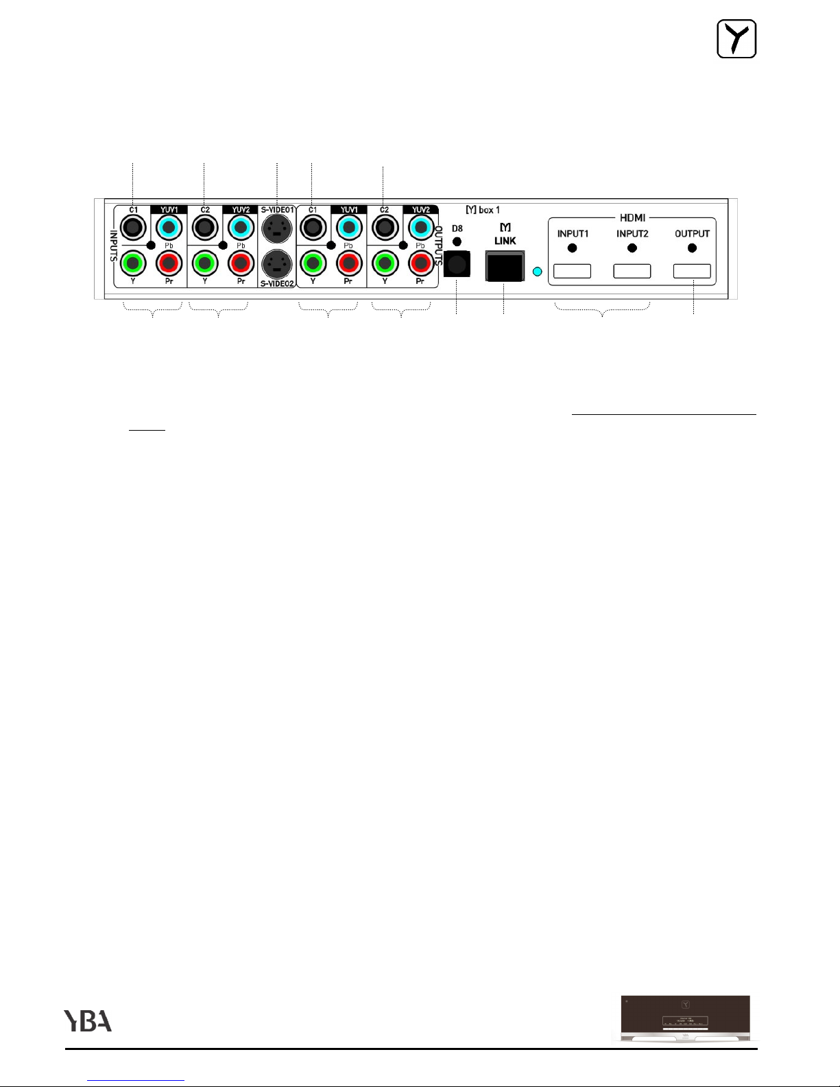
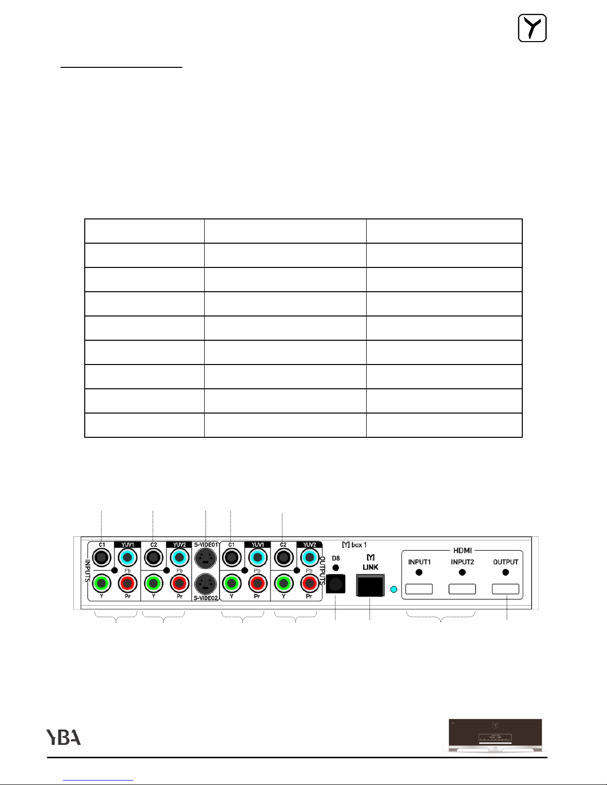
Connect one end of provided [ ]link cable to the [ ]link input on your [ ]box. Connect the other end of the cable to the
[ ]link input of your A701.
Note :
Note :Note :
Note : If you need a longer [ ]link cable, you may replace it by a similar Cat. 5E
Cat. 5E Cat. 5E
Cat. 5E Ethernet straight cable without
exceeding 30 ft (10 m).
AUDIO INPUTS
AUDIO INPUTSAUDIO INPUTS
AUDIO INPUTS
Note :
Note :Note :
Note :
- To get the best sound performances from your audio system, we highly recommend to use the digital
To get the best sound performances from your audio system, we highly recommend to use the digital To get the best sound performances from your audio system, we highly recommend to use the digital
To get the best sound performances from your audio system, we highly recommend to use the digital
output of your source component instead of its analog outputs.
output of your source component instead of its analog outputs. output of your source component instead of its analog outputs.
output of your source component instead of its analog outputs.
- If you own a SACD, a Blue Ray or an HD
If you own a SACD, a Blue Ray or an HDIf you own a SACD, a Blue Ray or an HD
If you own a SACD, a Blue Ray or an HD-
--
-DVD player you can connect its digital output to any digital input
DVD player you can connect its digital output to any digital input DVD player you can connect its digital output to any digital input
DVD player you can connect its digital output to any digital input
of your A701 to enjoy any of your CD or DVD. However, some audio formats such as DSD (on SACD discs),
of your A701 to enjoy any of your CD or DVD. However, some audio formats such as DSD (on SACD discs), of your A701 to enjoy any of your CD or DVD. However, some audio formats such as DSD (on SACD discs),
of your A701 to enjoy any of your CD or DVD. However, some audio formats such as DSD (on SACD discs),
Dolby True HD or DTS HD
Dolby True HD or DTS HDDolby True HD or DTS HD
Dolby True HD or DTS HD-
--
-Master (on some Blue Ray or HD
Master (on some Blue Ray or HDMaster (on some Blue Ray or HD
Master (on some Blue Ray or HD-
--
-DVD discs) can only be decoded and
DVD discs) can only be decoded and DVD discs) can only be decoded and
DVD discs) can only be decoded and
converted by your player. Thus you must also connect your player 5.1 (or 7.1 for some Blue Ray or HD
converted by your player. Thus you must also connect your player 5.1 (or 7.1 for some Blue Ray or HDconverted by your player. Thus you must also connect your player 5.1 (or 7.1 for some Blue Ray or HD
converted by your player. Thus you must also connect your player 5.1 (or 7.1 for some Blue Ray or HD-
--
-
DVD players) analog outputs to the 5.1 (or 7.1) inputs of your A701. This connection will provide full
DVD players) analog outputs to the 5.1 (or 7.1) inputs of your A701. This connection will provide fullDVD players) analog outputs to the 5.1 (or 7.1) inputs of your A701. This connection will provide full
DVD players) analog outputs to the 5.1 (or 7.1) inputs of your A701. This connection will provide full-
--
-
bandwidth reproduction of the audio signal originating from your high definition player allowing you to
bandwidth reproduction of the audio signal originating from your high definition player allowing you to bandwidth reproduction of the audio signal originating from your high definition player allowing you to
bandwidth reproduction of the audio signal originating from your high definition player allowing you to
enjoy the full performances of next generation audio formats.
enjoy the full performances of next generation audio formats.enjoy the full performances of next generation audio formats.
enjoy the full performances of next generation audio formats.
-
Zone 2 users only
Zone 2 users only Zone 2 users only
Zone 2 users only
: For source devices that are equipped with both digital and analog outputs, the digital
: For source devices that are equipped with both digital and analog outputs, the digital : For source devices that are equipped with both digital and analog outputs, the digital
: For source devices that are equipped with both digital and analog outputs, the digital
output should be connected for listening in the main room whereas the analog outputs should be
output should be connected for listening in the main room whereas the analog outputs should be output should be connected for listening in the main room whereas the analog outputs should be
output should be connected for listening in the main room whereas the analog outputs should be
connected for listening in zone 2. Please read section dedicated to zone 2 functions on page 46 of this
connected for listening in zone 2. Please read section dedicated to zone 2 functions on page 46 of this connected for listening in zone 2. Please read section dedicated to zone 2 functions on page 46 of this
connected for listening in zone 2. Please read section dedicated to zone 2 functions on page 46 of this
manual for more details.
manual for more details.manual for more details.
manual for more details.
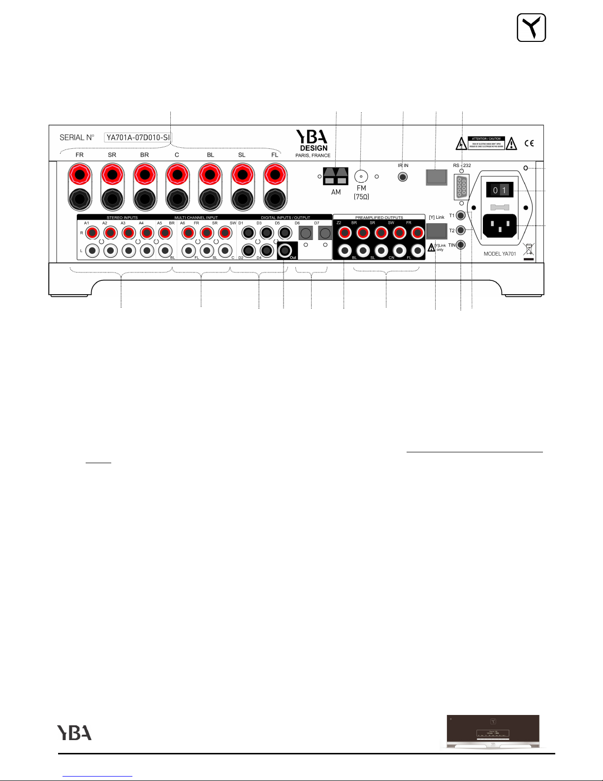
1. Connect the digital audio output of your source components to one of the 8 digital inputs of your A701 (D1 to
D7 on your A701 and D8 on your [ ]box).
2. Connect the stereo analog output of your source to one of the 5 analog inputs of your A701 (A1 to A5).
Connect the right output of your source component to the right input of your A701. Connect the left output of
your source component to the left input of your A701.
2. For multichannel analog source (for example a SACD player), connect the outputs of your source component
to the 5.1 input of your A701 (A6). ou can also connect a 7.1 multichannel device (such as Blue Ray or HD-
DVD player with 7.1 outputs) using the 5.1 input (A6) and the A5 input to handle the 2 additional back channels
(BL and BR). Please review speaker set up section of this manual for more details on how to convert the A5
input to BL and BR input. Note that you can only connect a 7.1 input if you have enabled 7 speakers in your
main room.
YA701 - CONNECTING / AUDIO
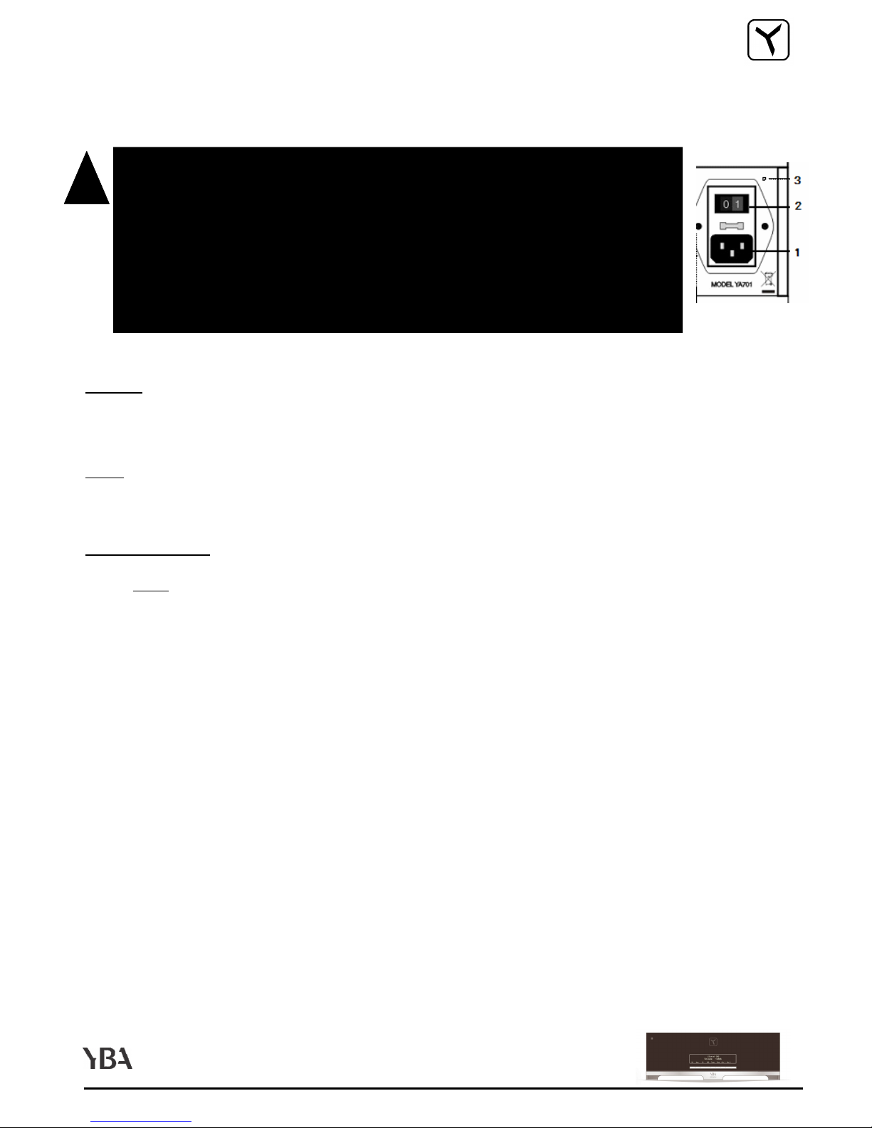
!
!!
!
•
Make sure your A701 is in OFF position : ON/OFF button
Make sure your A701 is in OFF position : ON/OFF button Make sure your A701 is in OFF position : ON/OFF button
Make sure your A701 is in OFF position : ON/OFF button set to OFF and
set to OFF and set to OFF and
set to OFF and
power status led
power status led power status led
power status led not red. If you have any doubt, unplug the AC cable from
not red. If you have any doubt, unplug the AC cable from not red. If you have any doubt, unplug the AC cable from
not red. If you have any doubt, unplug the AC cable from
the power inlet
the power inlet the power inlet
the power inlet .
..
.
•
Make sure all power sources and components are off before connecting or
Make sure all power sources and components are off before connecting or Make sure all power sources and components are off before connecting or
Make sure all power sources and components are off before connecting or
disconnecting any input or output.
disconnecting any input or output.disconnecting any input or output.
disconnecting any input or output.
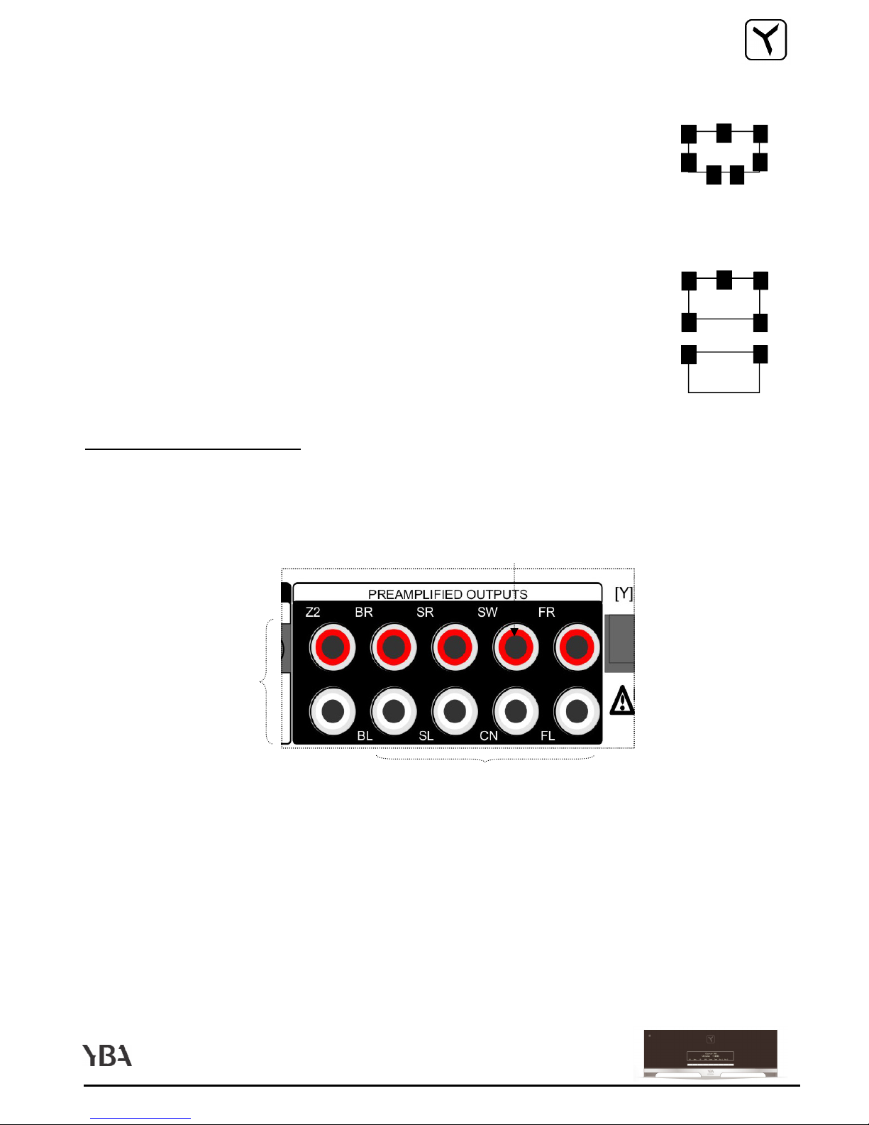
•
Neatly arrange and organize wiring to and from your A701 and to and from
Neatly arrange and organize wiring to and from your A701 and to and from Neatly arrange and organize wiring to and from your A701 and to and from
Neatly arrange and organize wiring to and from your A701 and to and from
your [ ]box and all components. Separate AC wires from audio cables to
your [ ]box and all components. Separate AC wires from audio cables to your [ ]box and all components. Separate AC wires from audio cables to
your [ ]box and all components. Separate AC wires from audio cables to
prevent hum or other unwanted noise from being introduced into the sys-
prevent hum or other unwanted noise from being introduced into the sys-prevent hum or other unwanted noise from being introduced into the sys-
prevent hum or other unwanted noise from being introduced into the sys-
tem.
tem.tem.
tem.