Copyright 2019 EAI All Rights Reserved 6 / 11
Starting angle solution formula:AngleFSA =
End angle solution formula:AngleLSA =
Intermediate angle solution formula:
=
AngleFSA
Rshiftbit (data,1) means shifting the data to the right by one bit. means the
clockwise angle difference from the starting angle (uncorrected value) to the ending angle
(uncorrected value), and LSN represents the number of packet samples in this frame.
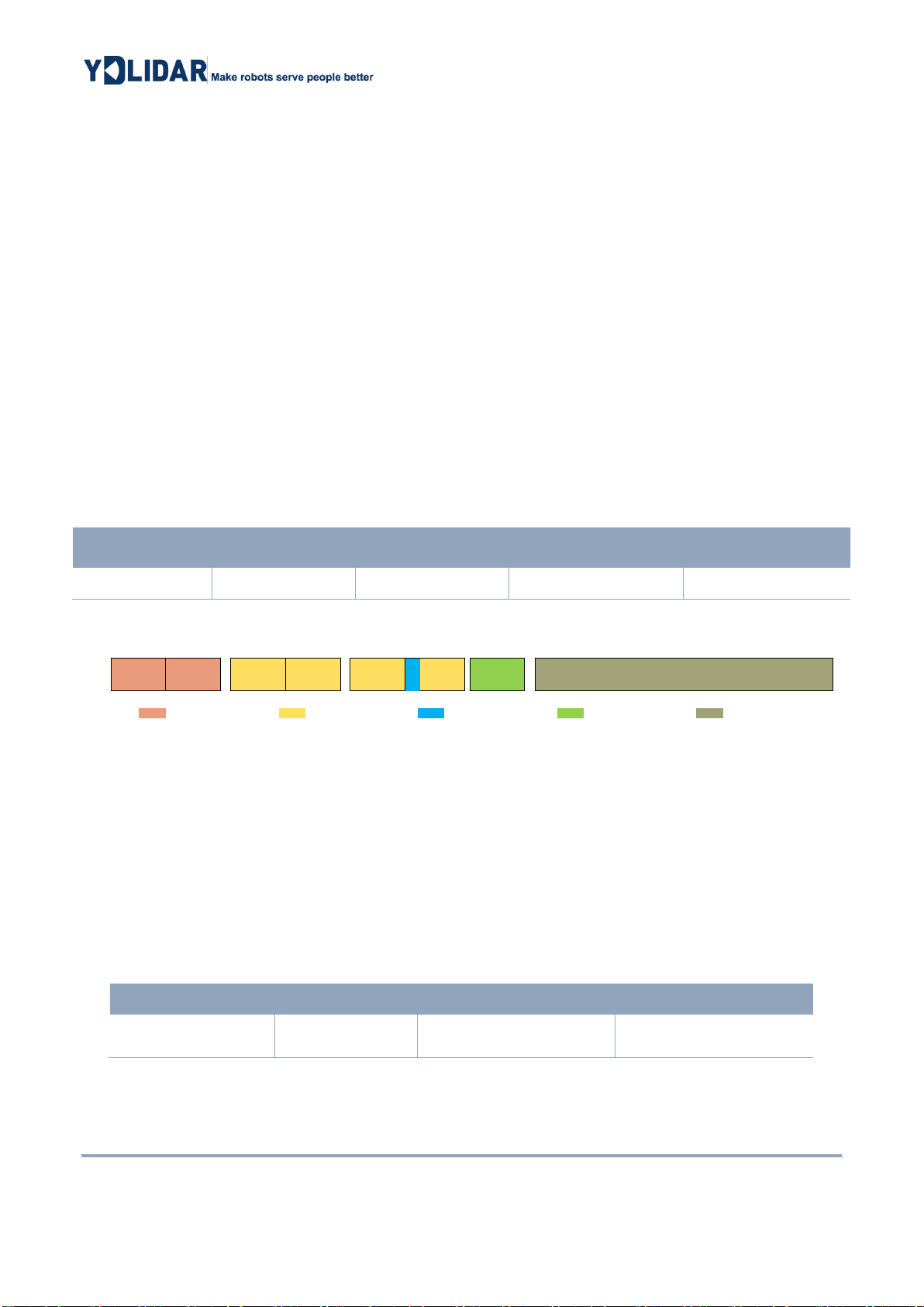
➢Check code parsing:
The check code uses a two-byte exclusive OR to verify the
current data packet. The check code itself does not participate in
XOR operations, and the XOR order is not strictly in byte order.
The XOR sequence is as shown in the figure. Therefore, the
check code solution formula is:
CS=
(Ci) =1,2,…,end
indicates the XOR of the element from subscript 1 to end. However, XOR satisfies the
exchange law, and the actual solution may not need to follow the XOR sequence.
3.2 Stop Command [A5 65]
When the system is in the scanning state, TG Series always sends point cloud data to the
outside. If you need to turn off scanning at this time, you can send this command to stop the system
from scanning. After the stop command is sent, the system will be in the standby state. At this time,
the ranging unit of the device is in the low power mode, and the laser is not lit.
The command is unresponsive, so the system will not respond to any messages after receiving
the command.
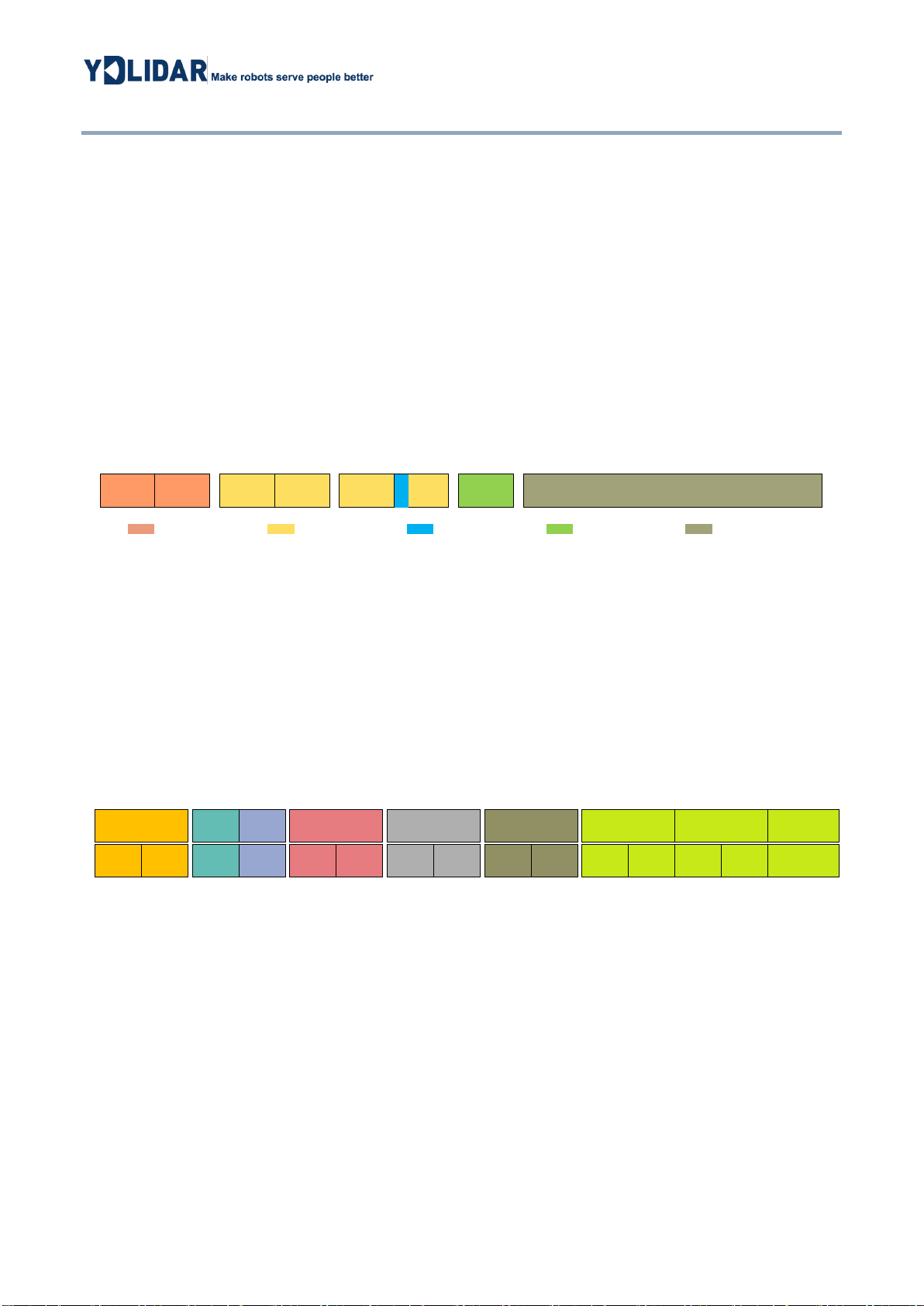
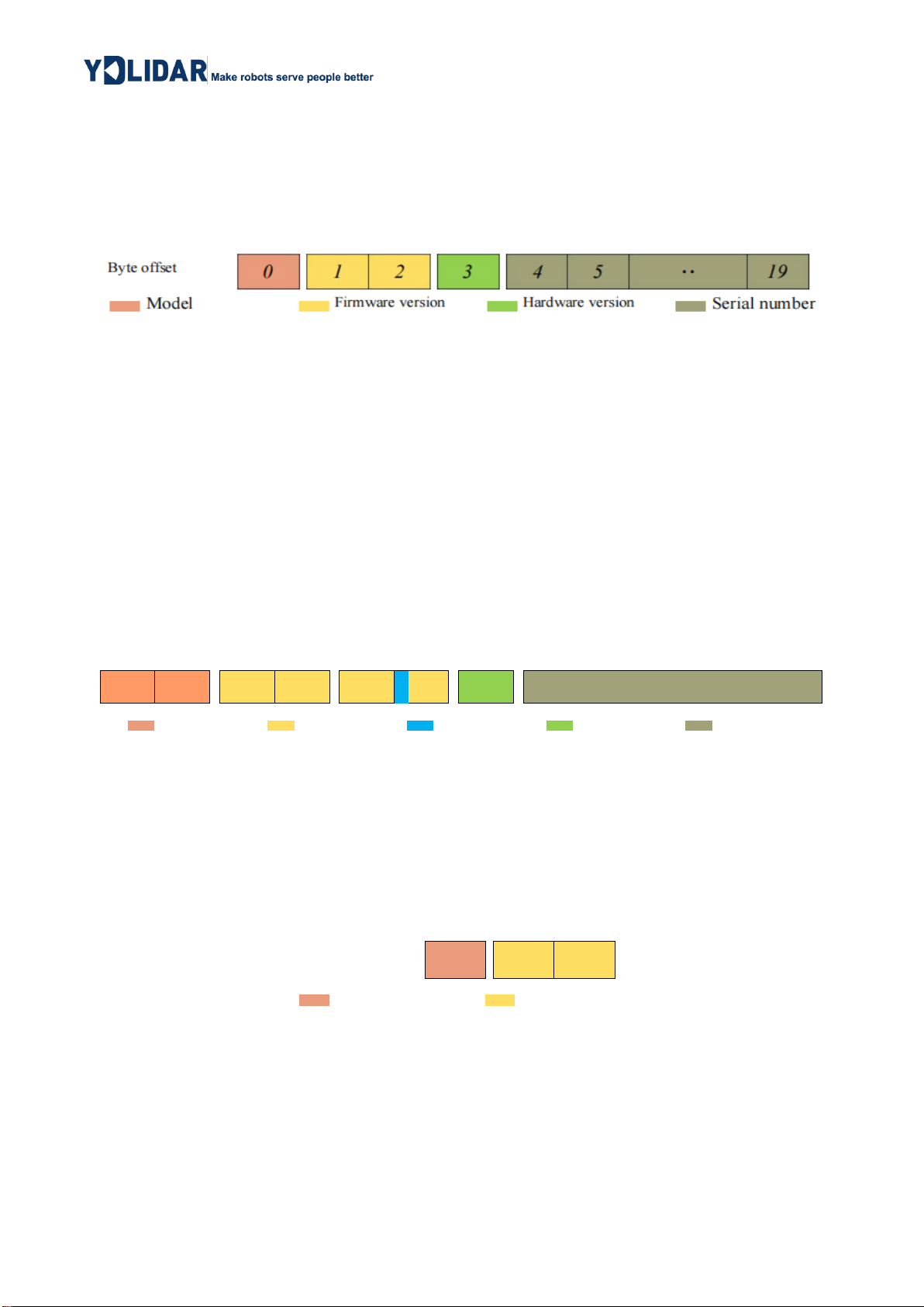
3.3 Device Information [A5 90]
When an external device sends a Get Device Information command to (A5 90), TG Series will
feedback the device's model, firmware version, and hardware version, and the device's factory serial
number. The reply message is:
FIG 9 YDLIDAR TG SERIES DEVICE INFORMATION