YDLIDAR X2 User manual

https://www.facebook.com/ydlidar/
YDLIDAR X2
USER MANUAL
DOC#:01.13. 000102

www.ydlidar.com Copyright 2015-2019 EAI
1/12
CONTENTS
WINDOWS USAGE GUIDE..........................................................2
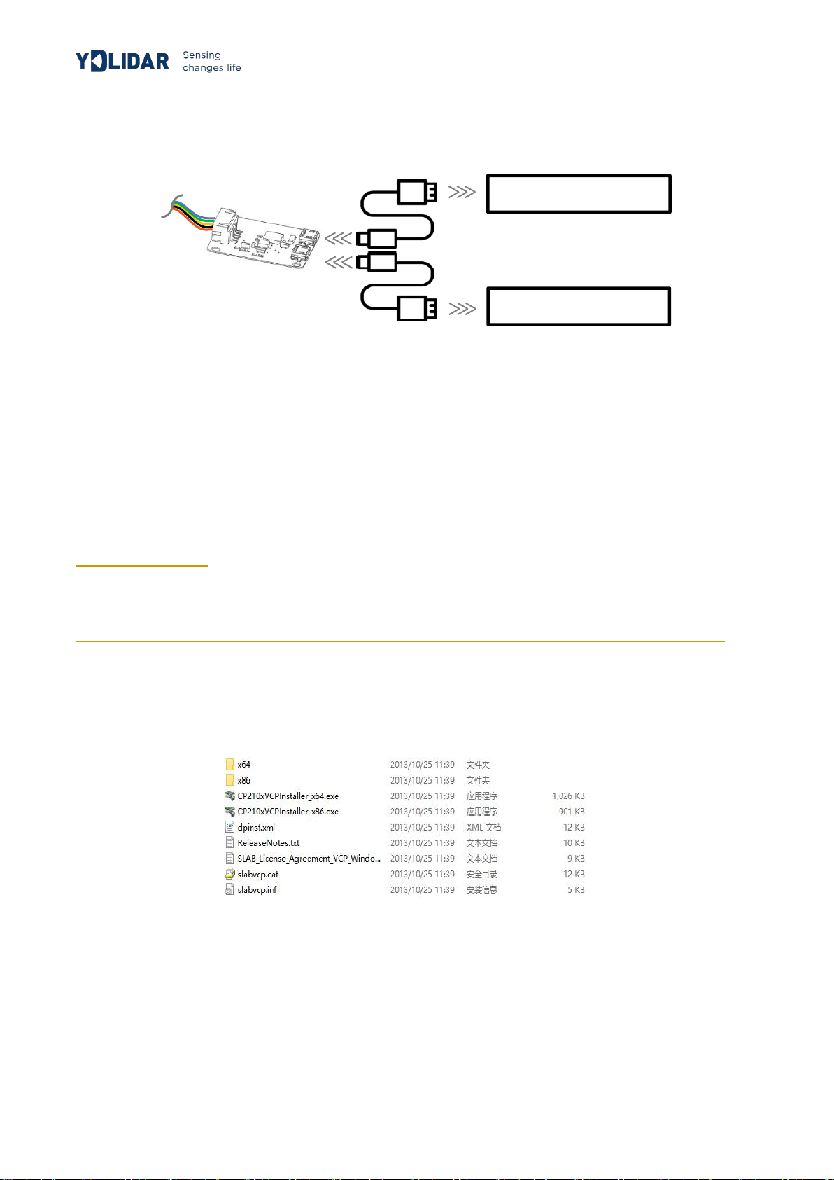
Device connection........................................................................ 2
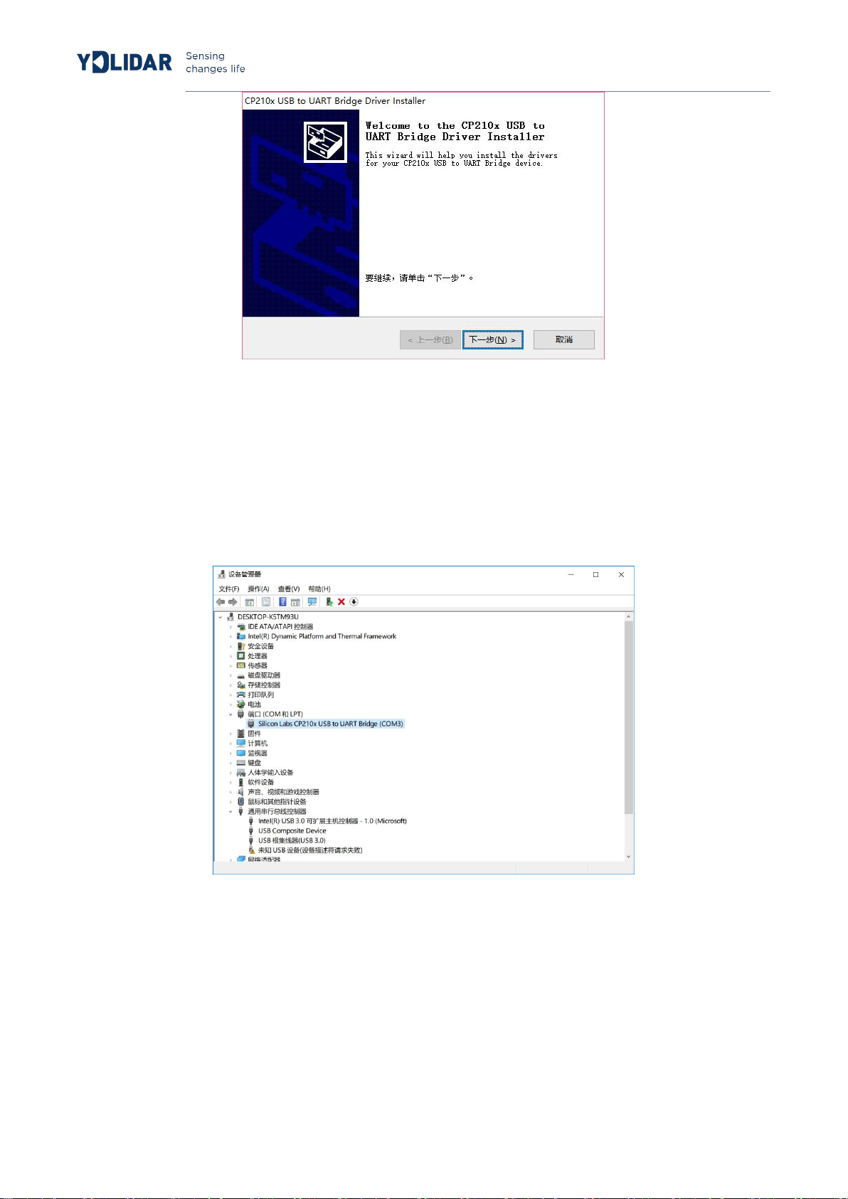
Driver Installation..........................................................................3
Evaluation software......................................................................4
Start scanning.............................................................................6
System settings.......................................................................... 6
Save data.....................................................................................7
Angle calibration.........................................................................7
Firmware upgrade......................................................................8
LINUX ROS OPERATION.............................................................9
Device connection........................................................................ 9
ROS Driver Installation................................................................9
RVIZ installation............................................................................9
RVIZ Check the scan results................................................... 10
Modify the scan angle problem................................................10
Precautions for use...................................................................... 11
Temperature................................................................................11
Ambient lighting.......................................................................... 12
Power demand............................................................................12
Revision.......................................................................................... 12

www.ydlidar.com Copyright 2015-2019 EAI
2/12
WINDOWS USAGE GUIDE
Device connection
When evaluating and developing X2 under windows, you need to interconnect X2
and PC. The specific process is as follows:
FIG 1 YDLIDAR X2 CONNECTION STEP 1
FIG 2 YDLIDAR X2 CONNECTION STEP 2
First connect the adapter board and X2, then connect the USB cable to the USB port of
the adapter board and PC. Note that the Micro interface of the USB cable is connected
to the USB_DATA.After X2 is powered on, it is in idle mode without turning its motor.
The USB interface’s drive current in some development platforms or PCs is weak, so X2
needs a +5V auxiliary power supply to support its normal work.

www.ydlidar.com Copyright 2015-2019 EAI
3/12
5V Power Supply
Development Platform
FIG 3 YDLIDAR X2 AUXILIARY POWER SUPP
Driver Installation
To evaluate and develop the X2 under Windows, please install the serial port driver of the
USB adapter board which adopts CP2102 chip to realize serial port (UART) to USB signal
conversion. Its driver can be downloaded from our official website or downloaded from the
official website of Silicon Labs:
http://ydlidar.com/
http://cn.silabs.com/products/development-tools/software/usb-to-uart-bridge-vcp-drivers
After extracting the driver package, run the CP2102's Windows driver installation file (exe
file under CP210x_VCP_Windows). Please select the 32-bit version (x86) or 64-bit version
(x64) installation program according to the version of the windows operating system.
FIG 4 YDLIDAR X2 DRIVER VERSION SELECTION
Double-click the exe file and follow the prompts to install it

www.ydlidar.com Copyright 2015-2019 EAI
4/12
FIG 5 YDLIDAR X2 DRIVER INSTALLATION
After the installation is complete, right click [My Computer], select [Properties]. Under the
[System] screen, select [Device Manager] in the left menu to enter the device manager.
Expand [Port] to see the serial port name corresponding to the identified USB adapter,
which means the driver is successfully installed.The figure below is COM3. (Note that the
port should be checked if X2 and PC are interconnected)
FIG 6 YDLIDAR X2 DRIVE INSTALLATION
Evaluation software
YDLIDAR provides Point Cloud Viewer, a point cloud data visualization software for X2
real-time scanning. The user can intuitively observe the X2 scan effect picture using this
software. YDLIDAR provides X2 real-time point cloud data and real-time scanning
frequency, and X2 version information can be read at the same time. And can save the
scan data offline to an external file for further analysis.

www.ydlidar.com Copyright 2015-2019 EAI
5/12
Before using YDLIDAR, make sure that the X2 USB adapter board serial port driver is
installed successfully, and check whether the X2 and PC USB ports are successfully
interconnected. Run the evaluation software: PointCloudViewer.exe, select the
corresponding serial port number and model number.
FIG 7 YDLIDAR X2 EVALUATION SOFTWARE
Note: The Lidar does not turn on the heartbeat function by default. This function needs to send
the scan command continuously to make it work normally. If the scanning frequency is stopped,
the Lidar will stop scanning. Currently, G4 and F4 are compatible with this function, and X2 and
X2 are not compatible.
After confirmation,you can see the following screen:
FIG 8 POINTCLOUD VIEWER EVALUATION SOFTWARE STARTUP DISPLAY

www.ydlidar.com Copyright 2015-2019 EAI
6/12
START SCANNING
Click
to start scanning and display the environment point cloud.
Clicking
to stop it,as shown below:
FIGURE 9 LIDAR SCANNING POINT CLOUD DISPLAY10
SYSTEM SETTINGS
Click System Settings and the following settings box will pop up:

www.ydlidar.com Copyright 2015-2019 EAI
7/12
FIGURE 10 CLIENT SETTINGS BOX
As shown in the figure, you can configure and detect the Lidar on this setup page, as well
as Lidar firmware upgrade, client software upgrade, etc.
SAVE DATA
During Lidar scanning,click ,Save the point cloud data as prompted.The system will
save the point cloud information scanned in a circle according to the following format.
FIGURE 11 POINT CLOUD DATA SAVE FORMAT
ANGLE CALIBRATION
During the mechanical assembly of the Lidar, the user may have a deviation in the zero
angle. In this case, the angle calibration function of the client can be used to calibrate
according to actual needs. The specific operations are as follows:
(1) Unlock calibration function
Click the unlock control , the system will pop up the login box, the default password is
ydlidar. The effect of these controls will change after unlocking.
(2) setting the baseline
Click and the system will provide a baseline of the appropriate size as a reference for
the adjustment.
(3) Adjusting the angle
Click to adjust the angle to the appropriate position.
(4) save configuration

www.ydlidar.com Copyright 2015-2019 EAI
8/12
After the adjustment is completed, click the system will automatically save the
calibration parameters, and the calibration will take effect after saving.
(5) Lock calibration function
After the calibration is saved, click again to lock the function to prevent misoperation.
these controls will return to normal functionality after being locked.
FIRMWARE UPGRADE
Click System Settings and select Firmware, as shown in Figure 10. Click to get the latest
firmware. When there is a new version, the user can click on the control to perform a
firmware update on the Lidar.
Note:During the upgrade process,keep the Lidar power supply normal,communication
stable,network steady.Do not plug or unplug the Lidar serial port.
SOFTWARE UPGRADE
The client software will be version-changed and users can update to the latest version for a
better experience.
Click System Settings and select Update, as shown below:
FIGURE 12 SYSTEM UPDATE PAGE

www.ydlidar.com Copyright 2015-2019 EAI
9/12
Select the configuration as shown above, click ‘check for updates’, if there is no new
version, the system will prompt no update; when there is a new version, the software
version information will be filled in the information box, click to update the client software.
LINUX ROS OPERATION
Because there are many Linux versions, this article only uses Ubuntu 16.04, Kinetic
version ROS as an example.
Device connection
Under Linux, the X2 and PC interconnect processes are consistent with those under
Windows. See Device Connection under Window.
ROS Driver Installation
Before doing the following, make sure that the Kinetic version ROS environment
is installed correctly.
(1)Use the command to create the ydlidar_ws workspace and copy the ROS
driver package ydlidar in the X2 package to the ydlidar_ws/src directory. Switch to
the ydlidar_ws workspace and compile again.
$ mkdir -p ~/ydlidar_ws/src
$ cd ~/ydlidar_ws
$ catkin_make
(2)After the compilation is complete, add the ydlidar environment variable to the
~/.bashrc file and make it effective.
$ echo "source ~/ydlidar_ws/devel/setup.bash" >> ~/.bashrc
$ source ~/.bashrc
(3)Add a device alias /dev/ydlidar to the X2 serial port.
$ cd ~/ydlidar_ws/src/ydlidar/startup
$ sudo chmod +x initenv.sh
$ sudo sh initenv.sh
RVIZ installation
(1)Online installation

www.ydlidar.com Copyright 2015-2019 EAI
10 /12
(2)If there is a problem with the installation, update the source cache and reinstall it.
RVIZ Check the scan results
Run the launch file and open rviz to view the X2 scan results, as shown in the following
figure:
FIG13 YDLIDAR X2 RVIZ
Modify the scan angle problem
The scanning data seen by running the launch file is displayed by default with 360-
degree data. To modify the display range, you need to modify the configuration
parameters in the launch file. The specific operation is as follows:
(1)Go to X2.launch's directory and use vim to edit X2.launch. The contents are as
shown in the figure:
$ roscd ydlidar/launch
$ vim lidar.launch
$ sudo apt-get install python-serial ros-kinetic-serial g++ vim \
ros-kinetic-turtlebot-rviz-launchers
$ sudo apt-get update

www.ydlidar.com Copyright 2015-2019 EAI
11 /12
FIG 14 LIDAR.LAUNCH
FILE
(2)The X2 lidar coordinates follow the right-hand rule within ROS, with an angle range
of [-180, 180]. "angle_min" is the start angle, and "angle_max" is the end angle.
The specific scope needs to be modified according to actual use.
0°
90° - 90°
180°/-180°
FIG15 YDLIDAR X2 COORDINATES DEFINITION
PRECAUTIONS FOR USE
Temperature
When the working environment temperature of X2 is too high or too low, it will affect the
accuracy of the distance measuring system. It may also damage the structure of the
scanning system and reduce the life of the X2 lidar. Avoid use in high temperature (>40
degrees Celsius) and low temperature (<0 degrees Celsius) conditions.

www.ydlidar.com Copyright 2015-2019 EAI
12 /12
Ambient lighting
The ideal working environment for the X2 is indoor, indoor lighting (including no light)
will not affect the X2 work. However, avoid using a strong light source (such as a
high-power laser) to directly illuminate the X2's vision system.
If you need to use it outdoors, please avoid that the X2's vision system is directly facing
the sun. This may cause permanent damage to the vision system's sensor chip, thus
invalidating the distance measurement.
Please note that the X2 standard version is subject to interference in outdoor
strong sunlight reflection environments.
Power demand
During the development process, since the drive current of the USB interface of each
platform or the USB interface of the computer may be too low to drive the X2, the external
power supply of the +4V to the X2 needs to be provided through the USB_PWR interface
of the USB interface board. It is not recommended to use mobile phone power bank
because the voltage ripple of some brands of power bank is too large.
REVISION
DATE
VERSION
CONTENTS
2019-04-24
1.0
FIRST WRITTEN
Table of contents
Other YDLIDAR Accessories manuals
Popular Accessories manuals by other brands

Silver Cross
Silver Cross Wave tandem seat manual

Vega
Vega VEGAPULS 66 Foundation Fieldbus Standpipe... Quick setup guide

Stahl
Stahl 8570/12 operating instructions

PR electronic
PR electronic MULTI-SCENT Z 3 operating instructions

Etymotic Research
Etymotic Research ER-15 Quick reference guide

SONBEST
SONBEST SM3810V user manual