Yenen 38100090 Manual

Yenen Shut-off Valve
Installation and Maintenance
Manual
Manual : Shut-off valve installation and maintenance manual
Manual code : SHOF-10-e
Number of pages : 6
ssue date : April 24, 2006
Review Number : 1
Review Number : 14.06.2011

Page 2 of 6
14.06.2011 SHOF-10-e Rev Nr:1
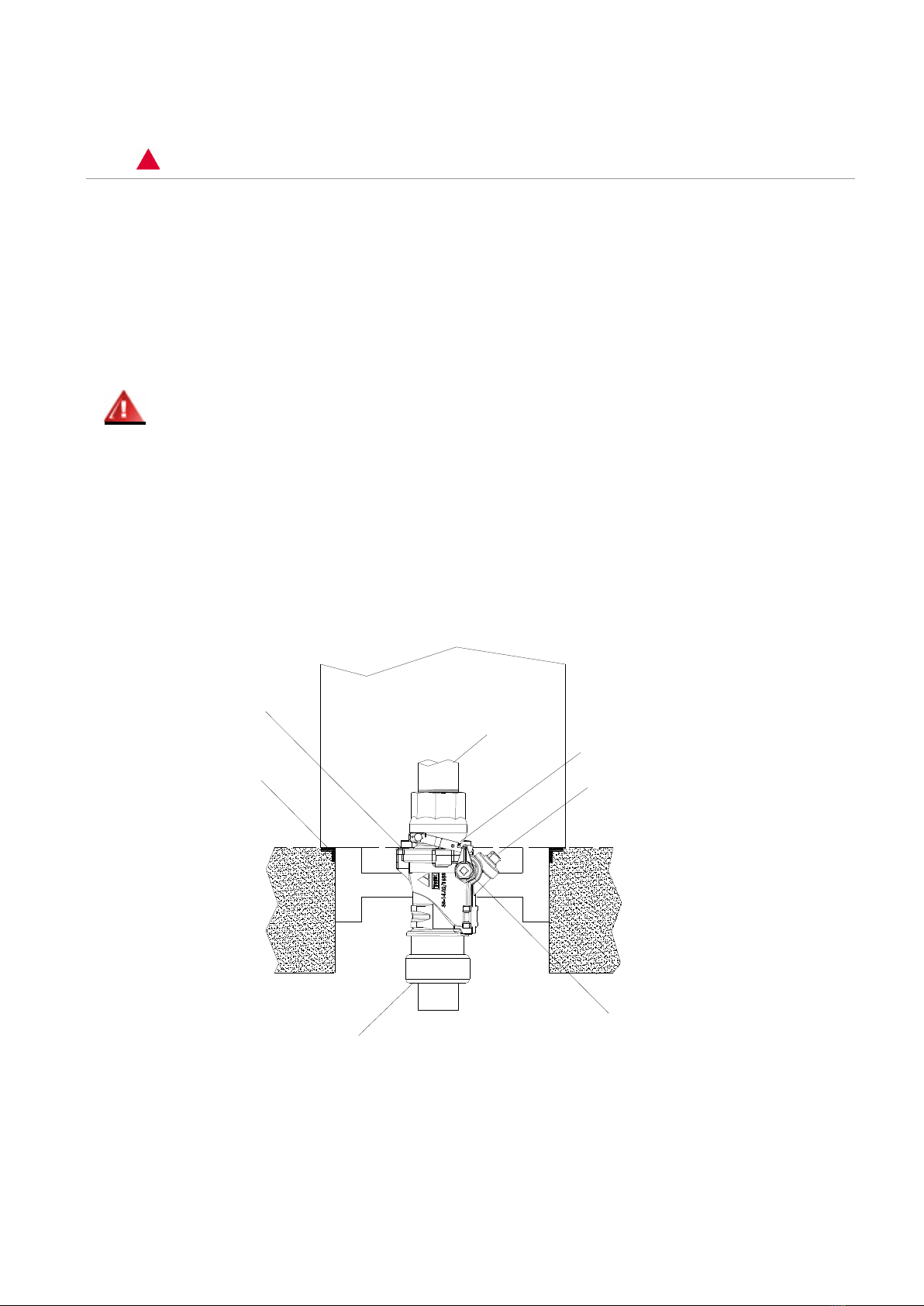
READ THIS MANUAL BE ORE INSTALLING THE SHUT-O VALVE
The proper operation of the shut-off valve depends on correct installation and regular maintenance. Please
read all warnings and follow the instructions carefully. Failure to follow the below precautions and the warning
instructions in this manual will violate all warranties and may result in environmental contamination due to
liquid leakage to the soil, creating hazardous spill conditions. Follow all rules, codes and laws that apply to
your area and installation.
Contact Yenen
Trouble in installing and maintenance of the shut-off valve should be referred to your authorized Yenen dealer
or to Yenen technical support (+90 216 487 5924).
Explanation of symbols
Notice: indicates a special comment or instruction.
Warning: ndicates the presence of a hazard that can cause severe personal injury or property
damage if not observed carefully.
This manual provides instructions and guidelines. The remarks and warnings inform the operator of
the hazards involved in installing and handling shut-off valves. Reading these instructions and
preventing hazardous situations is strictly in the hands of the operator of the equipment. Neglecting
this responsibility is not within the control of Yenen.
No part of Yenen manuals may be reproduced, transmitted, transcribed, stored in a retrieval system, or translated
into any language in any form, by any means, without Yenen’s prior written permission.
Yenen reserves the right to change the specifications of the products described in this manual at any time and
without prior notice.
Yenen cannot and will not be held liable for any damages resulting from the use of this product.
While every effort has been made to ensure that the information in this manual is accurate and complete, Yenen shall
not be held liable for errors contained herein or for incidental or consequential damages in connection of the use of
this manual.
The logo(s) of Yenen Engineering Ltd. are property of Yenen Engineering Ltd.
Yenen Engineering Ltd. is SO9001:2008 certified. For a copy of Yenen’s quality policy and / or Yenen’s HSE policy,
please, visit www.yenen.com or send an email to [email protected] or fax your request to +90 216 487 5986.

Page 3 of 6
14.06.2011 SHOF-10-e Rev Nr:1
SA ETY PRECAUTIONS – INSTALLATION AND MAINTENANCE
Using electrically operated equipment near gasoline or gasoline vapor may result in fire or explosion causing
serious personal injury and/or property damage. ALWAYS disconnect and lock power supply before testing or
servicing the Yenen shut-off valve.
The following instructions are provided to guide you in properly installing and maintaining your Yenen shut-off
valve. Failure to follow these instructions may cause failure of the valve to close in the event of an
emergency, resulting in a hazardous condition. Make sure that all necessary safety precautions have been
taken during installation and maintenance.
The valve body must be firmly anchored to a structural part within the island to ensure breakage at
the shear groove in the event of severe impact. Failure to ascertain a rigid mounting may result in failure of
the valve to close in the event of a severe impact, resulting in excessive loss of product and a hazardous
condition.
The shear groove must be positioned at the same level as the dispenser mounting frame. Failure to install the
shear groove at this level may result in a failure to break-off in the event of severe impact, causing a
hazardous condition.
Dispenser Chassis
Shear Groove
Petroleum Pipe Connection
Dispenser Connection
Test Plug
Soldered Wind Arm
Latch

Page 4 of 6
14.06.2011 SHOF-10-e Rev Nr:1
Attaching valve to riser pipe
1- The riser pipe threads should be coated with a non-hardening, gasoline resistant pipe compound.
Do not use Teflon tape.
2- Thread the valve tightly on the riser pipe wrenching on the main valve body only. Do not wrench
above the shear section as this can result in valve breakage.
3- Maximum torque on pipe threads: 16 kgm.
Attaching outlet valve to fuel dispenser
1- The connecting pipe threads should be coated with a non-hardening, gasoline resistant pipe compound.
Do not use Teflon tape.
2- Hold the valve steady with a wrench on the hex head of the valve. Use a second wrench to tighten the
connection.
3- Maximum torque on pipe threads: 16 kgm.
Manual valve operation
To open the valve, rotate the latch counter-clockwise and hook the latch into the notch on the soldered wind
arm.
To close the valve, unhook the latch from the soldered wind arm, allow the latch to rotate clockwise until it
stops.
Disconnect power to the fuel pump before testing or servicing valves. DO NOT OPEN WHEN P P NG
SYSTEM S UNDER PRESSURE.
Required maintenance
To ensure that the valve is operating freely, it should be manually opened and closed several times, then
reset, at least once a year.
Pressure testing the piping system
This testing is only for the piping system. The tank should be isolated and not subjected to the pressure
used in testing the piping system.
Yenen shut-off valves have a built in 3/8” NPT test plug to permit testing of the piping system for leaks after
installation. Before starting the test, make sure that the pump is turned off. Then manually close all shut-off
valves connected to the same product line, remove the test plug. Attach the gauge and pressurize. t is not
necessary to break any other connections. Maximum recommended test pressure is 4 bars and recommended
test duration is 30 minutes. Local regulations or specifications supersede these recommendations. When
reinstalling the test plug, coat the threads with a non-hardening gasoline resistant pipe compound.

Page 5 of 6
14.06.2011 SHOF-10-e Rev Nr:1
Replacing top shear section
1- Disconnect the power to the dispenser and pump and lock the switch.
2- Close the valve manually and drain the system.
3- Remove the pipe or fitting from the top of the valve. The body does NOT have to be removed.
4- Remove the 3 bolts with a 6 mm Allen and lift damaged top out of body. Remove the o-ring.
5- nstall a new o-ring and then the new top. Replace the 3 bolts and tighten.
6- Reattach the pipe or fitting and test the system for leaks.
7- Connect the power to the dispenser and the pump.
Types of Yenen shut-off valves
Part no Dispenser connection * Pipe connection * Poppet
38100090
1½” Rp
2” BSPT Male
Double
38104090
1½” Rp
1½” BSPT Female
Double
38104190
1 ½” Rp
1½” BSPT Male
Double
38100890
1 ½” Rp
2” BSPT Male
Single
38101390
1 ½” Rp
1 ½” BSPT Female
Single
38101290
1 ½” Rp
1 ½” BSPT Male
Single
* Other types of threaded connections can be specially produced upon request.
Spare part kits
Part no Part name
35011090 Upper body with poppet
35012090 Upper body without poppet

Akşemsettin Mahallesi Tavukçuyolu Sokak No: 23
Sultanbeyli 34925 stanbul / Türkiye
T +90 216 487 5924
+90 216 487 5986
E info@yenen.com
www.yenen.com
This manual suits for next models
7
Table of contents
Popular Control Unit manuals by other brands

Vaisala
Vaisala HUMICAP HMM170 user guide

Mitsubishi
Mitsubishi Melsec-A AJ65SBT user manual

Automationdirect.com
Automationdirect.com Productivity 2000 P2-04DAL-2 manual

Sentiotec
Sentiotec A1 Instructions for installation and use

Afero
Afero ASR-2KL manual

Philips
Philips LBB 2521/10 Installation and user instructions

Eaton
Eaton NH00 installation instructions

Viessmann
Viessmann EM-EA1 extension Installation and service instructions

Curbell
Curbell CSM-BC400 Quick setup guide

SPX
SPX Waukesha Cherry-Burrell W-Series manual

Sierra Wireless
Sierra Wireless MC5720 Hardware integration guide

barfield
barfield DC400 User instruction