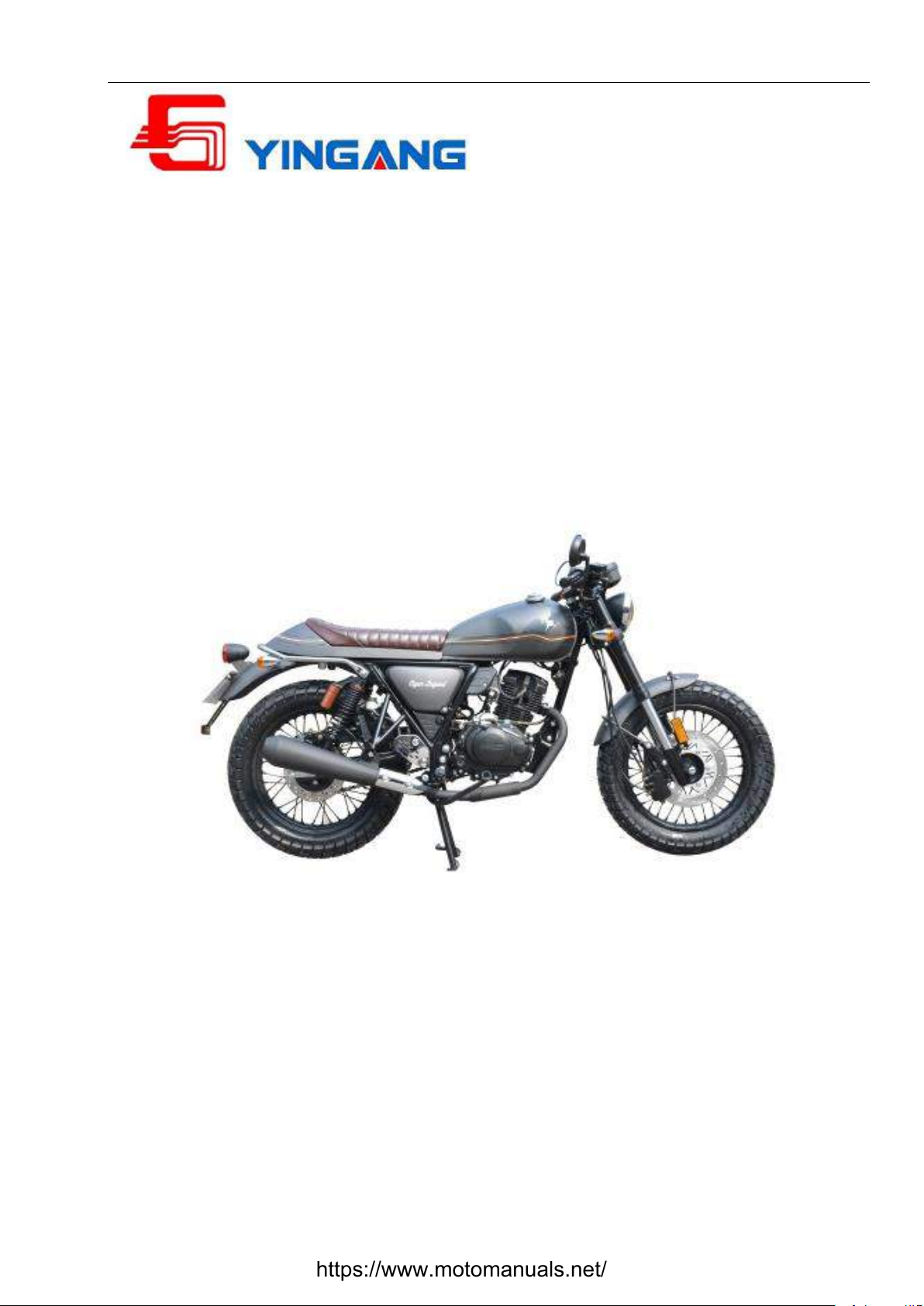
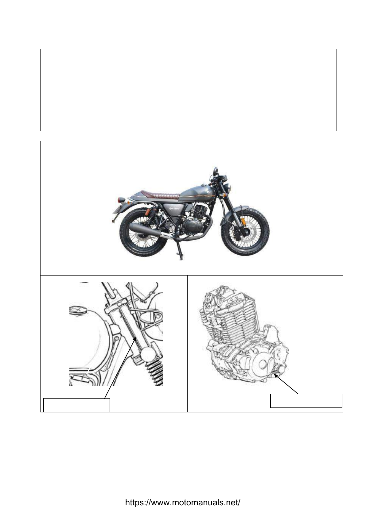
YG125-30A Maintenance Manual Overview
Maintenance Precautions
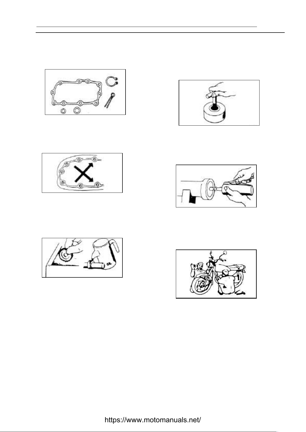
1. Whenever reassembling after being disassembled,
replace new washers, sealing members, etc.
2. While fastening bolts or nuts, proceed in diagonal
crossing sequence to gradually screw down to the
required torque for 2 to 3 tries.
3. After being disassembled, the parts and
components should be cleaned before being
inspected and measured
To clean the spare parts, use only the cleaning
fluid that is incombustible or has high ignition point.
Before reassembling, apply the specified
lubricating oil to the sliding surface of the parts and
components.
After reassembling, check whether all the spare
parts are mounted properly by means of turning,
moving and operating them.
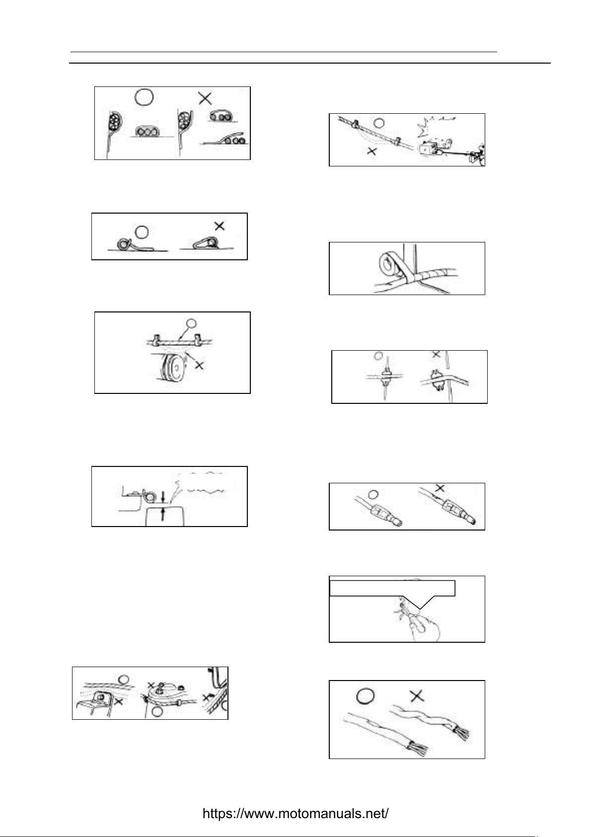
4. To disassemble and assemble a motorcycle,
special service tools (SST) and general-purpose
tools must be used in accordance with relevant
regulations.
5. The specified or equivalent lubricating grease (oil)
must be applied to or refilled into the specified
locations.
6. When 2 or more persons are carrying out the
operation, they shall work with each other and pay
attention to safety.
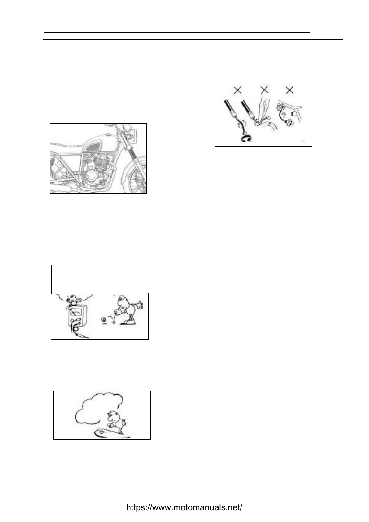
7. Before operating, always remove the negative (-)
end of the battery first and take care to prevent the
wrench or the like from touching the frame. After
operating, reconfirm all the connections, fixings
and junctions. If the battery is already removed,
connect the positive (+) end first.
https://www.motomanuals.net/