YOKOGAWA DPharp EJXC80A User manual

User’s
Manual Diaphragm Seal System
EJXC80A, EJAC80E,
EJXC81A, EJAC81E,
EJXC50A and EJAC50E
IM 01C25W01-01EN
IM 01C25W01-01EN
3rd Edition

Toc-1
IM 01C25W01-01EN
Diaphragm Seal System
EJXC80A, EJAC80E, EJXC81A, EJAC81E, EJXC50A and
EJAC50E
IM 01C25W01-01EN 3rd Edition
3rd Edition: Oct. 2018 (YK)
All Rights Reserved, Copyright © 2016, Yokogawa Electric Corporation
Contents
1. Introduction............................................................................................... 1-1
Regarding This Manual................................................................................................ 1-2
Trademarks ................................................................................................................... 1-3
1.1 Safe Use of This Product ................................................................................. 1-3
1.2 Warranty............................................................................................................. 1-4
2. Handling Cautions.................................................................................... 2-1
2.1 ModelandSpecicationsCheck..................................................................... 2-1
2.2 Unpacking.......................................................................................................... 2-2
2.3 Storage............................................................................................................... 2-2
2.4 Selecting the Installation Location ................................................................ 2-2
2.5 Pressure Connection........................................................................................ 2-2
2.6 WaterproongofCableConduitConnections .............................................. 2-3
2.7 Restrictions on Use of Radio Transceivers ................................................... 2-3
2.8 Insulation Resistance and Dielectric Strength Test...................................... 2-3
3. Component Names .................................................................................. 3-1
4. Installation................................................................................................. 4-1
4.1 Precautions ....................................................................................................... 4-1
4.2 Mounting the Diaphragm Seals (Remote Seals) ........................................... 4-1
4.2.1 Mounting Flush type/Extended type Seals ........................................ 4-1
4.2.2 Mounting Inner Diaphragm Type Seals ............................................. 4-3
4.3 Mounting EJC80and EJC81with Remote Seal ................................ 4-3
4.5 Mounting EJC80with Direct Mount Seal ................................................. 4-5
4.5.1 Mounting ............................................................................................ 4-5
4.5.2 Connecting Impulse Piping to the Transmitter................................... 4-5
4.6 Mounting EJC50with Direct Mount Seal ................................................. 4-6
4.7 Mounting EJC50and EJC80with Hygienic Seal .............................. 4-7
4.7.1 Hygienic Seal (Flush Type) ................................................................ 4-7
4.7.2 Hygienic Seal (Extended Type) ........................................................ 4-7
4.7.3 Tank Spud Mounting Method............................................................. 4-8

Toc-2
IM 01C25W01-01EN
4.8 Rotating Transmitter Section......................................................................... 4-10
4.9 Changing Integral Indicator Direction .......................................................... 4-10
4.10 Mounting the Flushing Connection Ring ..................................................... 4-11
4.10.1 Mounting to Pressure Detector Section........................................... 4-11
4.10.2 Mounting to Process Flange ............................................................ 4-11
4.11 AfxingtheTeonFilm .................................................................................. 4-12
5. Operation................................................................................................... 5-1
5.1 Preparation for Starting Operation ................................................................. 5-1
5.2 Zero Point Adjustment ..................................................................................... 5-3
5.2.1 Zero point adjustment for Absolute Pressure Diaphragm Seal System
........................................................................................................... 5-4
5.3 Starting Operation ............................................................................................ 5-6
5.4 Shutting Down Operation ................................................................................ 5-6
5.5 Venting or Draining Transmitter Pressure-detector Section ....................... 5-6
5.5.1 Draining Condensate ......................................................................... 5-7
5.5.2 Venting Gas........................................................................................ 5-7
5.5.3 Draining Condensate for Flushing Connection Ring or Inner
Diaphragm Type Seal ........................................................................ 5-7
5.5.4 Venting Gas for Flushing Connection Ring or Inner Diaphragm Type
Seal .................................................................................................... 5-8
5.6 Local Parameter Setting................................................................................... 5-8
5.6.1 Local Parameter Setting (LPS) Overview.......................................... 5-9
5.6.2 Activating Local Parameter Setting ................................................. 5-10
5.6.3 Parameter Setting Review ............................................................... 5-10
5.6.4 TagNumberConguration............................................................... 5-11
5.6.5 PressureUnitConguration............................................................. 5-11
5.6.6 PressureLRV/URVConguration ................................................... 5-11
5.6.7 DampingTimeConstantConguration ........................................... 5-12
5.6.8 OutputModeConguration ............................................................. 5-12
5.6.9 DisplayOut1Conguration............................................................. 5-12
5.6.10 Re-range by applying actual pressure (LRV/URV).......................... 5-12
5.6.11 Save or Cancel................................................................................. 5-13
5.6.12 AbortConguration.......................................................................... 5-13
5.6.12.1 AbortConguration(Menu) ............................................ 5-13
5.6.12.2 AbortConguration(Parameter) .................................... 5-13
5.6.13 Local Parameter Setting Lock.......................................................... 5-13
5.6.14 Others .............................................................................................. 5-13

Toc-3
IM 01C25W01-01EN
When using the Transmitters in a Safety Instrumented Systems(SIS)
application, refer to Appendix A in either IM 01C25T01-06EN for the
HART protocol or IM 01C25T03-01E for the BRAIN protocol.
6. Maintenance.............................................................................................. 6-1
6.1 Overview ............................................................................................................ 6-1
6.2 CalibrationInstrumentsSelection .................................................................. 6-1
6.3 Calibration ......................................................................................................... 6-1
6.4 DisassemblyandReassembly ........................................................................ 6-4
6.4.1 Replacing the Integral Indicator ......................................................... 6-4
6.4.2 Replacing the CPU Board Assembly ................................................. 6-5
6.5 Replacing the Process Connector Gasket..................................................... 6-5
6.6 DisassemblyandReassemblyofConnectionAdapterofInnerDiaphragm
Type Seal............................................................................................................ 6-6
6.7 Troubleshooting................................................................................................ 6-6
6.7.1 Basic Troubleshooting ....................................................................... 6-6
6.7.2 Troubleshooting Flowcharts............................................................... 6-7
6.7.3 Alarms and Countermeasures........................................................... 6-9
7. GeneralSpecications ............................................................................ 7-1
7.1 StandardSpecications................................................................................... 7-1
Revision Information

<1. Introduction> 1-1
IM 01C25W01-01EN
1. Introduction
Thank you for purchasing the DPharp Pressure transmitter.
YourTransmitterwaspreciselycalibratedatthefactorybeforeshipment.Toensurebothsafetyandefciency,
please read this manual carefully before you operate the instrument.
This manual describes the diaphragm seal system that consists of a transmitter section and a pressure
detectorsection(diaphragmseal).Pleaseconrmthemodelandsufxcode(MScode)andthestylecodeof
the transmitter section on the product nameplate.
Pressure detector
section
F0101ai
Transmitter section
with flushing connection ring
Transmitter section
Pressure detector section
■ Differential Pressure Diaphragm Seal System
(High and low pressure remote seals)
Diaphragm Seal System
Differential pressure transmitter
Remote Mounted Diaphragm Seal (High pressure side)
Remote Mounted Diaphragm Seal (Low pressure side)
Flushing connection ring (High pressure side)*1
Flushing connection ring (Low pressure side)*1
■ Differential Pressure Diaphragm Seal System
(Single pressure remote seal)
Diaphragm Seal System
Differential pressure transmitter
Remote Mounted Diaphragm Seal (High pressure side)
Flushing connection ring (High pressure side)*1
■ Gauge/Absolute Pressure Diaphragm Seal System
Diaphragm Seal System
Gauge/Absolute pressure transmitter
Remote Mounted Diaphragm Seal (High pressure side)
Flushing connection ring (High pressure side)*1
■ Direct Mounted Diaphragm Seal System
Diaphragm Seal System
Differential/Gauge pressure transmitter
Direct Mounted Diaphragm Seal
Flushing connection ring*1
*1: Specify when a flushing connection ring is required.
Pressure detector section
Transmitter section
<1. Introduction>1-2
IM 01C25W01-01EN
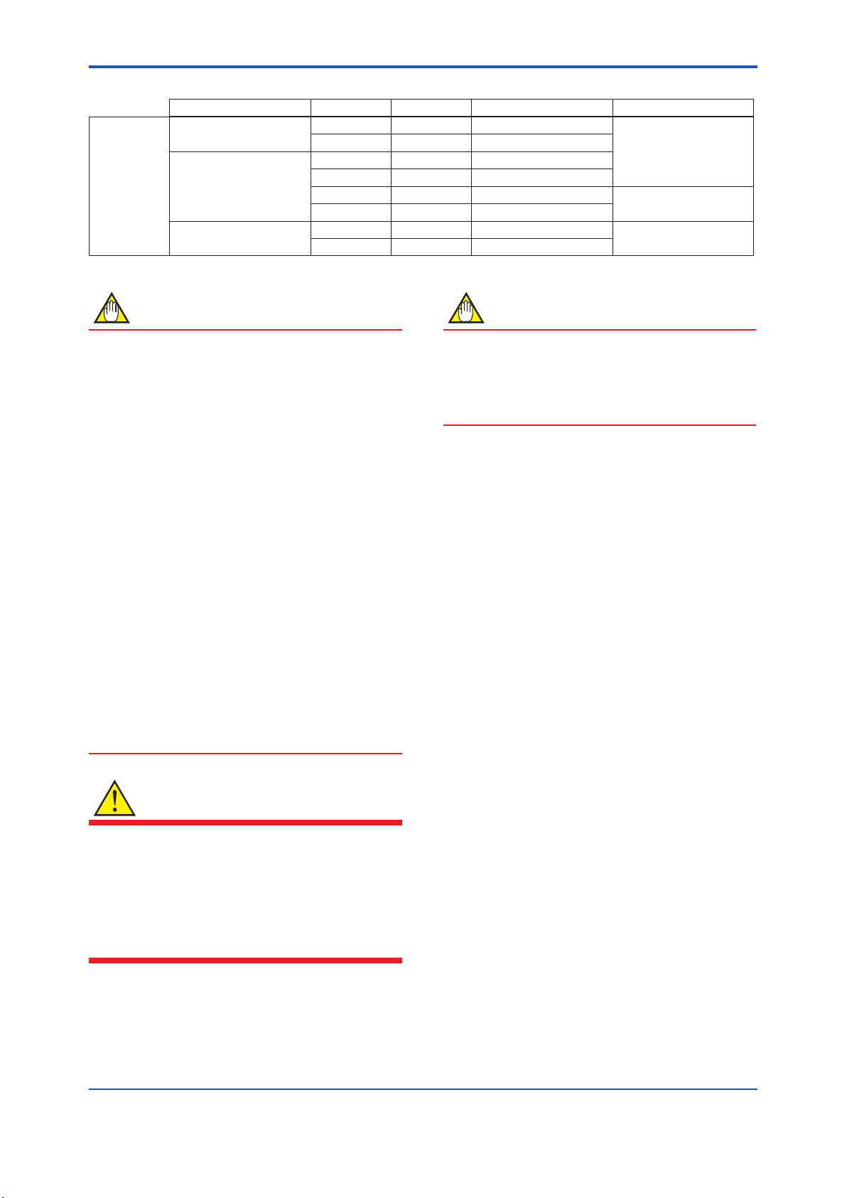
Table1.1 TransmitterModel
Transmitter Model Style code GS No. IM No.
Transmitter
section
Differential pressure
transmitter
EJX110A S3 GS 01C25B01-01EN
IM 01C25B01-01E
EJA110E S1, S2 GS 01C31B01-01EN
Gauge pressure
transmitter
EJX430A S2 GS 01C25E01-01EN
EJA430E S1, S2 GS 01C31E01-01EN
EJX530A S2 GS 01C25F01-01EN IM 01C25F01-01E
EJA530E S1, S2 GS 01C31F01-01EN
Absolute pressure
transmitter
EJX310A S2 GS 01C25D01-01EN IM 01C25B01-01E
EJA310E S1, S2 GS 01C31D01-01EN
NOTE
This manual describes the hardware
congurationsofthediaphragmsealsystem.
For wiring, please refer to the users’ manual(IM)
of each transmitter section as described in table
1.1 or “EJX/EJA-E series Installation Manual”(IM
01C25A01-01E) attached to the transmitter upon
shipment.
Forinformationonthesoftwareconguration
and operation, please refer to either
IM 01C25T03-01E for the BRAIN communication
type, or IM 01C25T01-06EN for the HART
communication type.
For FOUNDATION Fieldbus protocol type, please
refer to IM 01C25T02-01E.
For PROFIBUS PA protocol type, please refer to
IM 01C25T04-01EN.
To ensure correct use of this instrument, read
both the hardware and software manuals
thoroughly before use.
The manuals in pdf format are available on our
website (http://www.yokogawa.com/).
WARNING
When using the transmitters in a Safety
Instrumented Systems (SIS) application, refer
to Appendix 1 in either IM 01C25T01-06EN for
the HART protocol or IM 01C25T03-01E for the
BRAIN protocol. The instructions and procedures
in this section must be strictly followed in order to
maintain the transmitter for this safety level.
NOTE
When describing the model name like
EJC80, EJC81, or EJC50, it
shows the applicability for both EJXC80A
and EJAC80E, EJXC81A and EJAC81E, or
EJXC50A and EJAC50E respectively.
Regarding This Manual
• This manual should be provided to the end
user.
• The contents of this manual are subject to
change without prior notice.
• All rights reserved. No part of this manual may
be reproduced in any form without Yokogawa’s
written permission.
• Yokogawa makes no warranty of any kind with
regard to this manual, including, but not limited
to, implied warranty of merchantability and
tnessforaparticularpurpose.
• If any question arises or errors are found, or if
any information is missing from this manual,
please inform the nearest Yokogawa sales
ofce.
• Thespecicationscoveredbythismanualare
limited to those for the standard type under the
speciedmodelnumberbreak-downanddonot
cover custom-made instruments.
• Pleasenotethatchangesinthespecications,
construction, or component parts of the
instrumentmaynotimmediatelybereected
in this manual at the time of change, provided
that postponement of revisions will not cause
difcultytotheuserfromafunctionalor
performance standpoint.
<1. Introduction> 1-3
IM 01C25W01-01EN
• Yokogawa assumes no responsibility for this
product except as stated in the warranty.
• If the customer or any third party is harmed by
the use of this product, Yokogawa assumes
no responsibility for any such harm owing to
any defects in the product which were not
predictable, or for any indirect damages.
• The following safety symbols are used in this
manual:
WARNING
Indicates a potentially hazardous situation which,
if not avoided, could result in death or serious
injury.
CAUTION
Indicates a potentially hazardous situation which,
if not avoided, may result in minor or moderate
injury. It may also be used to alert against unsafe
practices.
IMPORTANT
Indicates that operating the hardware or software
in this manner may damage it or lead to system
failure.
NOTE
Draws attention to information essential for
understanding the operation and features.
Direct current
Functional grounding terminal
Caution
This symbol indicates that the operator must
refer to an explanation in the user’s manual
in order to avoid the risk of injury or death of
personnel or damage to the instrument.
Trademarks
• ‘DPharp’, ‘EJX’, ‘EJA’, ‘FieldMate’ and ‘BRAIN
TERMINAL’ are registered trademarks of
Yokogawa Electric Corporation. Company
names and product names used in this material
are registered trademarks or trademarks of their
respective owners.
• In this manual, trademarks or registered
trademarks are not marked with ™ or ®.
1.1 Safe Use of This Product
For the safety of the operator and to protect the
instrument and the system, please be sure to follow
this manual’s safety instructions when handling this
instrument. If these instructions are not heeded,
the protection provided by this instrument may be
impaired. In this case, Yokogawa cannot guarantee
that the instrument can be safely operated. Please
pay special attention to the following points:
(a) Installation
• This instrument may only be installed by an
engineer or technician who has an expert
knowledge of this device. Operators are not
allowed to carry out installation unless they
meet this condition.
• With high process temperatures, care must
be taken not to burn yourself by touching the
instrument or its casing.
• Never loosen the process connector nuts when
the instrument is installed in a process. This can
lead to a sudden, explosive release of process
uids.
• When draining condensate from the pressure
detector section, take appropriate precautions
to prevent the inhalation of harmful vapors and
thecontactoftoxicprocessuidswiththeskin
or eyes.
• When removing the instrument from a
hazardousprocess,avoidcontactwiththeuid
and the interior of the meter.
• All installation shall comply with local installation
requirements and the local electrical code.

<1. Introduction>1-4
IM 01C25W01-01EN
(b) Wiring
• The instrument must be installed by an
engineer or technician who has an expert
knowledge of this instrument. Operators are not
permitted to carry out wiring unless they meet
this condition.
• Before connecting the power cables, please
conrmthatthereisnocurrentowingthrough
the cables and that the power supply to the
instrument is switched off.
(c) Operation
• Wait 10 min. after the power is turned off, before
opening the covers.
(d) Maintenance
• Please carry out only the maintenance
procedures described in this manual. If you
require further assistance, please contact the
nearestYokogawaofce.
• Care should be taken to prevent the build up of
dust or other materials on the display glass and
the name plate. To clean these surfaces, use a
soft, dry cloth.
(e) ExplosionProtectedTypeInstrument
• Users of explosion protected type instruments
shouldreferrsttothesection“Installationof
an Explosion Protected Instruments” of the IM
(users’ manual) of the transmitter section.
• The use of this instrument is restricted to those
who have received appropriate training in the
device.
• Take care not to create sparks when accessing
the instrument or peripheral devices in a
hazardous location.
(f) Modication
• Yokogawa will not be liable for malfunctions or
damageresultingfromanymodicationmade
to this instrument by the customer.
(g) Product Disposal
• The instrument should be disposed of in
accordance with local and national legislation/
regulations.
1.2 Warranty
• The warranty shall cover the period noted on
the quotation presented to the purchaser at the
time of purchase. Problems occurring during
the warranty period shall basically be repaired
free of charge.
• If any problems are experienced with this
instrument, the customer should contact the
Yokogawa representative from which this
instrument was purchased or the nearest
Yokogawaofce.
• If a problem arises with this instrument,
please inform us of the nature of the problem
and the circumstances under which it
developed,includingthemodelspecication
and serial number. Any diagrams, data and
other information you can include in your
communication will also be helpful.
• Thepartyresponsibleforthecostofxingthe
problem shall be determined by Yokogawa
following an investigation conducted by
Yokogawa.
• The purchaser shall bear the responsibility for
repair costs, even during the warranty period, if
the malfunction is due to:
- Improper and/or inadequate maintenance by
the purchaser.
- Malfunction or damage due to a failure
to handle, use, or store the instrument in
accordancewiththedesignspecications.
- Use of the product in question in a location
notconformingtothestandardsspeciedby
Yokogawa, or due to improper maintenance
of the installation location.
- Failureordamageduetomodicationor
repair by any party except Yokogawa or an
approved representative of Yokogawa.
- Malfunction or damage from improper
relocation of the product in question after
delivery.
- Reasonofforcemajeuresuchasres,
earthquakes,storms/oods,thunder/
lightening, or other natural disasters, or
disturbances, riots, warfare, or radioactive
contamination.
<2. Handling Cautions> 2-1
IM 01C25W01-01EN
2. Handling Cautions
This chapter provides important information on how
to handle the transmitter. Read this carefully before
using the transmitter.
WARNING
The codes of the diaphragm seal system
represent a seal system type.
CEandotherstandardcerticationsareacquired
for each transmitter section.
Please refer to the designated sections of
each transmitter’s users’ manual(IM) for these
information as “Installation of an Explosion
Protected Instrument”, “EMC conformity standards”,
”Pressure Equipment Directive(PED)” and “Safety
Requirement Standards”.
Table2.1 TransmittersManualList
Diaphragm
Seal System
Applicable
Transmitter Users’ Manual(IM)
EJXC80A,
EJAC80E
EJX110A,
EJA110E,
EJX430A,
EJA430E IM 01C25B01-01E
EJXC81A,
EJAC81E
EJX310A,
EJA310E
EJXC50A,
EJAC50E
EJX530A,
EJA530E IM 01C25F01-01E
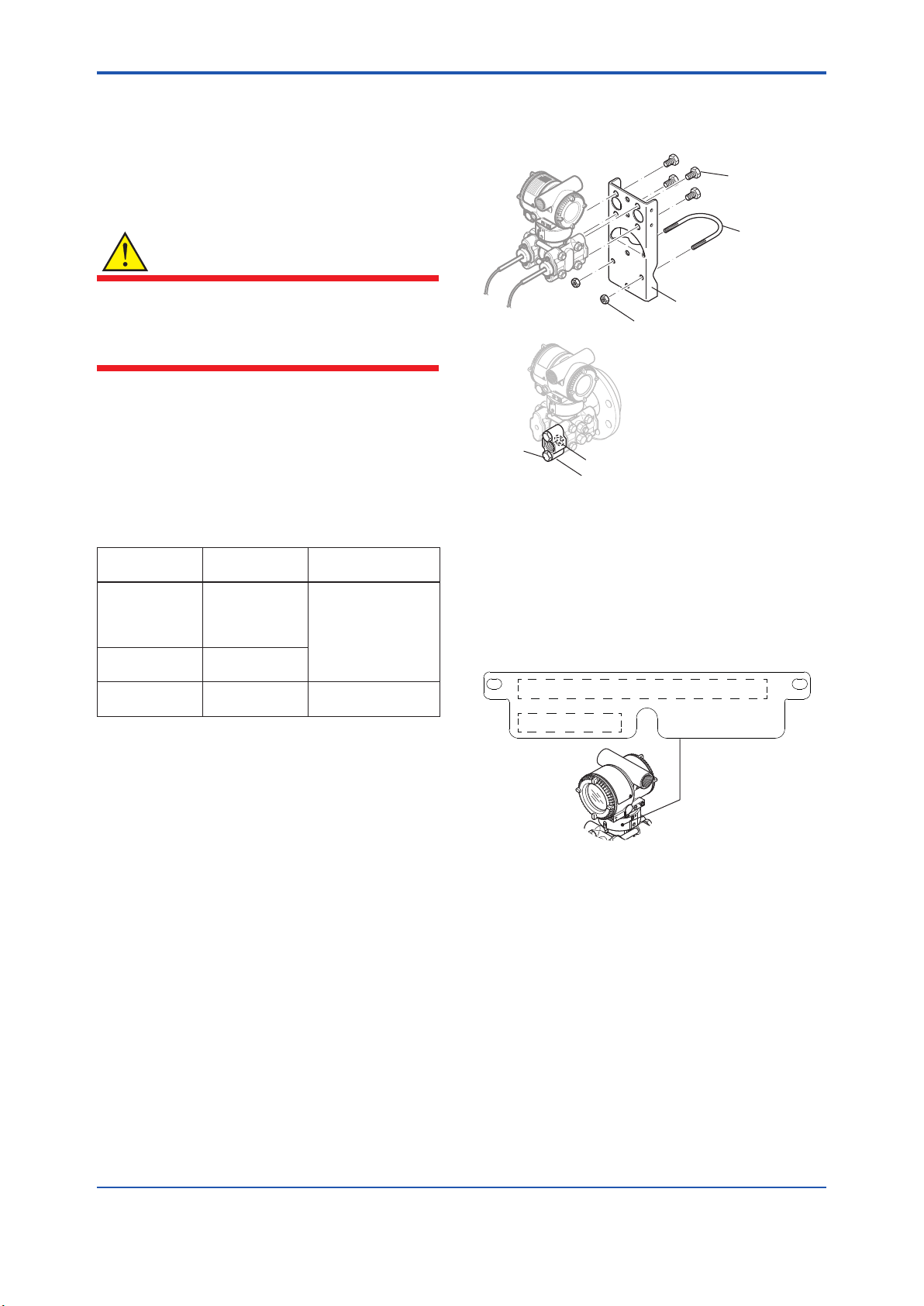
The transmitters are thoroughly tested at the
factory before shipment. When taking delivery of an
instrument, visually check them to make sure that
no damage occurred during shipment.
Also check that all the transmitter mounting
hardwareshowningure2.1isincluded.
If the transmitter is ordered without a mounting
bracket or a process connector, such mounting
hardware will not be included.
Mounting bracket
U-bolt nut
U-bolt
Transmitter
mounting bolt
F0201.ai
Process connector
Process connector gasket
Bolt
Figure 2.1 Transmitter Mounting Hardware
2.1 ModelandSpecications
Check
Themodelnameandspecicationsarewrittenon
the name plate attached to the case.
F0202.ai
Tag
Serial No. & Model
Figure 2.2 Name Plate

<2. Handling Cautions>2-2
IM 01C25W01-01EN
2.2 Unpacking
Keep the transmitter in its original packaging to
prevent it from being damaged during shipment.
Do not unpack the transmitter until it reaches the
installation site.
2.3 Storage
The following precautions must be observed when
storing the instrument, especially for a long period.
(a) Select a storage area which meets the following
conditions:
• It is not exposed to rain or subject to water
seepage/leaks.
• Vibration and shock are kept to a minimum.
• It has an ambient temperature and relative
humidity within the following ranges.
Ambient temperature:
–40* to 85°C without integral indicator
–30* to 80°C with integral indicator
*–15°Cwhen/HEisspecied.
Relative humidity:
0% to 100% R.H. (at 40°C)
Preferred temperature and humidity:
approx. 25°C and 65% R.H.
(b) When storing the transmitter, repack it carefully
in the packaging that it was originally shipped
with.
(c) If the transmitter has been used, thoroughly
cleanthechambersinsidethecoveranges
and the diaphragm surface of high pressure-
detector section, so that there is no process
uidremaininginsideoronit.Beforeplacingit
in storage, also make sure that the pressure-
detector section is securely connected to the
transmitter section.
2.4 Selecting the Installation
Location
The transmitter is designed to withstand severe
environmental conditions. However, to ensure
that it will provide years of stable and accurate
performance, take the following precautions when
selecting the installation location.
(a) Ambient Temperature
Avoid locations subject to wide temperature
variationsorasignicanttemperaturegradient.
If the location is exposed to radiant heat from
plant equipment, provide adequate thermal
insulation and/or ventilation.
(b) Ambient Atmosphere
Do not install the transmitter in a corrosive
atmosphere. If this cannot be avoided, there
must be adequate ventilation as well as
measures to prevent the leaking of rain water
and the presence of standing water in the
conduits.
(c) Shock and Vibration
Although the transmitter is designed to be
relatively resistant to shock and vibration, an
installation site should be selected where this is
kept to a minimum.
(d) Installation of Explosion-protected Transmitters
An explosion-protected transmitter is
certiedforinstallationinahazardousarea
containingspecicgastypes.Seesubsection
2.9 “Installation of an Explosion-Protected
Transmitters” of each transmitter’s manual as of
table 1.1.
2.5 Pressure Connection
WARNING
• Neverloosentheangeboltswhenan
instrument is installed in a process. The
device is under pressure, and a loss of seal
can result in a sudden and uncontrolled
releaseofprocessuid.
• Whendrainingtoxicprocessuidsthathave
condensed inside the pressure detector,
take appropriate steps to prevent the contact
ofsuchuidswiththeskinoreyesandthe
inhalationofvaporsfromtheseuids.
• Sincetheaccumulatedprocessuidmaybe
toxic or otherwise harmful, take appropriate
stepstopreventthecontactofsuchuids
with the skin or eyes and the inhalation
ofvaporsfromtheseuidsevenafter
dismounting the instrument from process line
for maintenance.
The following precautions must be observed
in order to safely operate the transmitter under
pressure.
(a) Make sure that all the process connector bolts
aretightenedrmly.
(b) Make sure that there are no leaks in the impulse
piping.
(c) Never apply a pressure higher than the
speciedmaximumworkingpressure.

<2. Handling Cautions> 2-3
IM 01C25W01-01EN
2.6 WaterproongofCable
Conduit Connections
Apply a non-hardening sealant to the threads
to waterproof the transmitter cable conduit
connections.
2.7 Restrictions on Use of Radio
Transceivers
IMPORTANT
Although the transmitter has been designed to
resist high frequency electrical noise, if a radio
transceiver is used near the transmitter or its
external wiring, the transmitter may be affected
by high frequency noise pickup. To test this, start
out from a distance of several meters and slowly
approach the transmitter with the transceiver
while observing the measurement loop for noise
effects. Thereafter use the transceiver outside
therangewherethenoiseeffectswererst
observed.
2.8 Insulation Resistance and
Dielectric Strength Test
Since the transmitter has undergone insulation
resistance and dielectric strength tests at the factory
before shipment, normally these tests are not
required. If the need arises to conduct these tests,
heed the following:
(a) Do not perform such tests more frequently than
is absolutely necessary. Even test voltages that
do not cause visible damage to the insulation
may degrade the insulation and reduce safety
margins.
(b) Never apply a voltage exceeding 500 V DC
(100 V DC with an internal lightning protector)
for the insulation resistance test, nor a voltage
exceeding 500 V AC (100 V AC with an internal
lightning protector) for the dielectric strength
test.
(c) Before conducting these tests, disconnect
all signal lines from the transmitter terminals.
The procedure for conducting these tests is as
follows:
• Insulation Resistance Test
1) Short-circuit the + and – SUPPLY terminals
in the terminal box. In case of 1 to 5 V output,
short-circuit the SUPPLY+, SUPPLY – and A
(VOUT +) terminals.
2) Turn OFF the insulation tester. Then connect
the insulation tester plus (+) lead wire to the
shorted SUPPLY terminals and the minus (–)
leadwire to the grounding terminal.
3) Turn ON the insulation tester power and
measure the insulation resistance. The voltage
shouldbeappliedasbrieyaspossibletoverify
thattheinsulationresistanceisatleast20MΩ.
4) After completing the test and being very careful
not to touch exposed conductors disconnect the
insulationtesterandconnecta100kΩresistor
between the grounding terminal and the short-
circuiting SUPPLY terminals. Leave this resistor
connected at least one second to discharge any
static potential. Do not touch the terminals while
it is discharging.
• Dielectric Strength Test
1) Short-circuit the + and – SUPPLY terminals
in the terminal box. In case of 1 to 5 V output,
short-circuit the SUPPLY+, SUPPLY – and A
(VOUT +) terminals.
2) Turn OFF the dielectric strength tester. Then
connect the tester between the shorted
SUPPLY terminals and the grounding terminal.
Be sure to connect the grounding lead of the
dielectric strength tester to the ground terminal.
3) Set the current limit on the dielectric strength
tester to 10 mA, then turn ON the power and
gradually increase the test voltage from ‘0’ to
thespeciedvoltage.
4) Whenthespeciedvoltageisreached,holdit
for one minute.
5) After completing this test, slowly decrease the
voltage to avoid any voltage surges.

<3. Component Names> 3-1
IM 01C25W01-01EN
3. Component Names
EJC80Differential pressure transmitter
EJC80Differential pressure transmitter
Cover flange
Diaphragm seal
(high pressure side)
Diaphragm seal
(low pressure side)
Capillary tube
Pressure detector section
Transmitter section*
EJC80Pressure transmitter
EJC81Absolute Pressure transmitter
F0301.ai
Cover flange
Diaphragm seal
Pressure detector section
With C10FR
Flushing connection ring
C10FR
Flushing connection ring
Vent, drain plug
EJC50Pressure transmitter
Diaphragm seal
Pressure detector section
Diaphragm seal
(high pressure side)
Cover flange
Pressure detector section
*See figure 3.2. Transmitter section*
*See figure 3.2.
Transmitter section*
*See figure 3.2.
Transmitter section*
*See figure 3.2.
Vent, drain plug
Process connection
(low pressure side)
Process connector
EJC80Hygienic Differential pressure transmitter
Cover flange
Diaphragm seal
(high pressure side)
Diaphragm seal
(low pressure side)
Capillary tube
Transmitter section*
*See figure 3.2.
EJC80Hygienic pressure transmitter
Transmitter section*
*See figure 3.2.
Diaphragm seal
(high pressure side)
Cover flange
Pressure detector section
Vent, drain plug
Pressure detector section
Figure 3.1 Components Name(Figures Show Flush Type Diaphragm Seals)
<3. Component Names>3-2
IM 01C25W01-01EN
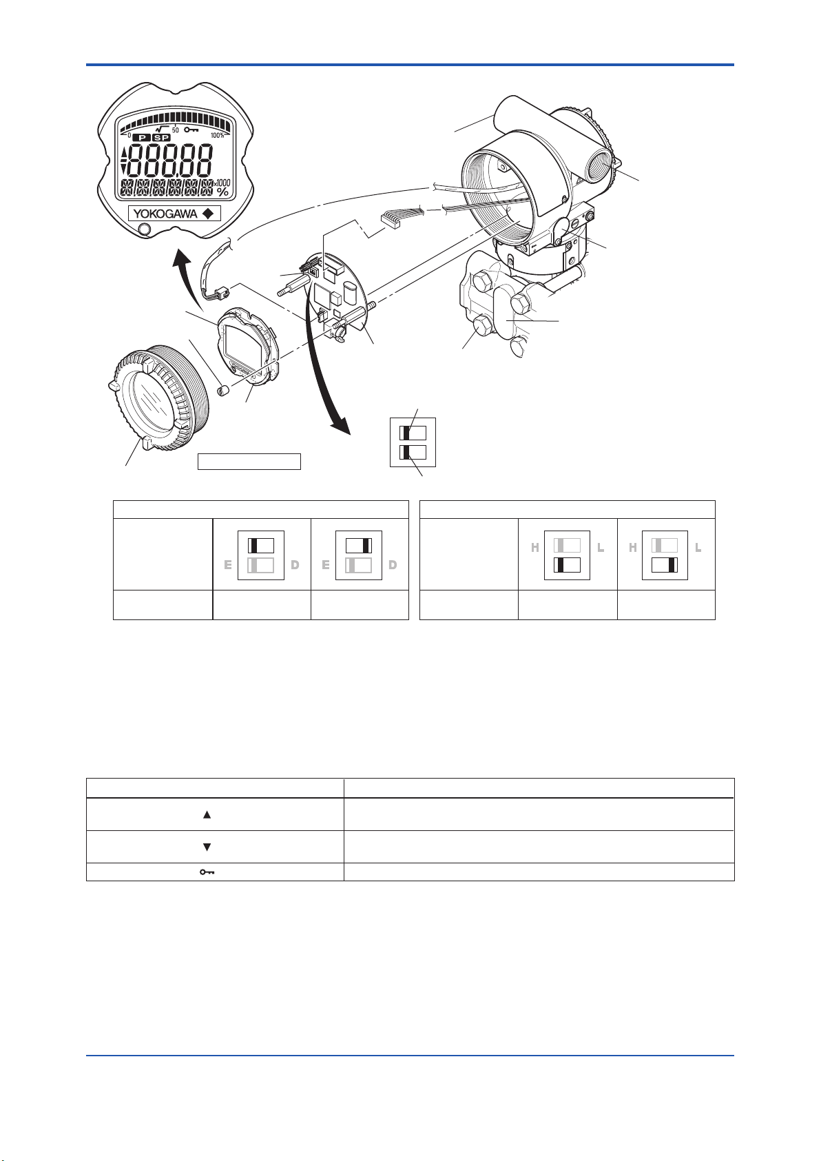
HIGH LOW
H L H L
F0302.ai
H L
E D
H L
E D
YES
(Write disabled)
NO
(Write enabled)
Slide switch
(Note 2)
Integral
indicator (Note 1)
Mounting screw
Amplifier Cover
Burnout direction switch (BO) Hardware write protection switch (WR)
Burnout Direction
Switch Position
Burnout Direction
Write Protection
Switch Position
Write Protection
Transmitter section
(Note 2) (Note 2)
CPU
assembly
Burnout direction switch
BO H L
WR E D
Write protection switch
Range-setting
switch (Note 1)
Zero-adjustment screw
Conduit connection
External indicator
conduit connection (Note 1)
Cover flange
(only for EJC80and EJC81)
Bolt for flange
(only for EJC80and EJC81)
Note1: See“ModelandSufxCodes”inchapter7fordetails.
Note2: ApplicableforBRAIN/HARTcommunicationtype.Settheswitchesasshowninthegureabovetosettheburn-outdirection
andwriteprotection.TheBurnoutswitchissettotheHsidefordelivery(unlessoptioncode/C1or/C2isspeciedintheorder),
andthehardwarewriteprotectionswitchissettoEside.Thesettingoftheswitchescanbeconrmedviacommunication.An
external zero adjustment screw can only be disabled by communication. To disable the screw, set a parameter before activating
the hardware write protect function. See each communication manual for details.
Figure 3.2 Component Names (Transmitter Section)
Table3.1 DisplaySymbol
Display Symbol Meaning of Display Symbol
The output signal being zero-adjusted is increasing.
Besides, this symbol lights when local parameter setting is in progress.
The output signal being zero-adjusted is decreasing.
Besides, this symbol lights when local parameter setting is in progress.
F0303.ai
Write protect function is enabled.

<4. Installation> 4-1
IM 01C25W01-01EN
4. Installation
4.1 Precautions
Before installing the transmitter, read the cautionary
notes in Section 2.4, “Selecting the Installation
Location.” For additional information on the
ambient conditions allowed at the installation
location, refer to in the chapter 7 “Standard
Specications.”
IMPORTANT
• When welding piping during construction,
take care not to allow welding currents to
owthroughthetransmitter.
• Do not step on this instrument after
installation.
• For the EJC80gauge transmitter, there
is a small hole in the low pressure side
coverangethatisusedtomeasurethe
atmospheric pressure.
The hole must not face upward. See
“Dimensions,” in the chapter 7 for the
location of the hole.
• Never loosen the four bolts securing the
coveranges(Refertogure3.2)for
EJC80and EJC81diaphragm seal
system.
If the seal liquid leaks, the transmitter cannot
be used.
4.2 Mounting the Diaphragm
Seals (Remote Seals)
4.2.1 MountingFlushtype/Extendedtype
Seals
Mountthediaphragmsealsusingtheangesas
shown in Figure 4.1 Figure 4.2 shows how to mount
thediaphragmsealsonatank.Thematingange,
gasket, bolts and nuts are to be procured by the
customer.
Nut
Flange
Diaphragm
Ød
Gasket
F0401.ai
Bolt
The product is shipped with
these parts assembled.
Correctly install the diaphragm seals on
the high and low pressure sides of the
process (The label on each diaphragm
seal is marked HIGH or LOW.)
Figure 4.1 Mounting the Diaphragm Seals
(Remote seal)
IMPORTANT
Please use a gasket with an inside diameter
(ød) that is greater than the diameter of the
diaphragm seal. If a gasket with a smaller
inside diameter is used, the diaphragm may not
function correctly. (Refer to ‘Dimensions’ in the
chapter 7.)
<4. Installation>4-2
IM 01C25W01-01EN
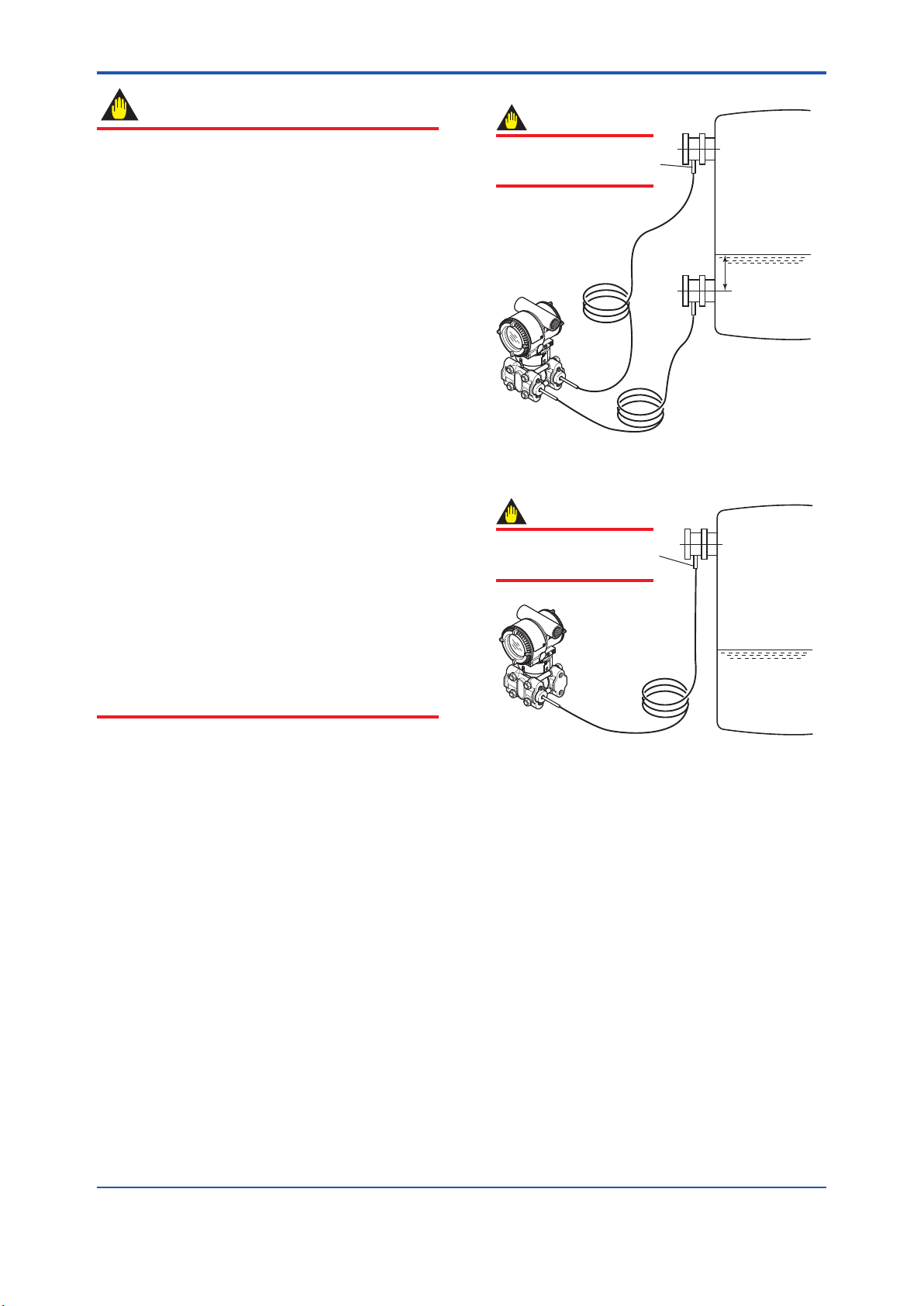
IMPORTANT
• When measuring the liquid level of the tank,
the minimum liquid level (zero point) must
be set to a level at least 50 mm above the
center of the high pressure side diaphragm
seal (see Figure 4.2).
• Correctly install the diaphragm seals on the
high and low pressure sides of the process,
checking the label on each seal.
• To avoid measuring error duets temperature
difference between the two diaphragm
seals, capillary tube must be bound together.
Thecapillarytubemustbesecurelyxed
to the tank wall to prevent movement by
wind or vibration. If the capillary tube is too
long, loosely coil the extra tube portion (coil
diameter of 300 mm or more) and secure the
coiled tube with a clamp.
• During the diaphragm seal installation,
ensure as far as possible that no seal liquid
head pressure is applied to the diaphragm
seals.
• Exercise care so as not to damage
diaphragm surfaces. Since the diaphragm
protrudesapprox.1mmfromtheange
surface, do not place the pressure detector
section face down on a surface as this can
damage the diaphragm.
• Do not sharply bend or twist capillary tube or
apply excessive stress to them.
F0402.ai
50mm minimum
Minimum
liquid level
High
pressure
side
Install the sealed diaphragm
so that the shank positions
downward.
Low
pressure
side
IMPORTANT
The transmitter should be
installed as low as possible
below the position where
the high pressure side
diaphragm seal is installed.
Install the sealed diaphragm
so that the shank positions
downward.
IMPORTANT
Figure 4.2 Installing the Diaphragm Seals to a
Tank
<4. Installation> 4-3
IM 01C25W01-01EN
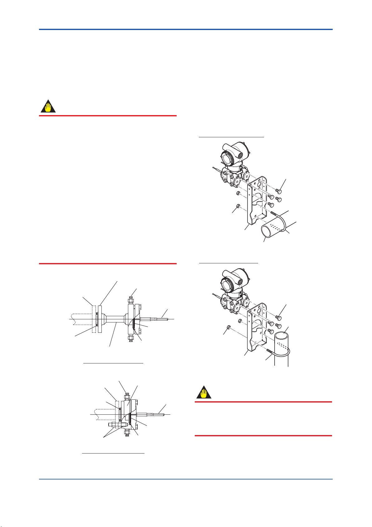
4.2.2 Mounting Inner Diaphragm Type
Seals
Install the seal in accordance with the Figure 4.3.
Thebolts,nuts,matingangeandgasketaretobe
procured by the customer.
Position the connection adapter so that the drain/
vent plugs are aligned straight up and down.
IMPORTANT
• Please use the gasket whose inside
diameter is greater than the inside pipe
diameter.
• Do not sharply bend or twist capillary tube or
apply excessive stress to them.
• For differential pressure transmitters,
capillary tubes must be bundled together
to avoid measuring error duets temperature
difference between the two diaphragm seals.
• The product is performing temperature
compensation by the temperature sensor in
the transmitter section. When a difference
of temperature appears between the
transmitter section and capillary tube, an
output error occurs.
Please use thermal insulants to decrease the
effect of temperature difference between the
transmitter section and capillary tube.
Mating flange
Procured by the customer
Gasket
Procured by the customer
Connection flange
Connection adapter
Drain/vent plug
Capillary tube
Diaphragm
Gasket
Stud bolt/nut
Attached to product
Flange connection type
Adapter connection type
Mating flange
Procured by the customer
Gasket
Procured by the customer
Connection adapter
Drain/vent plug
Capillary tube
Diaphragm
Gasket
F0403.ai
Figure 4.3 Mounting Inner Diaphragm Seal
4.3 Mounting EJC80and
EJC81with Remote Seal
■ Thetransmittercanbemountedonanominal
50 mm (2 to inch) pipe using the mounting
bracket supplied, as shown in Figure 4.4.
The transmitter can be mounted on either a
horizontal or a vertical pipe.
■ Whenmountingthebracketonthetransmitter,
tighten the (four) bolts that hold the transmitter
to a torque of approximately 39 N·m {4 kgf·m}.
F0404.ai
U-bolt nut
Mounting bracket
Mounting bracket
50mm (2-inch) pipe
U-bolt
U-bolt
Horizontal pipe mounting
50mm (2-inch) pipe
Transmitter
mounting bolt
Transmitter
mounting bolt
U-bolt nut
Vertical pipe mounting
Figure 4.4 Transmitter Mounting
IMPORTANT
When using the absolute pressure transmitter of
M-Capsule, please care so that the sum of the
head pressure and atmospheric pressure does
not exceed Upper Range Limit (130 kPa abs.)

<4. Installation>4-4
IM 01C25W01-01EN
IMPORTANT
The transmitter should be installed at least
600 mm below the high pressure (HP) process
connection to ensure a positive head pressure
oflluid.Payspecialattentiontovacuum
applications.
If it can not be installed at least 600 mm below
the HP process connection, please use the
equation below:
h= × 0.102 [mm]
(P–P0)
ds
h: Vertical height between the HP process
connection and the transmitter (mm)
h≤0: Installthetransmitteratleasth(mm)
below the HP process connection
h>0: Install the transmitter at most h (mm)
above the HP process connection
P: Pressure in the tank (Pa abs)
P0: Minimum working pressure limit of the
transmitter (Pa abs). See below table.
[ForlluidcodeA,B,D,E,F,P]
Wetted parts
material code
Capillary
length
Process connection
size code
6 9
S
1 to 5 m 6790 3190
6 to 10 m 10030 3520
11 to 15 m 13310 3840
H
1 to 5 m 19150 6140
6 to 10 m 32090 8290
11 to 15 m -------- 10480
T
1 to 5 m 9620 3620
6 to 10 m 15090 4210
11 to 15 m -------- 4800
U
1 to 5 m 9540 4750
6 to 10 m 14930 6050
11 to 15 m -------- 7360
M
1 to 5 m 10910 3970
6 to 10 m 17380 4780
11 to 15 m -------- 5600
K
1 to 5 m 10910 3970
6 to 10 m 17380 4780
11 to 15 m -------- 5600
V
1 to 5 m 10910 3970
6 to 10 m -------- 4780
11 to 15 m -------- --------
J
1 to 5 m -------- 13070
6 to 10 m -------- 19540
11 to 15 m -------- --------
[Forlluidcode1,2,4]
Wetted parts
material code
Capillary
length
Process connection
size code
6 9
S1 to 5 m 2570 320
6 to 10 m 4680 530
H1 to 5 m 10220 2050
6 to 10 m 18650 3450
T1 to 5 m 4270 570
6 to 10 m 7780 960
ds: Specicgravityoflluid(at25°C).
See table 1 in the chapter 7.
F0405.ai
P
Low pressure side
High
pressure
side
(+)
(–)
0
h
Figure4.5 ExampleofInstallationtoTankfor
Differential Pressure Transmitter
(Caution on Installation)
F0406.ai
(+)
0
(–) P
h
Figure4.6 ExampleofInstallationtoTankfor
Gauge Pressure Transmitter
(Caution on Installation)
<4. Installation> 4-5
IM 01C25W01-01EN
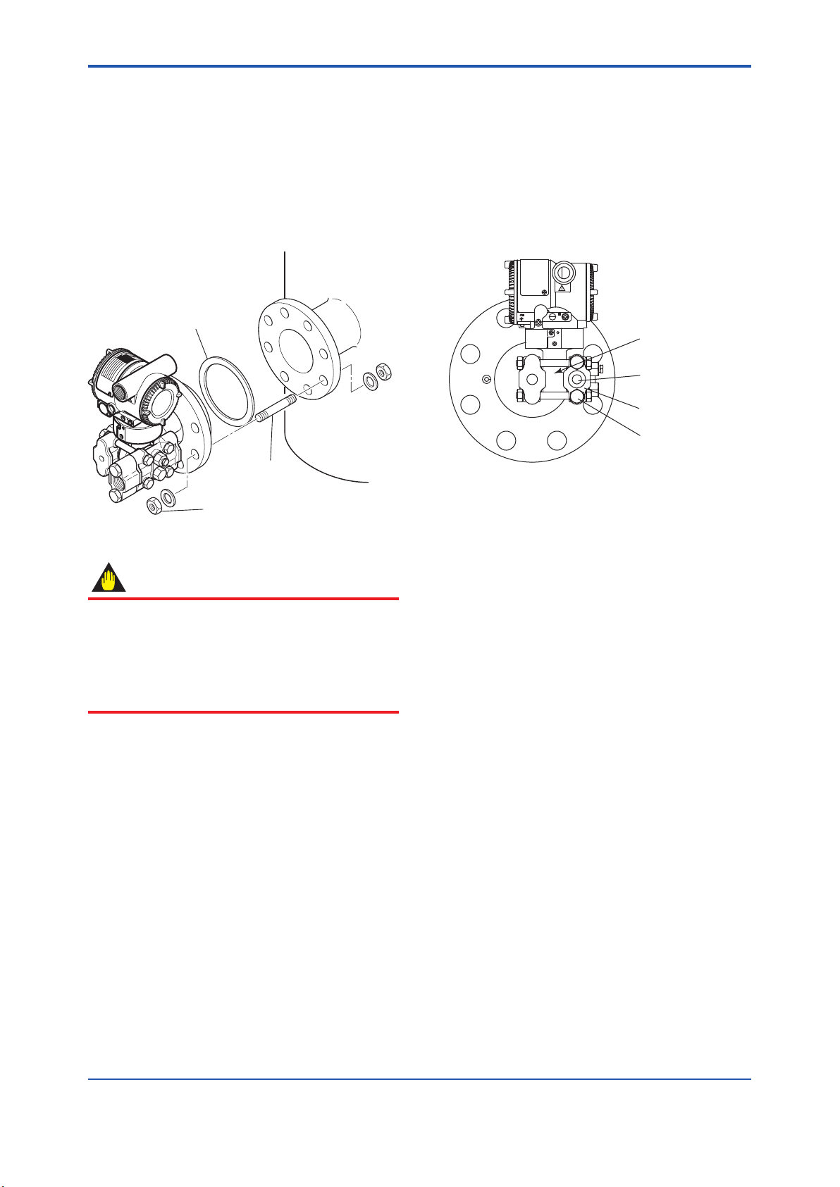
4.5 Mounting EJC80with
Direct Mount Seal
4.5.1 Mounting
The transmitter is mounted on a process using its
high-pressuresideangeasshowninFigure4.7.
Thematingange,gasket,studboltsandnutsare
to be procured by the customer.
F0407.ai
Gasket
Stud bolt
Nut
Figure 4.7 Transmitter Mounting
IMPORTANT
Please use a gasket with an inside diameter
(ød) that is greater than the diameter of the
diaphragm seal. If a gasket with a smaller
inside diameter is used, the diaphragm may not
function correctly. (Refer to ‘Dimensions’ in the
chapter 7.)
4.5.2 Connecting Impulse Piping to the
Transmitter
The impulse piping that connects the process
outputs to the transmitter must convey the process
pressure accurately. If, for example, gas collects in
aliquid-lledimpulseline,orthedrainofagas-lled
impulse line becomes plugged, it will not convey the
pressure accurately. Since this will cause errors in
the measurement output, select the proper piping
methodfortheprocessuid(gas,liquid,orsteam).
Pay careful attention to the following points when
routing the impulse piping and connecting the
impulse piping to a transmitter.
(1) Check the High and Low Pressure
Connections on the Transmitter (Figure 4.8)
The letters H and L on the capsule assembly
indicate the high and low pressure sides. For
liquid level measurement in an open tank, the low
pressure side measures atmospheric pressure.
For a closed tank, connect the impulse line to the
low pressure side of the transmitter to measure the
pressure in the tank.
F0408.ai
H and L appear here
Low pressure
connection
Process connector
Bolt
Figure4.8 HandLSymbolsonaCapsule
Assembly
(2) Tightening the Process Connector
Mounting Bolts
After connecting the impulse line, tighten the
process connector mounting bolts uniformly.
(3) Removing the Impulse Piping Connecting
Port Dustproof Cap
The impulse piping connecting port of the
transmitter is covered with a plastic cap to keep out
dust. This cap must be removed before connecting
the line. (Be careful not to damage the threads
when removing this cap. Never insert a screwdriver
or other tool between the cap and port threads to
remove the cap.)
(4) Impulse Piping Slope
The impulse piping must be routed with only an
upward or downward slope. Even for horizontal
routing, the impulse piping should have a slope of
at least 1/10 to prevent condensate (or gases) from
accumulating in the pipes.
(5) Preventing Freezing
Ifthereisanyriskthattheprocessuidinthe
impulse piping or transmitter could freeze, use a
steam jacket or heater to maintain the temperature
oftheuid.

<4. Installation>4-6
IM 01C25W01-01EN
NOTE
After completing the connections, close the
valves on the process pressure taps (main
valves), the valves at the transmitter (stop
valves), and the impulse piping drain valves,
so that condensate, sediment, dust and other
extraneous material cannot enter the impulse
piping.
(6) ImpulsePipingConnectionExamples
Figure 4.9 shows examples of typical impulse
piping connections. Before connecting the
transmitter to the process, study the transmitter
installation location, the process piping layout,
andthecharacteristicsoftheprocessuid
(corrosiveness,toxicity,ammability,etc.),etc.and
make appropriate changes and additions to the
connectioncongurations.
F0409.ai
Pipe (opened to atmosphere
at low pressure side)
Open Tank
Closed Tank
Tap valve
Union or flange
Vent plug
Tee
Drain valve
Drain plug
Figure4.9 ImpulsePipingConnectionExamples
4.6 Mounting EJC50with
Direct Mount Seal
The transmitter is mounted on a process using its
high-pressuresideangeasshowninFigure4.10.
Thematingange,gasket,studboltsandnutsare
to be procured by the customer.
F0410.ai
Gasket
Stud bolt
Nut
Figure 4.10 Transmitter Mounting
IMPORTANT
Please use a gasket with an inside diameter
(ød) that is greater than the diameter of the
diaphragm seal. If a gasket with a smaller
inside diameter is used, the diaphragm may not
function correctly. (Refer to ‘Dimensions’ in the
chapter 7.)
<4. Installation> 4-7
IM 01C25W01-01EN
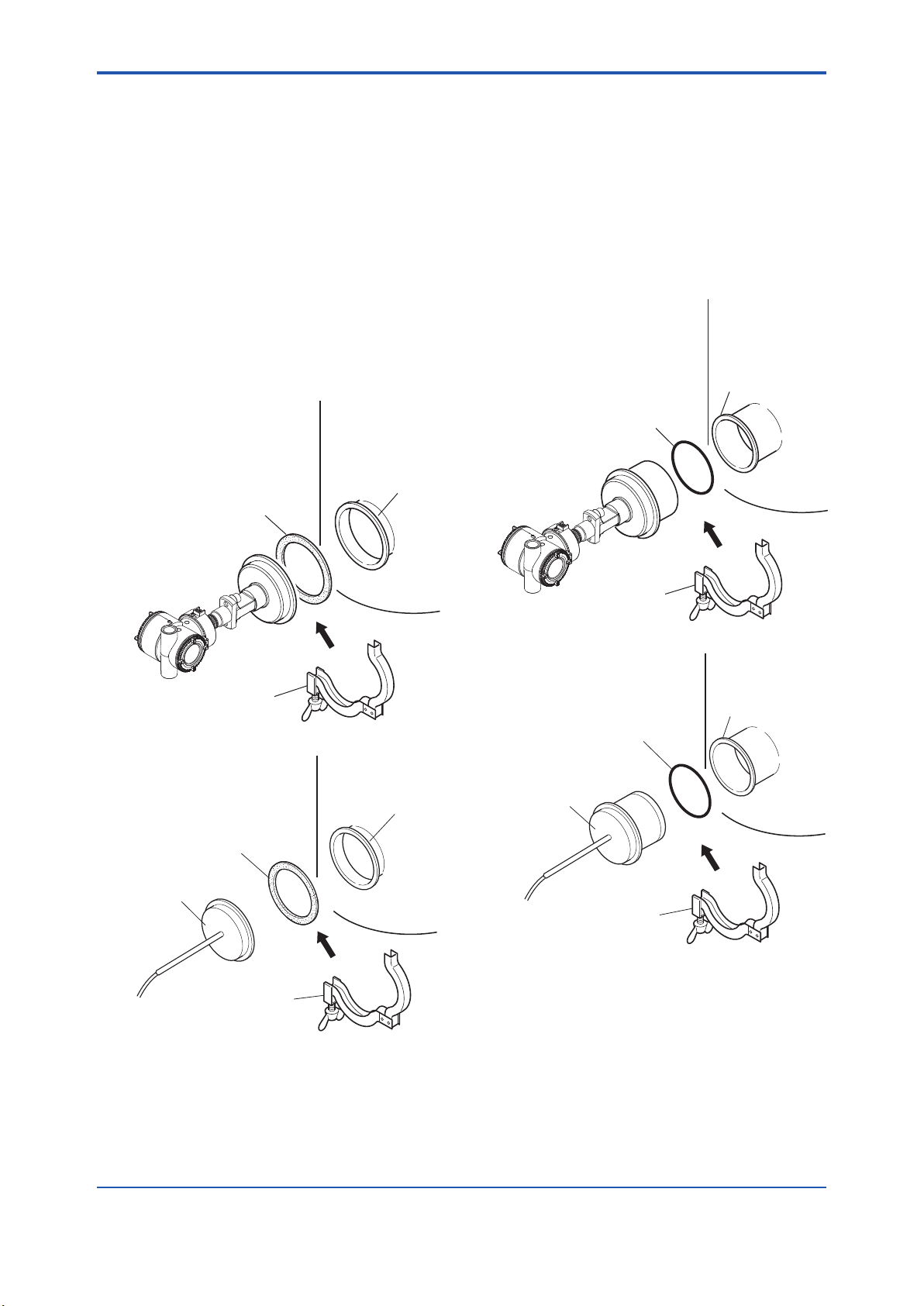
4.7 Mounting EJC50and
EJC80with Hygienic
Seal
4.7.1 Hygienic Seal (Flush Type)
Theushdiaphragmtypeismountedonaprocess
tank as shown in Figure 4.11.
1) Fit the gasket into the gasket slot and attach it
to the transmitter .
2) With the gasket attached, mount the transmitter
onto the sleeve.
3) Use the clamp to secure the connecting section
in position.
F0411.ai
*: The customer should prepare
the mating gasket and clamp,
They are also available from
Yokogawa; if required, please
order them separately. Refer to
Table 4.2.
Tank
Sleeve
Gasket* (Optional)
Clamp* (Optional)
Tank
Sleeve
Gasket* (Optional)
Diaphragm seal
Clamp* (Optional)
Figure 4.11 Mounting Hygienic Seal (Flush Type)
4.7.2 HygienicSeal(ExtendedType)
The extended diaphragm type is mounted on a
process tank as shown in Figure 4.12.
1) Fit the O-ring into the O-ring slot of the
transmitter.
2) With the O-ring attached, mount the transmitter
onto the tank spud.
3) Use the clamp to secure the connecting section
in position.
F0412.ai
*: The customer should prepare the
mating O-ring, clamp, and tank
spud. They are also available
from Yokogawa; if required,
please order them separately.
Refer to Table 4.1 and 4.2.
Tank
Tank spud*
(sold separately)
O-ring* (Optional)
Clamp* (Optional)
Diaphragm seal
O-ring* (Optional)
Clamp* (Optional)
Tank
Tank spud*
(sold separately)
Figure4.12 MountingHygienicSeal(Extended
Type)
For the installation of a tank spud, read the following
section very carefully.
This manual suits for next models
5
Table of contents


