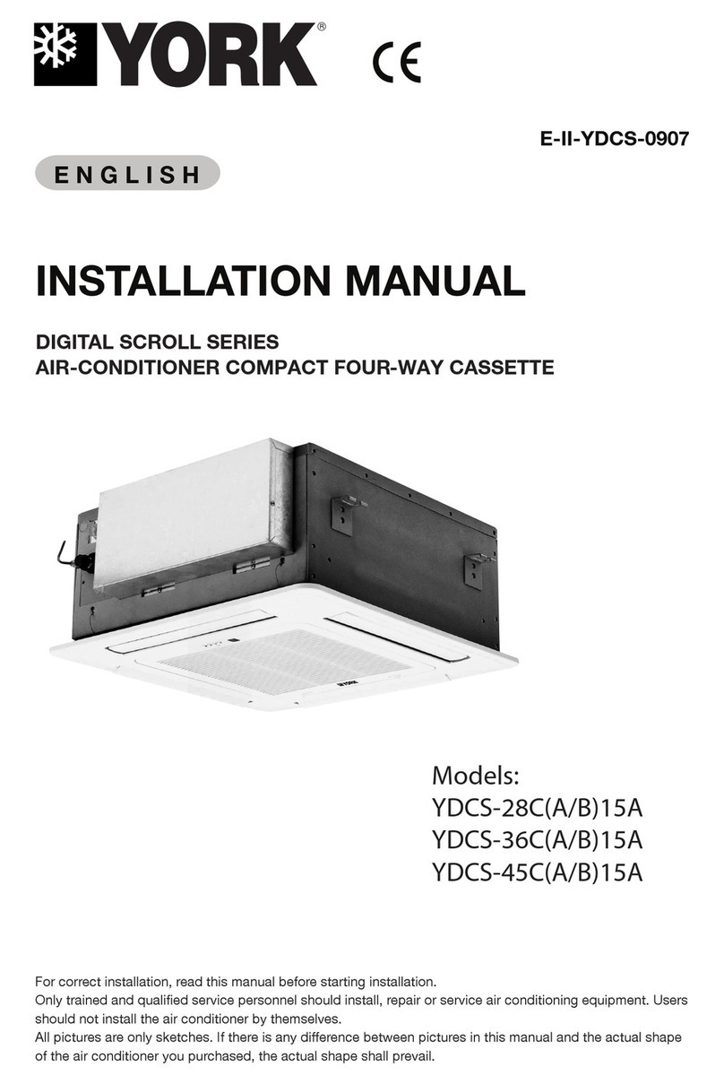
York CH012 User manual

INSTALLATION
INSTRUCTION
CAUTION: READ ALL SAFETY GUIDES BEFORE YOU
START TO INSTALL THIS UNIT.
SAVE THIS MANUAL
036-33073-001 Rev. A (0701)
WATER COOLED AIR
CONDITIONING UNITS
MODELS: CH012 - CH060 AND
CU012 - CU060
HORIZONTAL UNIT SHOWN
MODEL NUMBER
HORIZONTAL VERTICAL CAPACITY
TONS
CH012A06A1 CU012A06A1 I
CH018A06A1 CU018A06A1 1 1/2
CH024A06A1 CU024A06A1 2
CH030A06A1 CU030A06A1 2 1/2
CH030A25A1 CU030A25A1 2 1/2
CH036A06A1 CU036A06A1 3
CH036A25A1 CU036A25A1 3
CH048A06A1 CU048A06A1 4
CH048A25A1 CU048A25A1 4
CH060A06A1 CU060A06A1 5
CONTENTS
INTRODUCTION ..............................................................3
INSPECTION OF EQUIPMENT .......................................3
SELECTION OF INSTALLATION LOCATION .................3
CLEARANCES REQUIRED .............................................3
CHECKING THAT THE UNIT IS LEVEL ..........................3
UNIT MOUNTINGS ..........................................................3
UNIT WEIGHTS ................................................................3
DUCT CONNECTIONS ....................................................3
ELECTRICAL POWER SUPPLY AND CONNECTIONS ..4
ROOM THERMOSTAT AND CONTROL WIRING ...........4
BLOWER PERFORMANCE .............................................4
CONDENSER WATER SUPPLY AND CONNECTIONS .4
WATER REGULATING VALVE – INSTALLATION .........5
WATER REGULATING VALVE – ADJUSTMENT ............5
CONDENSATE DRAIN PIPING .......................................5
R-22 REFRIGERANT CHARGE .......................................5
OPERATION .....................................................................6
MAINTENANCE ................................................................6
®

036-33073-001 Rev. A (0701)
2UnitaryProductsGroup
IMPROPER INSTALLATION MAY CREATE A
CONDITION WHERE THE OPERATION OF THE
PRODUCT COULD CAUSE PERSONAL INJURY
OR PROPERTY DAMAGE.
IMPROPER INSTALLATION, ADJUSTMENT,
ALTERATION, SERVICE OR MAINTENANCE
CAN CAUSE INJURY OR PROPERTY DAMAGE.
REFER TO THIS MANUAL FOR ASSISTANCE
OR ADDITIONAL INFORMATION, CONSULT A
QUALIFIED INSTALLER, SERVICE AGENCY OR
THE GAS SUPPLIER.
THIS PRODUCT MUST BE INSTALLED IN
STRICT COMPLIANCE WITH THE ENCLOSED
INSTALLATION INSTRUCTIONS AND ANY
APPLICABLE LOCAL, STATE, AND NATIONAL
CODES INCLUDING BUT NOT LIMITED TO,
BUILDING, ELECTRICAL AND MECHANICAL
CODES.
WARNING
CAUTION
CONTENTS
INTRODUCTION . . . . . . . . . . . . . . . . . . . . . . . . . . . . . . . . . 3
INSPECTION OF EQUIPMENT . . . . . . . . . . . . . . . . . . . . . 3
SELECTIONOFINSTALLATIONLOCATION ..........3
CLEARANCESREQUIRED ........................3
CHECKING THAT THE UNIT IS LEVEL . . . . . . . . . . . . . . . 3
UNITMOUNTINGS ...............................3
DUCT CONNECTIONS . . . . . . . . . . . . . . . . . . . . . . . . . . . . 3
ELECTRICAL POWER SUPPLY AND CONNECTIONS . . 4
ROOMTHERMOSTATANDCONTROLWIRING .......4
BLOWERPERFORMANCE ........................4
CONDENSER WATER SUPPLY AND CONNECTIONS . . 4
WATER REGULATING VALVE – INSTALLATION . . . . . . . 5
WATER REGULATING VALVE – ADJUSTMENT . . . . . . . 5
CONDENSATEDRAINPIPING .....................5
OPERATION ....................................6
MAINTENANCE .................................6
LIST OF TABLES
UNITWEIGHTS .................................3
EVAPORATOR BLOWER PERFORMANCE (CFM) . . . . . . 4
WATERVALVESIZES ............................5
R-22REFRIGERANTCHARGE .....................5
AIR FILTER APPLICATIONS. . . . . . . . . . . . . . . . . . . . . . . . 6
LIST OF FIGURES
W/CUNITS;208-230V/3PH/60HZ ..................7
W/C SINGLE PHASE UNITS; 208 - 230V/1PH/60HZ . . . . . 8
W/C AIR CONDITIONERS ELECTRICAL DATA . . . . . . . . 9
HORIZONTAL WATER COOLED UNITS DIMENSIONAL
DATA.........................................10
VERTICAL WATER COOLED UNITS DIMENSIONAL
DATA.........................................11

036-33073-001 Rev. A (0701)
Unitary Products Group 3
INTRODUCTION
York model CH and CU units are completely self-contained
air conditioning units with water-cooled condensers.
Cooling water for the condenser may be from the mains, a
cooling tower, or a chilled water system. Automatic water flow
regulating valves are available as field installed accessories.
The water cooled condenser and all water piping within the
unit are designed and approved for water pressures up to
400 P.S.I.G. Automatic water flow regulating valves are avail-
able for either 150 P.S.I.G. or 350 P.S.I.G. Detailed informa-
tion on condenser pressure drops, water valve selections,
installation, and adjustment is given on page 5 of these
instructions.
Remote 24-volt room thermostats control all units. All single-
phase units have start capacitors and relays. Off cycle time
delay relays are not required.
The units are designed for indoor installation only. They are
not intended or approved for outdoor installation. The units
can be installed in the conditioned space or in an adjacent
utility room. The horizontal units are ideal for hanging in a
ceiling space above a suspended ceiling.
INSPECTION OF EQUIPMENT
The unit should be inspected as soon as it is received for any
possible damage during transit. Any damage observed must
be noted on the carrier's freight bill. The carrier’s agent
should make a separate written request for an inspection.
The contractor is responsible for negotiating shipping dam-
age claims with the carrier. The manufacturer is not responsi-
ble for shipping damage and it is not covered by warranty.
SELECTION OF INSTALLATION LOCATION
The units are designed for indoor installation only and are not
intended or approved for outdoor use. The units must not be
installed in unheated areas where the temperature could fall
below freezing. The units can be installed in the conditioned
space or in an adjacent utility room. The horizontal units are
ideal for hanging in a ceiling space above a suspended ceil-
ing. The unit should be installed as close to the conditioned
space as possible.
When deciding where to locate the unit, the following require-
ments must be considered:
1. Power wiring to the correct power source for the unit.
2. Condenser water supply and return piping.
3. Condensate drain piping and trap leading to an open
drain.
4. Air distribution ducts to be of adequate size and not
excessively long.
5. Try to minimize sound transmission from the unit to the
conditioned space.
6. Access is required for maintenance and service.
CLEARANCES REQUIRED
Twenty-four (24) inch clearance is required at each end of the
unit for service access. Eighteen (18) inch clearance is rec-
ommended on the side where the discharge duct is con-
nected. The clearance on the return air side should be a
minimum of six inches in order to reach the air filter and slide
it out.
CHECKING THAT THE UNIT IS LEVEL
It is very important to check the level of the unit. Use a spirit
level to make sure the unit is level or sloping slightly towards
the drain outlet connection.
UNIT MOUNTINGS
The horizontal units should be supported from the holes in
the rail extensions at the four corners. The horizontal units
may be suspended from above, using steel threaded rods
having a minimum diameter of 3/8 inch. Four rubber bushings
are supplied with the unit to be placed between the unit and
the supporting rods to absorb vibration.
TABLE 1: UNIT WEIGHTS
DUCT CONNECTIONS
Canvas or other types of flexible collars are recommended for
connecting the air ducts to the unit. The supply air duct collar
can be connected directly to the blower outlet flange. Return
air may be ducted to the unit or drawn directly from the ceiling
space into the filter. The filter frame has a flange on all four
sides for attaching a return duct.
Supply ducts should be sized for an air velocity of not more
than 1000 feet per minute. Return ducts should be sized for a
velocity of not more than 700 feet per minute. When the
sound level is critical, it is recommended that both the supply
and return ducts be lined with acoustic insulation for the first
10 feet closest to the unit. The return duct should also have at
least one elbow or tee for good sound attenuation.
Model CH/CU 012 018 024 030 036 048 060
Operating
Weight IBS 150 170 190 230 245 310 375
Shipping
Weight IBS 160 185 210 250 265 335 400

036-33073-001 Rev. A (0701)
4UnitaryProductsGroup
ELECTRICAL POWER SUPPLY AND
CONNECTIONS
Before installing the unit, make sure that the voltage and
number of phases on the unit data plate are the same as the
available power supply. A fused disconnect or circuit breaker
must be provided within the sight of anyone working on the
unit. The size of fuses or circuit breaker required is shown on
the unit data label. Fuses must be of the time delay type. The
power supply wiring is to be connected directly to the line
side of compressor contactor as shown on the connection
wiring diagram. A ground wire must be connected to the
ground lug marked GND in the electrical control box. A 7/8-
inch diameter hole is provided in the unit corner post for the
entry of the power wiring.
ROOM THERMOSTAT AND CONTROL
WIRING
Any cooling only 24-volt room thermostat can be used with
these units. It is recommended that the thermostat sub-base
should include a fan switch, so that constant fan operation
can be selected if desired. Three control wires are required
from the unit to the thermostat. It is preferred that the wires
be colored red, yellow, and green. Using these colors simpli-
fies connecting the red, yellow, and green terminals on the
thermostat to the red, yellow, and green terminals on the unit
low voltage terminal strip. Room thermostats can be ordered
as an optional accessory for delivery with the units if desired.
BLOWER PERFORMANCE
All units have blower motors that have three speeds avail-
able, except the 460 and 575-volt units. The motors have
been selected to deliver the nominal air volume against high
external static pressures when necessary. Therefore, it will be
necessary to check the air volume obtained on every installa-
tion and change the motor speed connection accordingly, if
theairvolumeistoohighortoolow.Theunitsarefactory-
wired with the medium speed winding connected.
Three methods are available to measure the air volume. The
preferred method is to measure the actual cubic feet per
minute of air being circulated, if suitable instruments for doing
this are available. Then if necessary, change the motor speed
to try to get the nominal air volume of 400 CFM per ton of
cooling capacity, within plus or minus 10 percent.
The second method is to measure the difference between the
supply and return air temperatures. The temperature differ-
ence should be in the range of 18°F to 25°F. If it is not, reduce
the motor speed if it is less than 18°F, and increase the motor
speed if it is more than 25°F .
The third method is to measure the external static pressure
obtained, and use the fan perfom1ance table for the unit. The
following performance tables are 230-volt operation. Slightly
lower air volumes will be obtained on 208-volt operation.
1. At higher evaporator air flows and wet bulb conditions,
condensate carry-over may occur. Adjust airflow down-
ward as necessary.
2. Values include pressure drop from wet coil and clean fil-
ters.
CONDENSER WATER SUPPLY AND
CONNECTIONS
The cooling water for the condenser may be from the mains,
a cooling tower, or a chilled water system. An automatic
water flow regulating valve is normally required, except if the
inlet water temperature is constant and the flow rate can be
pre-set and turned on and off by some other means, such as
a pump or solenoid valve.
Automatic water flow regulating valves are available as
accessories in either 3/8, 1/2, or 3/4-inch sizes and for maxi-
mum water pressure ratings of 150 PSI or 350 PSI. The fol-
lowing table shows the recommended valve size for each unit
model depending on the temperature of the water supply
available.
TABLE 2: EVAPORATOR BLOWER PERFORMANCE (CFM)
Unit
Model Blower
Speed External Static Pressure (in w.g.)
0.1 0.2 0.3 0.4 0.5 0.6 0.7
060 High 2200 2120 2040 1980 1880 1780 1660
Med. 2060 2020 1940 1880 1800 1700 1600
Low 1800 1780 1740 1680 1620 1560 -
048 High 1900 1840 1780 1720 1620 1540 1440
Med. 1720 1680 1640 1580 1520 1420 1320
Low - 1405 1400 1380 1340 - -
036 High 1420 1370 1310 1250 1180 1110 1020
Med. 1300 1260 1220 1170 1110 1040 960
Low - 1120 1110 1070 1030 960 -
030 High 1240 1190 1130 1080 1010 930 850
Med. 1050 1030 1000 960 910 840 750
Low - 9 25 910 880 830 770 -
024 High 1070 1020 970 920 850 770 690
Med. 930 910 880 840 780 710 630
Low 810 805 800 770 730 670 -
018 High 770 730 695 645 590 525 -
Med. 690 660 625 585 5 3 0 - -
Low 520 500 495 - - - -
012 High 480 455 425 400 365 325 -
Med. 425 410 380 350 315 - -
Low 350 335 315 - - - -

036-33073-001 Rev. A (0701)
Unitary Products Group 5
TABLE 3: WATER VALVE SIZES
WATER REGULATING VALVE –
INSTALLATION
The water regulating valve can be installed inside the com-
pressor and condenser compartment on model CU units. It is
recommended that the water regulating valve be installed
outside the cabinet on model CH units.
The water regulating valve is to be installed in the condenser
water inlet line to the unit within l8 inches of the inlet connec-
tion on the unit. The capillary tube from the sensing bellows
on the valve must be connected to the 1/4 inch male flare
connection, which is on the refrigerant liquid line in the con-
denser compartment. To connect the valve sensing capillary
tube to the unit, first remove the screw cap on the 1/4 inch
flare nut on the end of valve sensing capillary tube. Make
sure there is a Schrader valve core depressor inside the flare
nut. If there is not, it will be necessary to use a separate 1/4
flare male to I/4 inch flare female adapter, which does have a
Schrader valve core depressor in it. If using one of these
adapters, first connect the capillary tube flare nut to the
adapter. Then connect the adapter to the unit. If the capillary
tube flare nut has a Schrader valve core depressor in it, con-
nect the capillary tube flare nut directly to the unit male flare
fitting. When one is making this connection, it is normal for
some refrigerant to escape as the valve core is being opened
and the nut is being tightened. Complete the tightening of the
nut as soon as possible to minimize the loss of refrigerant. Do
not over-tighten, as this can cause the flare connection to
leak. It is very important to leak test this joint as soon as the
connection has been completed. If a halide or electronic
refrigerant detector is not available, use a soapy water solu-
tion. This leak test should also be repeated after the unit has
been running for several minutes when the normal operating
pressure will have been reached.
The condenser water outlet connection should be piped to a
drain or back to the cooling tower or chilled water system
being used. It is recommended that manual shut-off valves be
installed in both the condenser water inlet and outlet connec-
tions so as to isolate both the unit and the water regulating
valve from the rest of the piping system. A bibcock or a
plugged tee fitting should be installed between the shut-off
valves and the unit in both the inlet and outlet pipes. These
connections are to provide for acid cleaning of the condenser,
if this should become necessary.
WATER REGULATING VALVE –
ADJUSTMENT
The water regulating valve needs to be adjusted to maintain a
leaving water temperature between 90°F and 100°F. If using
a refrigerant discharge pressure gauge, adjust the water
valve to maintain a condensing pressure of 170 to 220 PSIG.
The valve is adjusted by turning the 1/4 inch square shaft on
top of the spring housing. Turning the adjusting screw
counter clockwise will raise the opening pressure and raise
the condensing pressure being maintained. Turning the
adjusting screw clockwise will lower the opening point and
lower the condensing pressure being maintained. If mains
water is being used, make sure the valve closes soon after
the compressor stops. If the flow does not stop after a few
minutes, raise the opening pressure by turning the adjusting
shaft counter clockwise until the flow stops.
If the unit is running on mains water, we recommend adjust-
ing the water regulating valve to give 100°F leaving water
temperature or 220 PSIG condensing temperature. This will
give the best compromise between low water flow and high
operating efficiency. If the condenser water is being re-circu-
lated through a cooling tower or a chilled water system, it is
recommended that the water regulating valve to set for a
lower condensing temperature. This will provide higher effi-
ciency, lower operating cost and a lower sound level. The
minimum condensing pressure required for satisfactory
expansion valve operation is 170 PSIG. This corresponds to a
leaving water temperature of 90°F.
CONDENSATE DRAIN PIPING
The drain connection on the unit consists of a 3/4 inch steel
pipe socket. The cooling coil compartment and drain pan will
be under a negative pressure when the blower is running.
Therefore, a P trap must be used in the drain line.
It is recommended that a 3/4 inch drain line be run all the way
to an open drain. If it is not possible to reach an open drain by
gravity flow, a pump kit, which is available as an accessory,
can be mounted close to the unit.
TABLE 4: R-22 REFRIGERANT CHARGE
RECOMMENDED VATER VALVE SIZE
Water Cooling Tower Mains or Chilled Water
60 to 90°F Supply Temp. 10°
Rise 40 to 60°F Supply Temp. 30°
Rise
UNIT/
MODEL Valve
Size Water
Flow
US/
GPM
Press.
Drop PSI
Valve &
Condenser
Valve
Size Water
Flow
US/
GPM
Press.
Drop PSI
Valve &
Condenser
CH/CU012 3/8 3.0 1.8 + 4.6 3/8 1.0 0.8 + 0.8
CH/CU018 3/8 4.5 4.0 + 2.8 3/8 1.5 1.0 + 0.5
CH/CU024 1/2 6.0 3.0 + 4.6 3/8 2.0 1.3 + 0.8
CH/CU030 1/2 7.5 4.7 + 6.5 3/8 2.5 1.6 + 1.3
CH/CU036 1/2 9.0 7.0 + 6.0 3/8 3.0 1.9 + 1.5
CH/CU048 3/4 12.0 4.0 + 6.7 3/8 4.0 3.5 + 1.7
CH/CU060 3/4 15.0 7.0 + 7.4 3/8 5.0 5.5 + 1.1
UNIT SIZE CAPACITY TONS CH -HORIZ. CU –VERT.
060 5 4 IBS. -10 oz. 4 lbs. -13 oz.
048 4 3 lbs. -14 oz. 4 lbs. -1 oz.
036 3 2 lbs. -10 oz. 2 lbs. -13 oz.
030 2.5 2lbs.-5oz. 2lbs.-7oz.
024 2 2lbs.-2oz. 2lbs.-4oz.
018 1.5 1lbs.- 9oz. 1 Ibs.-10oz.
012 1 1lbs. -2 oz. 1 IBS. -3 oz.

036-33073-001 Rev. A (0701)
6UnitaryProductsGroup
OPERATION
A room thermostat should be used to cycle the unit on and off
automatically as required to maintain the room temperature
at the set point of the thermostat. The air circulating fan will
cycle on and off with the compressor. If desired. the air circu-
lating fan can be run continuously. This requires a thermostat
with a separate fan selector switch on the thermostat sub-
base. Three wires are then required between the thermostat
and the unit. All single-phase units are equipped with hard
start kits. There is no need for off cycle timers.
The units have a lock out relay that will prevent the unit from
cycling on the low pressure cut out or the high pressure cut
out. If either of these safety devices open. the compressor
will not restart when the safety device resets. To restart the
compressor after a safety lock out. it will be necessary to
interrupt the power to the control circuit. This can be done at
the thermostat or at the disconnect.
MAINTENANCE
The air circulating fan motor has bearings that are factory
lubricated and sealed for long life. No further lubrication is
required. The compressor is part of a sealed refrigeration
system that does not require any additional lubrication.
The only maintenance required is to replace the air filter at
the return air intake to the cooling coil. when it becomes dirty
enough to restrict air circulation. It is recommended that the
return air filter be inspected every three months. Always
replace the filter with the same size of l-inch thick disposable
type of fiberglass filter.
TABLE 5: AIR FILTER APPLICATIONS.
MODEL
CH/CU *Ol2A *Ol8A *O24A *O30A *O36A *048A *O60A
Nominal
Cooling
(Ton) 11.522.53* 4 5
Filters
CH -
Number
Used-
Size (in)
1-
14x20x1 l-
16x20x1 1-
20x20x1 1-
20x25x1 1-
20x25x1 1-
20x20x1
1-
20x20x1
1-
20x25x1
CU -
Number
Used-
Size (in)
1-
14x20x1 l-
16x20x1 1-
18x25x1 1-
18x25x1 1-
20x25x1
1-
16x25x1
1-
14x25x1
1-
18x25x1
1-
16x25x1

036-33073-001 Rev. A (0701)
Unitary Products Group 7
FIGURE 1 : W/C UNITS; 208 - 230V/3PH/60HZ

036-33073-001 Rev. A (0701)
8UnitaryProductsGroup
FIGURE 2 : W/C SINGLE PHASE UNITS; 208 - 230V/1PH/60HZ

036-33073-001 Rev. A (0701)
Unitary Products Group 9
FIGURE 3 : W/C AIR CONDITIONERS ELECTRICAL DATA

036-33073-001 Rev. A (0701)
10 UnitaryProductsGroup
FIGURE 4 : HORIZONTAL WATER COOLED UNITS DIMENSIONAL DATA

036-33073-001 Rev. A (0701)
Unitary Products Group 11
FIGURE 5 : VERTICAL WATER COOLED UNITS DIMENSIONAL DATA

Subject to change without notice. Printed in U.S.A. 036-33073-001 Rev. A (0701)
Copyright ©by Unitary Products Group 2000. All rights reserved. Supersedes: Nothing
Unitary 5005 Norman
Product York OK
Group Drive 73069
This manual suits for next models
3
Table of contents
Other York Air Conditioner manuals

York
York VAC 20A User manual

York
York YLCA Series Manual

York
York VCH-25A User manual

York
York DJ 036 Quick start guide

York
York SUNLINE 2000 D3CE User manual

York
York HMCG2 Series Quick start guide

York
York ZF076 User manual

York
York YOHC 12 User manual

York
York MKC Series Manual

York
York SUNLINE DHG 180 User manual

York
York J10ZJ User manual

York
York YCJD18 THRU 60 Quick start guide

York
York H1TC048 User manual

York
York Sunline 2000 User manual

York
York PHG6A24 User manual

York
York EAHC-09 FS User manual

York
York Predator DF 078 Quick start guide

York
York ZF210 User manual

York
York ZWTA3 User manual

York
York RMHC 18-30 Operating instructions