York ACTIVA 017 User manual

Smoke detector for Roof Top
ACTIVA 017 / 175
Options and Accessories, Installation manual
Ref.: N-40438_EN 0913

Index
1Smoke detector .......................................................................................................................1
1.1 General information..................................................................................................................2
1.2 Technical specifications...........................................................................................................2
1.3 General dimensions.................................................................................................................2
1.4 Assembly..................................................................................................................................3
1.5 Operation.................................................................................................................................7
1.6 Installation................................................................................................................................8
1.6.1 Installation................................................................................................................................8
1.6.2 Wiring diagram.........................................................................................................................9
Index
i

1
Smoke detector

1.1 General information
When the ion sensor detects smoke, the DAD activates the fault relay and indicates it on the
YKN2Open board and on the DPC-1 thermostat and closes the contact on the accessory board relay.
1.2 Technical specifications
This accessory includes the following components:
• Ionic sensor with Ref. IX010310E4.
• DAD smoke control with battery and Ref. 4485.
• Temperature/smoke control board A9.
• Telephone connection cable (300 mm).
• Ties for cable securing.
1.3 General dimensions
Ionic sensor (mm)
Ø48
Ø90
Ø6
Ø115
72
1Smoke detector
1.1 General information
2

Smoke control board
210 62
170
165
Ø 5
183
Accessory board
A.Green LED.
1.4 Assembly
The ion sensor is fitted inside the Rooftop, on the return air side.
The DAD control and the smoke detector board are fitted to the inside of the electrical box in the holes
provided for this accessory on the side of the boards.
A
Smoke detector 1
Assembly 1.4
3

Detail of sensor assembly
Models 017 / 040
A: Control board access.
B: Ionic sensor.
C: Access to the supply air section
Models 100 / 175
A: Control board access.
B: Ionic sensor.
C: Access to the supply air section
Assembly of units without economiser
Models 017 / 040
A: Smoke sensor location
B: Lower filter guide
Models 100 / 175
A: Smoke sensor location
B: Lower filter guide
A
B
C
A
B
C
A
B
BA
1Smoke detector
1.4 Assembly
4

Assembly in units with economiser (optional)
Models 017 / 040
Models 100 / 175
A: Smoke sensor location
B: Economiser side frame
Assembly in units with or without economiser (models 045 / 090)
AB
B
A
B
A
Smoke detector 1
Assembly 1.4
5

Detail of control assembly
Models 017 / 040
1: Control board
2: DAD control
3: Support attached to the interior partition panel (the
holes for the bolts are covered by the insulation)
Models 045 / 090
1: Control board
2: DAD control
1
23
B4
2
1
1Smoke detector
1.4 Assembly
6

Models 100 / 175
1: Control board
2: DAD control
Wiring table
No. Colour From To
1A-Green XI ‑ ┴ DAD ‑ ┴
2 Blue XI ‑ N DAD ‑ N
3 Black XI ‑ L DAD ‑ L
4 Red A9 ‑ J4 DAD ‑ 10
5 Red A9 ‑ J4 DAD ‑ 11
6 Red Sensor H1, H2 DAD ‑ 8
7 White Sensor H1, H2 DAD ‑ 7
8 Brown Sensor H1, H2 Heater
NOTE
All wires have a cross-section of 1 mm, except for the A-Verde wire cross-section that is 0,75 mm.
1.5 Operation
The first time that the DAD control is powered, contact 11 (COM) of the thermostat is on standby and 10
(NC) is open. Press the reset button to close contact NC and press RESET on the YKN2Open board to
delete the fault.
The temperature/smoke control board opens contact NC as soon as smoke is detected.
The temperature/smoke control board detects the open contact at the inlet of terminals J4, triggering
output relay K1 through terminals J5 (contact not live).
2
1
Smoke detector 1
Operation 1.5
7

The YKN2Open board (A1) indicates smoke faults with a 4-5 flashing sequence of the red LED. If
thermostat DPC-1 is fitted, the incident is indicated on the screen where the time is displayed along with
fault code 45.
Once the presence of smoke has disappeared, the thermostat must be manually reset and the
YKN2Open board (A1) reset to delete the incident.
Where the economiser accessory is fitted, check the position of jumper J20 on the economiser board.
Jumper J20 (outside damper closed with high temperature-smoke alarm) is open by default. If the jumper
is closed, outside damper open with high temperature-smoke alarm is selected.
In units equipped with a supply probe connected to the YKN2Open board, with hot water coil (accessory)
or economiser, if a supply temperature of over 80 °C is detected the equipment will stop and fault code
45 is displayed.
1.6 Installation
1.6.1 Installation
1. Disconnect the main switch on the unit.
2. Fit the optical sensor. In accordance with instructions in the section
Assembly, see on page 3
.
3. Fit the DAD control.
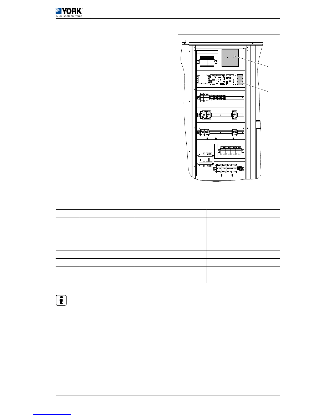
4. Fit the temperature/smoke control board in the electrical box.
NOTE
If the temperature detection accessory is also fitted, a temperature/smoke control board is fitted and
the two normally closed contacts fitted in series in input J4.
5. Connect the cables supplied according to the wiring diagram.
6. Once all of the connections are made, reconnect the unit main switch.
7. Check that the green LED on board A9 remains lit. Next, search and configure the accessories by
pressing the test button on the YKN2Open board (A1) for more than three seconds, until the red
LED lights up. When the search and configuration process starts, the red LED on the board will light
up and will remain on until the operation is completed. Once it has switched off, check that the green
LED (V1) on board A9 is flashing to indicate that the accessory has been configured.
8. To check the electrical operation, disconnect the wires of terminals J4 on board A9 or apply smoke
directly to the optical sensor and check that the YKN2Open board (A1) indicates the high temperature
fault with a 4-5 flashing sequence of the red LED. Reconnect the wires and reset the YKN2Open (A1)
board to delete the fault.
CAUTION
Loose connection terminals produce overheating of cables and terminals. The unit will work incorrectly
and there is a risk of fire.
Data and measurements subject to changes without prior notice.
1 Smoke detector
1.6 Installation
8

1.6.2 Wiring diagram
I
A B C D E
G
F
H2
L1 OUT
L2
L1 IN
J1
2
5
1
J2
I-2453e
H1
A. Green LED. I. Power cables.
B. Reset. 1. A-Green.
C. Battery test. 2. Blue.
D. Remote reset. 3. Black.
E. Coil. J1. Connection cables.
F. Connect red wire to terminal +. L1 OUT: Brown.
G. Accessories. L2: White.
H1. APOLLO sensor. L1 IN: Red.
H2. Sensor C. Scan O J2. Connection cables.
2.: Brown
5: White
1: Red
NOTE
Bear in mind the current regulations on electrical installation in the country where the unit is to be
installed.
Smoke detector 1
Installation 1.6
9
This manual suits for next models
1
Table of contents