Yoshitake SW-10 User manual

■
EPDT-002f
■
Model SW-10,10S
Strainer
Installation &Operation Manual
We thank you very much for using the Yoshitake Products. In order to put in use our
product correctly and safely, please make sure to read this manual thoroughly prior to
the installation. Also we kindly request you to keep this manual with care at your hand.
The following safety sym ols are used in this manual.
Warning
Indicates that mishandling this product might cause fatal or
serious odily injury.
Caution
Indicates that mishandling this product might cause odily
injury or material damage.
Cotents
Overview・・・・・・・・・・・・・・・・・・・・・・・・・・・・1
1.Features・・・・・・・・・・・・・・・・・・・・・・・・・・1
2.Specifications and Performance
2.1Specification・・・・・・・・・・・・・・・・・・・・・1
2.2Dimensions and Weights・・・・・・・・・・・・2
3.Selection of pipe diameter・・・・・・・・・・・・・・3
4.Installation
4.1Example of piping・・・・・・・・・・・・・・・・3
4.2Precautions during installation
and inspection・・・・・・・4
5.Operation
5.1Warning and caution upon operation・・4
5.2Operation method・・・・・・・・・・・・・・5
6. Maintenance Procedure
6.1Trou leshooting・・・・・・・・・・・・・・・・・6
6.2Warning and caution upon inspection・6
7.Assem ly after disassem ly・・・・・・・・・・・・7
8.Exploded drawing・・・・・・・・・・・・・・・・・・・・8

- 1 -
■
EPDT-002f
■
Overview
Used in wide range of purpose as dust removing from water and oil. Mainly used for
cooling water and water for industrial use.
1.Features
(1)By switching the cook,the screen can e washed with out stopping the flow of fluid.
(2)Cock-lift mechanism(lift the cock and switch)makes cock operation smooth and holds
securely the cock.
(3)No need y-pass piping. Thus the piping space is small.
(4)This marine type strainer has a large filtering area which allows sufficient amount of
flow wven when the screen is clogged.
(5)Strainer cover is easily remova le just y taking off a olt(SW-10S).Means easy
maintenance.
2.Specifications and Performance
2.1 Specification
A p p l i c a t i o n Water・Oil・non-corrosive fluid
M a x . P r e s s . 1.0MPa
M a x . T e m p . 80℃
B o d y Ductile Cast iron
C o c k Staineless Steel
Material
S c r e e n Staineless Steel
C o n n e c t i o n JIS 10K FF flange
●Strainers are also availa le made of Stailess Steel(SCS13).
●Standard Strainer Screens are 60 mesh with stainless Steel(φ6-1.42holes/cm
2
).
※Screen from 20 to 250 mesh are also availa le.
●There may e some accepta le range of leakage since the cock is metal seal.
Caution
( 1 ) Please confirm that the indication on the product plate coincidewith the
specifications of the orderdmodel.Alsoconfirm that the condition for usage
coincide with thespecifications.(In the chart a ove)
※In case theydo not coincide,do not usethe product and contact us.

- 2 -
■
EPDT-002f
■
2.2 Dimensions and Weights
No.
Parts of Name
1 Body
2 Cock
3 Gland Cover
4 Adjusting crew
5 Washer
6 Washer of Packing
7 U-Packing
8 Packing Case
9 Gasket
10
Gasket
11
Bolt
12
Pin
13
Cap
14
Gasket
15
Handle
16
topper
17
Bolt
18
pring Lock Washer
19
Gasket
20
creen Case
21
Cover
22
creen
23
Plug
Gasket ( W-10)
24
O-Ring ( W-10 )
tud Bolt( W-10)
25
Arm ( W-10 )
Nut ( W-10)
26
Bolt ( W-10 )
27
Plate
●Model SW-10
●Model SW-10S
28
Driving crew
(mm)
Anchor Bace Weight(kg)
Size
L
L
1
L
2
H
1
H
Ha
A
l ds ls
J
K
h
1
T
1
Plug
SW-10
SW-10S
20A
200
100 100 126
280
294
363
180
64.5
108
135
248
12
14
R 3/4
23.9
26.7
25A
200
100 100 126
280
294
363
180
64.5
108
135
248
12
14
R 3/4
25.1
27.9
32A
205
102.5
102.5
126
280
294
363
180
64.5
108
135
248
12
14
R 3/4
26.1
28.9
40A
245
122.5
122.5
134
306
319
390
180
64.5
120
135
275
12
14
R 3/4
34.0
36.8
50A
245
122.5
122.5
134
306
319
390
180
64.5
120
135
275
12
14
R 3/4
35.9
38.7
65A
285
130 155 155
356
350
450
240
77 140
160
311
15
20
R 3/4
52.5
54.6
80A
285
130 155 155
356
350
450
240
77 140
160
311
15
20
R 3/4
53.0
55.1
100A
385
175 210 230
482
513
644
340
120 210
225
430
19
20
R 1 117.0
124.3
Plugs of R 3/4 are used for stainless steel strainers of all sizes.

- 3 -
■
EPDT-002f
■
H
3.Selection of pipe diameter
When selecting the nominal diameter of pipe, it is necessary to consider the kind of
fluid, its maximum flow rate, allowa le pressure loss and piping installation cost among
others. Smaller diameter of pipe makes the lower piping cost, ut the pressure loss will
e increased and there are possi ilities of a rasion of pipe, noise and vi ration due to
tur ulent flow. If the pipe diameter is too large, not only the piping cost ut also the
heat loss will e increased.
As one method of selection of suita le pipe diameter, Japan Industrial Standard (JIS)
sets the standard flow velocity depends on the relative kind of fluid, its characteristic
and pipe diameter, to which please refer.
≪Standard flow velocity of fluid≫
Fluid Standard flow velocity
Water ,Oil 2 m/s(2~4)
※This list shows the standard flow velocity of relative fluid, which made in reference with
the standard of JIS F7101(Ship’s Machinery Standard Flow Velocity in Pipes).
Screen: φ6-1.42holes/cm
2
Element 60mesh
Fluid
:
Water
【Figure1】Pressure loss
4.Installation
4.1 Example of piping
【
Figure2
】 【
Figure3
】
(mm)
ize 20~32A 40・50A 65・80A 100A
H 200以上 250以上 300以上

- 4 -
■
EPDT-002f
■
4.2 Precautions during installation and inspection
Caution
(1)Please confirm that the direction of the fluid flow and the arrow on the product
coincide efore installing the product.
※The product will not function if it is installed in the wrong direction.
(2)Please support the piping and fix on the product securely.
※The product may deform y too much stress from the piping.
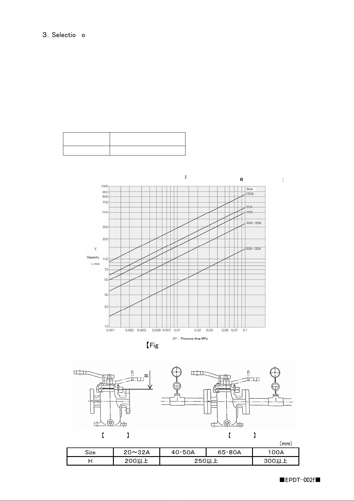
(3)Upon installation, please secure sufficient space as shown in 〔4.1 Example of
piping 【 Figure2 】 〕 for maintenance and inspection (including cleaning of the
screen).
※You will e una le to maintain (including cleaning of the screen) and inspect
the product if there is not enough space.
(4)Upon piping, please make sure that U
nnatural force, ending,or vi ration will not e
transmitted to the products.
※In adequate piping can result in leakage.
(5)Please make sure that the connections with the piping are secure.
※Inadequate connections can result in physical damages due to fluid outflow
caused y vi rations and other reasons.
※Inadequate connections can result in fluid outflow.
(1)Installiing pressure gauges at inlet and outlet side may help to detect the clogging
upof the screen.〔4.1 Example of piping【Figure3】〕
(2)When using at outside,painting is needed to avoid from the rust.
5.Operation
5.1 Warning and caution upon operation
Warning
(1)Please make sure that there is no danger at the pipe end efore pouring the fluid.
※You may get scalded in case hot fluid spouts out.
※Physical damage may occur from fluid outflow.
Caution
(1)Use the strainer in condition of maximum pressure loss of elow 0.1MPa.Also
keep cleaning the screen periodically.
※The Screen may e damaged.
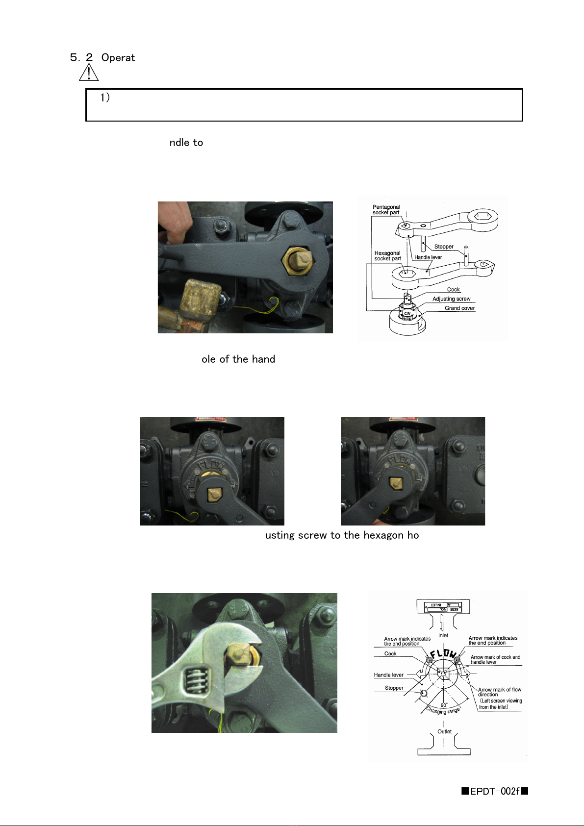
(2)Always follow the sequence when switching the cock.
※The product may not work properly.〔5.2 Operation method Reference〕
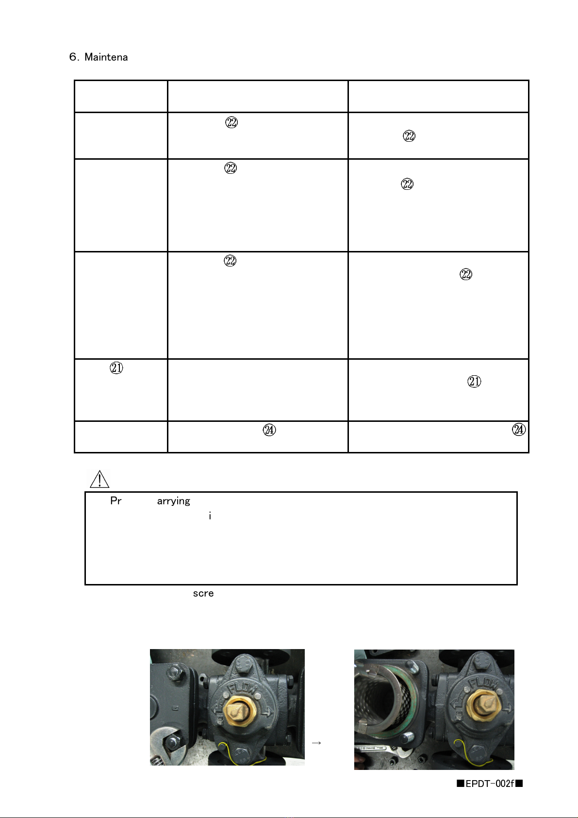
(3)
There are some allowa le leakages from the cock, so when cleaning the screen,
please take off
the plug under the screen case,and install the low valve to
release the fluid to the safety place.
(1)When cock and adjusting screw trun at the same time, please fix the cock with
wrench and turn the adjusting screw.
※May not o tain the proper pressure drop or filtration a ility.
(2)Do not tighten the adjusting screw with excessive torque.
※It may cause the reakage on cock and sdjusting screw.

- 5 -
■
EPDT-002f
■
5.2 Operation method
Caution
(1) While switching the cock, e sure to operate in the following order.
※Pull up the cock in order not to reak if while switching.
(1)Fit the handle to hexagonal adjusting screw and turn clockwise to unlock.It may e
hard to do so ecause the cock and adjusting screw are tightened together.In this
case,hammer the handle with plastic hammer.(Do not use iron hammer)Turn the
adjusting screw clockwise one or two times to haul up the cock.
(2)Fit the square hole of the handle to the cock.(Stopper is facing downward)and
switch the cock right or left.Match the arrows on the cock and handle with the
arrow end on the screen side to e used.Turn until the handle stops y the
stopper.
→
(3)After switching,install the adjusting screw to the hexagon hole on the handle
andturn clockwise.When cock and adjusting screw turn at the same time,please fix
the one side with the wrench.Please tighten the adjusting screw with provided
handle.

- 6 -
■
EPDT-002f
■
6.Maintenance Procedure
6.1 Trou leshooting
Trou le
Condition
Cause of trou le Countermeasure and remedy
No fluid flows.
1.Screen is clogged up.
2.Stop valves at inlet and/or
outlet side are shut.
1.Disassem le and clean the
Screen .
2.Open the stop valve.
Pressure loss is
excessive.
1.Screen is clogged up.
2.Pressur gauge is damaged.
3.The nominal size is too small
for the actual flow volume.
1.Disassem le and clean the
screen .
2.Renew the Pressure gauge.
3.Use a strainer with alarger
nominal size.
〔【Figure1】Loss of Pressure〕
Alien matter is
not removed.
1.Screen is damaged.
1.Disassem le the strainer and
exchange screen .In case
quick valves are installed at
either at end of the strainer,
do not open them immediately
since this may result in
damage of the water hammer.
Cover can not
e removed
upon exchange
of screen.
1.The inside of the product is
vacuum.
1.Break the vacuum inside the
pipe and remove cover .
Outer leakage
occurs.
1.Gasket・O-ring is damaged. 1.Install a new Gasket・O-Ring
6.2 Warning and caution upon inspection
Warning
(1)Prior to
carrying out the maintenance and inspection,make sure the pressure inside
of the strainer or piping system go down to the atmosphere pressure,also in case
the high temperature of fluid is applied, leave the system cooled down until you
can handle them with are hands.
※
The remaining pressure inside the strainer or piping system may cause the
personnel injured or eing scaled.
(1)When cleaning the screen,check the arrow and make sure that fluid is not passing.
Open the cap which the fluide is not passing through,take out the screen,and clean with
compressed air and cleaning agent.
※Do not take out the screen y force when screen is stuck.(Screen handle might e
damaged.)
→

- 7 -
■
EPDT-002f
■
7.Assem ly after disassem ly
●Model SW-10
Caution
(1)
Clean up the seating surface of gasket on the ody and cover, or sealing portion of
O-ring.
※Insufficient cleaning can result in outer leakage and injuries or scalding.
(2)Use a new gasket at assem ly.
※Used gasket may result in outer leakage.
(1)Clean the gasket contacting surface of the Screen case and cover. Attach a new
gasket to the cover.
(2)Put a cleaned screen into the screen case and attack the cover. Tighten the hex nut.
●Model SW-10S
Caution
(1)Clean the contacting surface of the screen case and cover.Make sure that O-
ring is
attached properly.
※If the O-ring is not installed properly,O-
ring may e damaged and can e result
inouter leakage.
(2)In case O-ring is damaged or deteriorated, change to new o-
ring and apply the grease
on it.
※There is a possi ility of leakage in case o-ring is damaged or deteriorated.
(1)Clean the gasket contacting surface of the Screen case and cover. Attach a new
gasket to the cover.
(2)Put a cleaned screen into the screen case and attack the cover. Tighten the hex olt.

- 8 -
■
EPDT-002f
■
8.Exploded drawing
●ModelSW-10(The structure for ModelSW-10S is a different.)
Name of Parts Exchange time
Gasket At resolution
Washer
Other manuals for SW-10
1
This manual suits for next models
1
Popular Kitchen Appliance manuals by other brands

Silvercrest
Silvercrest SMA 3 B1 operating instructions

Smartplanet
Smartplanet MDM-1W instruction manual

Goldmedal
Goldmedal 2174EL/ER instruction manual

Goldmedal
Goldmedal 1866 instruction manual

Silvercrest
Silvercrest SAS 150 A1 Operation and safety notes

Range Master
Range Master Elan 90 Dual Fuel user guide