Yoshitake MD-71 User manual

■EPDT-201g■
Water receiving tank and high placement water tank application
Emergency shut-off system
Type MD-71 Emergency shut-off valve
Type KS-5 Emergency shut-off valve control panel
Operation manual
Thank you very much for purchasing this product from Yoshitake. To use the purchased product on a
correct and safe basis, read this text before using it. In addition, the user customer is to store this
document carefully.
Responsibility for a failure of the product caused by improper handling will be assumed by the customer.
In this case, the product will be replaced or repaired at the customer's expense.
----- Symbols used in this text refer to the following: -----
Warning Improper handling may cause the user to be killed or seriously injured
Caution Improper handling may cause the user to be slightly injured or the
equipment to be damaged
Table of contents
1. Product application ····················································································1
2. Specifications
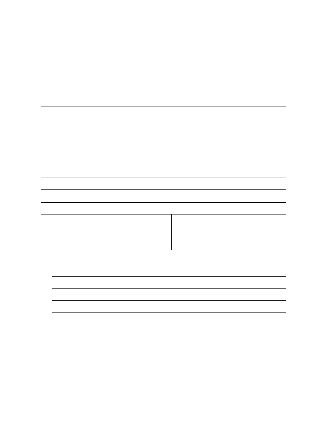
2.1 Specifications for the emergency shut-off valve ····································1
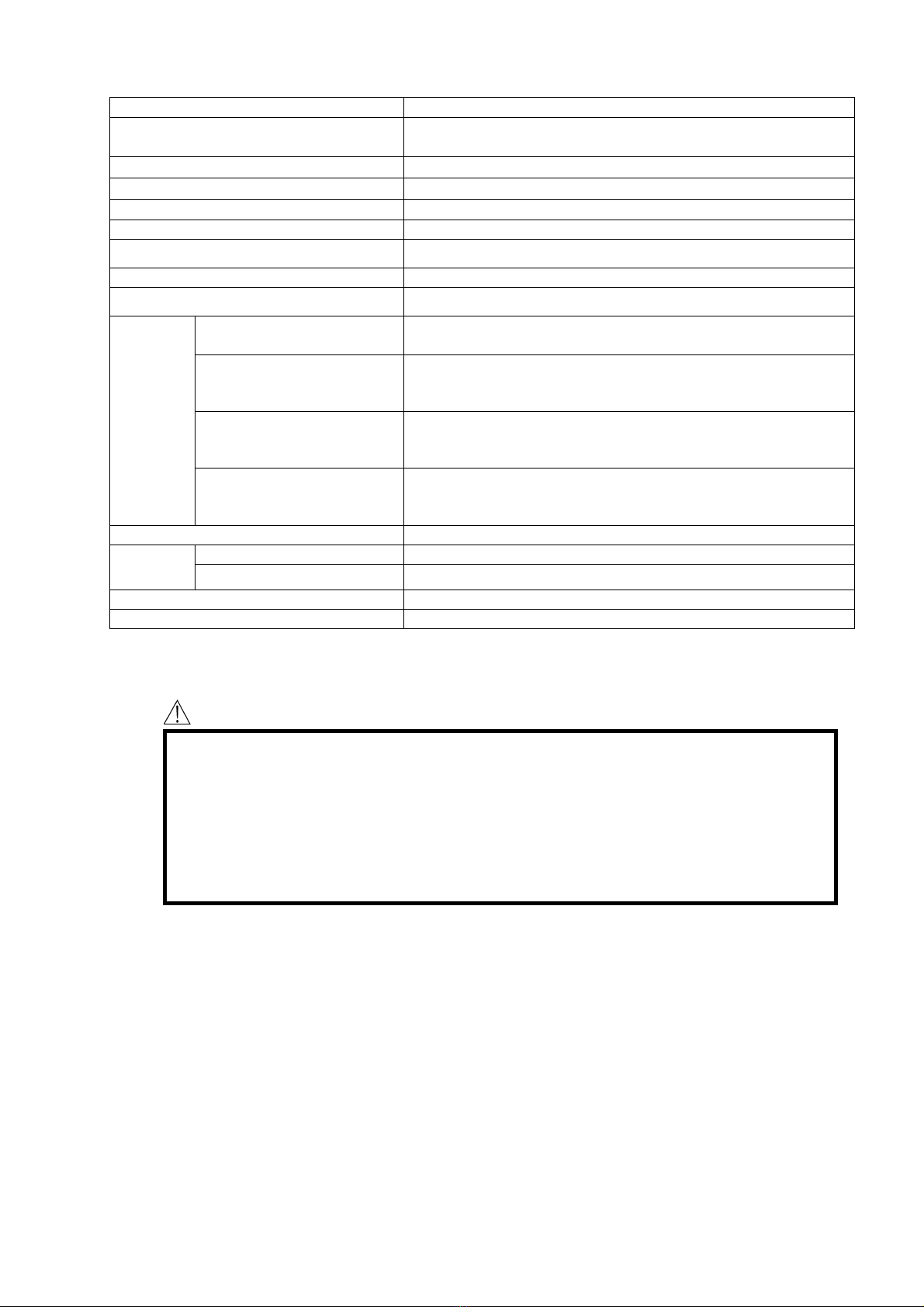
2.2 Specifications for the emergency shut-off valve control panel ···············2
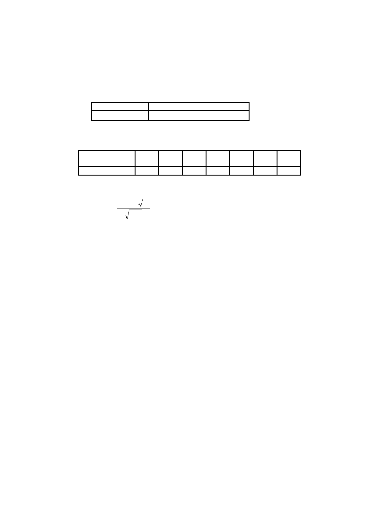
3. Nominal diameter selection··········································································3
4. Dimensions, weight, and structure
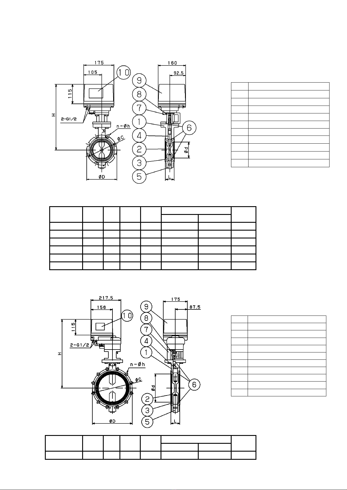
4.1 Emergency shut-off valve ······································································4
4.2 Emergency shut-off valve control panel ················································5
5. Operational description
5.1 Normal condition·····················································································5
5.2 In the case of an earthquake···································································6
5.3 Recovery work························································································6
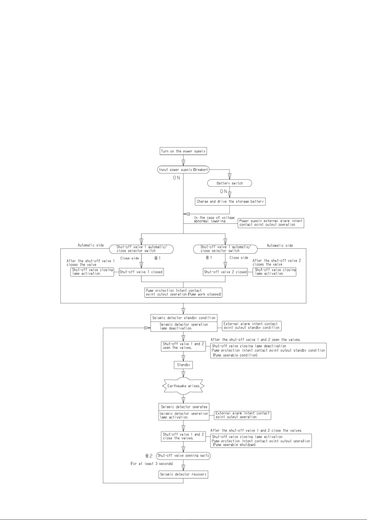
6. Process flowchart ························································································6
7. Installation procedure
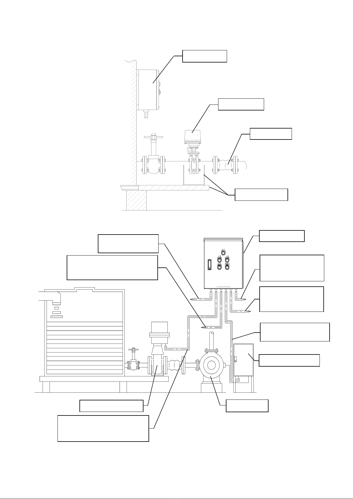
7.1 Sample piping diagram ···········································································7
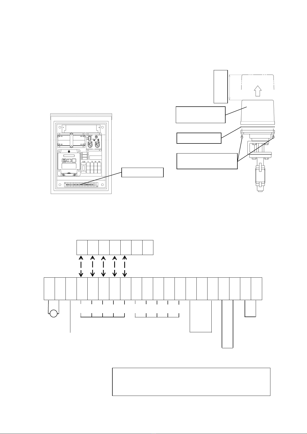
7.2 Shut-off valve and control panel connection diagram·······················8 to 9
7.3 Warnings and cautions in installing the product ···························10 to 12
7.4 How to adjust the seismic detector ·············································· 12 to 13
8. Operation procedure
8.1 Warnings in operation ········································································· 14
8.2 Trial running··············································································· 14 to 17
9. Maintenance procedure
9.1 Malfunctions and troubleshooting ················································18 to 19
9.2 Warnings and cautions in maintenance and inspection ························19
9.3 Periodic inspection····································································· 19 to 21
9.4 Manual operation method ·························································· 21 to 22
About after-sales service

-1- ■EPDT-201g■
1. Product application
If an earthquake disaster arises to break the pipe line, precious water for living stored in the water
receiving tank or high placement water tank will outflow. After the disaster, lifelines must therefore be
prevented from discontinuing to secure water for living.
This product is an emergency shut-off system intended to secure water in the water receiving tank and
the high placement water tank.
2. Specifications
2.1 Specifications for the emergency shut-off valve
Model Type MD-71 (butterfly valve)
Nominal diameter 50~200A
Connection Geometry Wafer shape
Type JIS 10 K
Applicable fluid Tap water
Maximum usable pressure 1.0MPa
Fluid temperature 5~60℃
Installation posture Installed from square to lateral direction to a horizontal pipe
line
Switching time 4 seconds or less
Main body FCD450 or FC300
Primary portion material Valve body SCS14 or SUS F 316
Seat FKM
Electric actuator
Rated voltage DC24V
Power consumption 50~100A:MAX. 80VA
125~200A:MAX 120VA
Ambient temperature -20 to 55°C (no frost allowed)
Motor protection Current limiter type
Measure for dew condensation Space heater built in
Manual operation Manual operation mechanism incorporated
Protective structure Rain-proof type
Electric wire incoming port G1/2
●Available with the MD-71-N, complying with the Water Works Law in Japan.

-2- ■EPDT-201g■
2.2 Specifications for the emergency shut-off valve control panel
Model Type KS-5
Emergencyshut-off valve
control unit quantity (*1) Two units
Inputpower supply AC85~240V 50/60Hz
Ambient temperature -10~50℃
Backuppower supply DC24V
Backup time Approximately 5 hours
Storage battery Made by Japan Battery Cells (PE 12 V 2.2)
Charge strategy Constant charge strategy (float charge)
Measurefor lightning damage Surge absorber incorporated
Output
terminal
Emergency shut-off
valve control intent DC24V
Pump protection intent
(*2) No voltage contact point c (1c)
Seismicdetector
External alarm
intent
No voltage contact point a (1a) (ON contact point with the
seismic detector in operation)
Power supply
external alarm
intent
No voltage contact point a (1a) (ON contact point in the
case of a power supply drop fault in the control panel)
Shut-off valve opening switch Shut-off valve opening switch
Seismic
detector Detection direction All horizontal directions
Set acceleration 200 gal (equivalent to a seismic intensity of 5)
Installation site Indoor or outdoor (equivalent to JIS C0920 IP44)
Mount strategy Wall hanging type
*1: Those for controlling 1 unit, 3 units, and 4 units can be produced as well.
*2: Those for controlling 3 units and 4 units differ.
Caution
(1)Check the indication contents of the label (emergency shut-off valve shut-off valve
control panel door back side) attached to the product and the specification contents of
the type ordered.
*If the contents are inconsistent, do not use it and contact our company.
(2)Replace the storage battery cells every three years.
*If they are not replaced, the unit can possibly fail in starting up in the case of a power
failure.

-3- ■EPDT-201g■
3.Nominal diameter selection
Select one with a nominal diameter equivalent to or more than the suction (suck) side of the pump.
If one with a smaller nominal diameter is used, the specified flow rate cannot be maintained in some
cases. (The following figure shows the Cv value and calculating formula).
If the nominal diameter of the piping is selected, refer to the standard flow rate specified by the
Japanese Industrial Standards (JIS) as an appropriate piping nominal diameter selection
method.
Standard flow rate of the fluid
Fluid Standard flow rate
Water or oil 2 m/s ( 2~4)
*This table shows the standard flow rate created with reference to the specifications of JIS F7101
(standard flow rates in the pipe lines of the seacraft engine units).
·Cv value of the emergency shut-off valve
Nominal
diameter 50A 65A 80A 100A 125A 150A 200A
Cv value 159 266 457 860 1320 2020 3540
·Cv value calculating formula
Cv VG
P
=0365.
⊿
P1 :P1: Primary side pressure (MPa·A) V:Maximum fluid flow rate (m3/h)
P2 :Secondary side pressure (MPa·A) Cv: Cv value of each nominal diameter
ΔP : P1-P2(MPa)
G : Specific gravity (specific gravity to water)

-4- ■EPDT-201g■
4.Dimensions, weight, and structure
4.1 Emergency shut-off valve (hereafter called the "shut-off valve")
4.1.1 Nominal diameters of 50 to 150 A
No. Part name
1 Main body
2 Valve body
3 Seat
4Stem
5Pin
6 O-ring
7 Bracket
8 Connector
9 Electric actuator
10 Label
(mm)
Nominal
diameter d L D H
JIS 10K(Wafer shape) Weight
(kg)
C n - h
50A 52 41 102 332 120 4-19 7.7
65A 64 44 135 349 140 4-19 9.2
80A 78 44 145 356 150 8-19 9.7
100A 103 51 175 384 175 8-19 12
125A 129 54 206 406 210 8-23 15
150A 154 54 231 419 240 8-23 16
4.1.2 Nominal diameter of 200 A
No. Part name
1 Main body
2 Valve body
3 Seat
4Stem
5Pin
6 O-ring
7 Bracket
8 Connector
9 Electric actuator
10 Label
(mm)
Nominal
diameter d L D H
JIS 10K(Wafer shape) Weight
(kg)
C n-h
200A 200 60 256 501 290 12-23 30

-5- ■EPDT-201g■
4.2 Emergency shut-off valve control panel (hereafter called the "control panel")
*Those for controlling 1 unit, 3 units, and 4 units differ.
No. Part name Function
1 Power supply lamp (white) When the breaker and battery switch is turned on, this comes on.
2 Seismic detector operation
lamp (orange) When the seismic detector starts working, this comes on.
3 Shut-off valve opening switch
(Yellow)
When the seismic detector is in operation with the shut-off valve
closed, this operates to open the shut-off valve. When the switch is
pressed (3 seconds or more), the seismic detector restores and also
the shut-off valve opens the valve.
4 Shut-off valve closing switch (red)
The seismic detector starts working and the shut-off valve closes the
valve and then the lamp comes on. Deactivation in general.
5 Breaker "ON" and "OFF" of the input power supply is changed over.
7 Power supply equipment The input power supply is converted into 24 V DC.
8 In-charging lamp When the breaker is turned on, this comes on.
9 Battery switch When the switch is turned on, the storage battery starts charging.
Turn this on in general.
10 In-backup lamp When the battery switch is turned on, this comes on.
11 Storage battery In the case of a power failure, this becomes the power supply.
12 Fuse When an over current flows, this shuts off to protect the circuit.
14 Seismic detector When the set acceleration is exceeded, this starts working.
15 Shut-off valve
automatic/close selector switch In general, this is set to "automatic." When a changeover to "close" is
made, the shut-off valve closes the valve.
18 Terminal block This table is to connect to the shut-off valve.
5. Operational description (Refer to "4.2 Control panel")
5.1 Normal condition
In general, the shut-off valve is in a valve opening condition and only the power supply lamp ①of
the control panel is turned on.
(To make a switching operation with the shut-off valve in normal condition, a switching
operation is available by operating the shut-off valve automatic/close selector switch ⑮of the
control panel. Also, see "6.Process flowchart *1")).
Holder(Side in board)
Manual insertion
Water drain port
(with cap)
Weight: 26 kg
Panel mount
hole

-6- ■EPDT-201g■
5.2 In the case of an earthquake
If the seismic detector ⑭mounted inside the control panel detects an earthquake (equivalent
to a seismic intensity of 5), the shut-off valve automatically closes the valve. At this time, the
seismic detector operation lamp ②on the panel surface and the shut-off valve closing lamp
④come on.
5.3 Recovery work
If the shut-off valve closes the valve in the case of an earthquake, make sure that no fault of
the piping is found and then press the shut-off valve opening switch ③(for at least 3
seconds) to reset the seismic detector ⑭to "open" the shut-off valve. At this time, the
seismic detector operation lamp ②and shut-off valve closing lamp ④on the panel surface
go off. ("6.Process flowchart": *2)
6.Process flowchart (for controlling two units)

-7- ■EPDT-201g■
7.Installation procedure
7.1 Sample piping diagram
*The other shut-off valves for controlling 3 units and 4 units are the same as the No.1 and No.2 (the
others are the same as well).
Control panel
Shut-off valve
Flexible
Support
Water receiving tank
or
hi
g
h
p
lacement water
Shut-off valve No.1
25m or less 1.25mm2x 5 cores
50m or less 2.00mm2x 5 cores
Shut-off valve No.2
25m or less 1.25mm2x 5 cores
50m or less 2.00mm2x 5 cores
Control
p
anel
t
IInput power supply
2.00mm2×3cores
Pump control panel
Lifting pump
Shut-off valve No.1
Pump protection intent
2.00mm2×2cores
Seismic detector
external alarm intent
2.00mm2×2cores
Power supply
external alarm intent
2.00mm2×2cores
Water receivin
g
tank

-8- ■EPDT-201g■
7.2 Shut-off valve and control panel connection diagram
This section describes where the shut-off valves and each terminal block of the control panel are
installed.
(1)Control panel terminal block (figure 1)
The terminal block is located inside the control panel.
(2)Shut-off valve terminal block (figure 2)
The terminal block is located inside the electric actuator.
Remove the hexagon socket head bolts to remove
the electric actuator cover.
Figure 1 Figure 2
XO
YO
E
X
Y
11
X
12
X
Y
14
X
15
COM
NC
NO
A1
A2
B1
B2
Pump protection intent : No voltage contact point c
Seismic detector external alarm intent : No voltage contact point a
Power supply external alarm intent : No voltage contact point a
Inside the control panel
(
without the front door
)
Terminal block
Electric actuator
cover
Rubber packing
120mm or more
Hexagon socket head
bolts
(
at four locations
)
Ground
Shut-off valve No.1 Shut-off valve No.2
Pump protection intent
(※1)
Seismic detector
external alarm intent
(
※2
)
T1 T2 O SC SS
~ T1 T2 O SC SS
Power supply
external alarm intent
(
※
3
)
Input power
supply
Terminal block inside
the control
p
anel
Terminal block inside
the electric actuator
(shut-off valve No.1) *Connect the shut-off valve No.2
in the same manner.
T1
T2
O
SC
SS
SO
AL

-9- ■EPDT-201g■
※1 Pump protection intent : It is an output terminal for the pump idling prevention with the close valve of
the cutoff valve.(No voltage contact point c:for controlling two units)
Please select NC or NO together and connect COM.
NC : The point of contact opens after the close valve of the
shut-off valve.
NO : The point of contact shuts after the close valve of the
shut-off valve.
※2 Seismic detector external alarm intent : It is an output terminal when the seismic detector works.
(No voltage contact point a : The point of contact shuts after the seismic sensor works.)
(Cautions) It enters the state of the output even if there is no power
supply.(The point of contact shuts)
※3 Power supply external alarm intent : It is an output terminal for no supply of electricity from the power
supply and the storage battery.
(No voltage contact point a : The point of contact shuts when electricity is not supplied
from the power supply and the storage battery.)

-10- ■EPDT-201g■
7.3 Warnings and cautions in installing the product
7.3.1 Warnings and cautions with the control panel and shut-off valves
Warnings
(1)Since the control panel and the shut-off valves are heavy weights, use a hoisting device or
an equivalent to definitely support the product when installing them.
*A drop can possibly cause an injury.
*A drop can possibly damage a function.
(2)The control panel and the shut-off valves do not have an explosion-proof structure. Avoid
using the unit in the atmosphere of corrosive gas or volatile gas, in an accumulation place, or
in an explosive atmosphere.
(3)Allow a skilled and specialized worker to implement the construction of electric wiring.
(4)Before connection, make sure that the power supply is not turned on.
*The operator can get an electric shock.
(5)Before connection, check the rated voltage and conduct it appropriately according to the
connection instructions. (Also, see page 8).
*Improper connection can possibly cause an electric shock or fire.
*If used with any other than the specified power supply, the unit can possibly generate
smoke or fire.
(6)For the connected portion, ensure to adopt definite insulation treatment measures.
*Insufficient treatment can possibly cause an electric shock or fire.
(7)If the unit is used outdoors, adopt waterproof measures on the connected portion.
*A short circuit can possibly occur.
(8)Make sure that the control panel and the electric operator interior are free from water
intrusion.
*An electric shock can possibly be given.
(9)Avoid access to the terminal portion and connected portion out of the connection work.
*An electric shock can possibly be given.
(10)Connect the pump protection intent output terminal and the pump intent control panel
(interlock terminal inside the pump intent control panel) in such a manner that the pump will
definitely stop running when the shut-off valve closes the valve.
*The pump can possibly idle without water supply to the pump inlet side to burn out the
motor, resulting in a pump failure or fire.
(11)Do not remove the electric actuator from the shut-off valve bodies when connecting the
shut-off valves to the piping
* This can possibly cause loss of parts or a malfunction.
Cautions
(1)Avoid disassembling the control panel and the shut-off valves.
*Careless disassembly prevents the product from functioning.
(2)Use the electric wire material as specified in "7.1 Sample piping diagram."
In addition, make sure that the wiring is free from an unreasonable force.
(3)If the unit is used outdoors, avoid connecting the lines in a rain.
*An electric shock can possibly be given.
(4)Note that the maximum wiring distance between the control panel and the shut-off valves is
50 meters.
*If the wiring distance exceeds 50 meters, the shut-off valves can possibly fail in working.
(1)When wireways or Prica tubes are used, they must fully be sealed so that no rain water
would intrude or dew condensation will not result.
(2)Adopt electric shock preventive measures such as grounding.

-11- ■EPDT-201g■
7.3.2 Cautions with the control panel
Cautions
(1)Make sure that the control panel installed is free from vibration.
*Vibration or an equivalent can possibly cause a malfunction.
(2)When installing the control panel, reserve sufficient space for maintenance, inspection, and
repair.
(3)Avoid installing the control panel in a floodable place.
(4)Install the control panel definitely on a water tank wall surface or wall.
(5)Please do not give a shock to internal parts.
Please do not give a shock to internal parts.

-12- ■EPDT-201g■
7.3.3 Cautions with the shut-off valves
Cautions
(1)When piping the shut-off valves, ensure to remove the foreign material out of the pipes.
*If foreign materials or scales intrude the shut-off valves, the original performance will not be
utilized.
(2)In installing the shut-off valves, reserve sufficient space for maintenance,
inspection, and repair. (Over the electric actuator: 120 mm or more) (See page 8).
(3)Check the installation posture of the shut-off valve to install it. (See the following figure).
(Use a square to lateral direction but avoid an upside-down state).
(4)If the fluid or driving unit can possibly freeze, adopt frost preventive measures.
*The function of the shut-off valve can possibly be degraded.
(5)To prevent unreasonable force, curvature, or vibration from being transmitted to the shut-off
valve, install a support platform. (See the "7.1 Sample piping diagram").
*The shut-off valve can possibly malfunction or the service life can possibly be shortened.
(6)To the secondary side of the shut-off valve, connect a flexible fitting such as a flexible joint.
*An earthquake can possibly damage the piping for the fluid to outflow, resulting in physical
damage.
(7)On the seat surface of the shut-off valve (FKM), make sure that no machining oil or mineral
concerned grease is applied.
*The function of the product can possibly be damaged.
(1)In piping work, prevent water, sand, or dust from intruding into the electric actuator.
(2)Accurately center align the connection flange and the shut-off valve to prevent the valve body
from coming in contact with the inside of the pipe.
(3)If the valve body can possibly come in contact with the inside of the pipe, chamfer the pipe
connection inner circumference.
(4)When connecting the shut-off valve, avoid using a flange gasket.
(This does not apply to some special parts).
(5)Regarding bolt tightening, tighten it with a uniform force alternately on the diagonal.
(6)In installing the shut-off valve, keep the delivery condition (with the valve body opening by 3
or 5 %) to install it directly.
(7)If radiated heat causes surface temperature of the electric actuator cover to exceed 55°C,
install appropriate shield plates.
(8)Find two electric wire incoming ports of G1/2 below the electric actuator. Since an electric
wire connector (cabtire cable intent) and a plug are attached as attachments, use them if
required.
(9)For wiring work, remove the electric actuator cover.
(10)In wiring to the electric actuator, use an appropriate cabtire cable (φ6 to φ12) to fully seal it.
To the cut cross section of the cable, apply a filling agent to completely adopt measures for
dew condensation.
(11)If a sealant is used inside the electric actuator, use one for electric devices not adversely
affecting the contact points such as limit switches.
(12)Since no water intrudes from the outside after connection, install the rubber packing and
then definitely tighten the electric actuator cover with hexagon socket head bolts. (Also, see
page 7).

-13- ■EPDT-201g■
(13)Regarding the bolt insertion position in installing the shut-off valve to the piping, see the
following figure to insert the bolt for easy installation work:
7.4 How to adjust the seismic detector
After installing the control panel, adjust the seismic detector in the following procedure. (See the
following figure). For the seismic detector mounted inside the control panel, the level protractor
must be adjusted. (Do not turn on the breaker and the battery switch).
(1)Loosen the main body cover mount screw ①and remove the main body cover ②close to you.
(2)To slightly touch the level protractor (bead chain) ③to touch the reference hole ④, conduct the
process from (3) to (9).
In addition, if the level protractor (bead chain the level protractor adjustment intent lock nut ⑤and
the level protractor adjustment intent screw ⑧to conduct the process from (7) to (9).
(3)Loosen the level protractor adjustment intent screw ⑧and the level protractor adjustment intent
lock nut ⑤. ) ③is not in contact with the reference hole ④, definitely tighten
(4)By loosening or closing up the level protractor adjustment intent nut ⑦, move the adjustment plate
⑨in the back-and-forth direction, position the level protractor adjustment intent nut ⑦so that the
level protractor (bead chain) ③will not come in contact with the reference hole ④, and
temporarily retain the level protractor adjustment intent lock nut ⑤. Next, move the adjustment
plate ⑨left and right, position the unit so that the level protractor (bead chain) ③will not come in
contact with the reference hole ④, and then temporarily retain the level protractor adjustment
intent screw ⑧.
(5)Make a fine adjustment in such a manner that the level protractor (bead chain) ③comes in the
center of the reference hole ④and definitely tighten the level protractor adjustment intent lock nut
⑤and the level protractor adjustment intent screw ⑧.
(6)Loosen the set value indication plate retention screw ⑪. Move the set value indication plate ⑩
in the back-and-forth direction, align the reference line of the set value indication plate ⑩with the
surface of the adjustment plate ⑨, and tighten the set value indication plate retention screw ⑪.
(7)Cut off the steel ball retention intent stopper (tie wrap band) ⑭with a pair of nippers or an
equivalent and remove the steel ball retention intent stopper (tie wrap band) ⑭. (Since the
sensor portion is protected from vibration or impact when the seismic detector is carried, the steel
ball retention intent stopper (tie wrap band) ⑭is installed.
(8)Raise the lever ⑬slowly up to the uppermost end, set the steel ball ⑮on the receiving rod ⑯,
取付姿勢
Installation
p
osture
bolts

-14- ■EPDT-201g■
and lower it downward. (The operation indicator ⑫of the seismic detector becomes "green.")
(9)Install the main body cover ②and tighten the main body cover mount screw ①.
*The ⑫is the operation indicator of the seismic detector. "Green" refers to standby of the
seismic detector and "red" refers to the seismic detector in operation (with the shut-off valve
closed).
Cautions
(1)Do not use the unit with the level protractor (bead chain) ③in contact with the reference hole
④.
*This will cause a malfunction.
(2)Cut off the steel ball retention intent stopper (tie wrap band) with a pair of nippers or an
equivalent to remove the steel ball retention intent stopper ⑭.
*If the steel ball retention intent stopper ⑭is not removed, the seismic detector does not
operate.
*When the shut-off valve closing switch (see page 5) is pressed without removing the steel ball
retention intent stopper ⑭, the seismic detector can possibly malfunction.
8.Operation procedure
No. Part name
1 Part name
2 Main body cover
mount screw
3 Level protractor
(bead chain)
4 Reference hole
5 Level protractor adjustment
intent lock nut
6 Spring washer
7 Level protractor adjustment
intent nut
8 Level protractor adjustment
intent screw
9 Adjustment plate
10 Set value indication plate
11 Set value indication plate
retention screw
12 Operation indicator
13 Lever
14 Steel ball retention intent
Stopper (Tie wrap band)
15 Steel ball
16 Receiving rod
17 Cotton swab (used in manual
operation: see page 20).
Status with main body cover ②removed
Reference line
Surface of
adjustment
p
late

-15- ■EPDT-201g■
8.1 Warnings in operation
Warnings
(1)Before fluid flows, make sure that no risk is anticipated even when fluid flows to the terminals
of the piping.
*If high temperature fluid blows, a burn can possibly result.
*Physical damage can possibly be caused by a fluid outflow.
(2)Keep the control panel energized at all times.
*If it is not kept energized at all times, no operation will be anticipated in the case of a power
failure.
(1)Since the shut-off valve has a mechanical working portion (connector unit), avoid access to
the moving unit in operation.
(2)Avoid a using method where a reverse rotation signal is input in a switching operation.
*This can shorten the life time of the product.
8.2 Trial running
When a shut-off valve is installed with newly installed piping or replacement or in periodic
inspection, run a trial according to "8.2.2 Trial running procedure."
8.2.1 Check before trial running
Before making a trial, ensure to check the following items:
(1)Make sure that no mistake of the connection and input power supply specifications is found.
(2)Make sure that the steel ball retention intent stopper (tie wrap band) of the seismic detector is
removed. (See (7) of "7.4 How to adjust the seismic detector").
(3)Make sure that the operation indicator of the seismic detector is in "green."
(See (8) of "7.4 How to adjust the seismic detector").
(4)Make sure that the shut-off valve automatic/close selector switch is turned to the
"automatic" side.
Caution
(1)Ensure to make a check before making a trial.
*This can possibly cause a malfunction.
8.2.2 Trial running procedure
To operate the following operation procedure, see "each unit name of '4.2 Control panel' on page 5."
Since it is used for "9.3 Periodic inspection" as well, copy and use it for convenience sake.
Interlock with the pump protection intent and external alarm intent is based on both the two shut-off
valves connected (those for controlling 3 units and 4 units require the unit quantity in the same
manner). No.1 to No.6 are in the operation procedure in series.

-16- ■EPDT-201g■
NO. Item Operation procedure Check contents Judgement
(OK, NG) Measure and action
in the case of NG
1 Check before
trial running
Condition check Make sure that no mistake of
the connection and input
power supply specifications is
found.
As shown on the
connection diagram.
Make sure that the steel ball
retention intent stopper (tie wrap
band) of the seismic detector is
removed.
(See (7) of "7.4 How to adjust the
seismic detector").
Remove the steel
ball retention intent
stopper (tie wrap
band) of the seismic
detector.
(See (7) of "7.4 How
to adjust the seismic
detector").
Make sure that the operation
indicator of the seismic detector
is in "green."
(See (8) of "7.4 How to adjust the
seismic detector").
Turn the operation
indicator of the
seismic detector into
"green."
(See (8) of "7.4 How
to adjust the seismic
detector").
Make sure that the shut-off valve
automatic/close selector switch ⑮
is turned to the "automatic" side.
Turn the selector
switch to the
"automatic" side.
Make sure that the device operate
if connected with the external
alarm intent terminal.
Make a check for
connection and
broken wires.
Make sure that the device
operate if connected with the
power supply external alarm
intent terminal.
2 Turn on the
power supply.
(After
conducting the
operation
procedure
from a to c,
inspect the
check
contents).
a. Connect the input
power supply.
b. Turn on thebreaker
⑤.
c. Turn on the battery
switch ⑨.
Make sure that the power supply
lamp ①is turned on.
Check the input
power supply.
Make sure that the shut-off valve
closing lamp ④is turned off.
Press the shut-off
valve opening
switch ③(for at
least 3 seconds).
Make sure that the seismic
detector operation lamp ②
is turned off.
Make sure that the shut-off valve
opens the valve.
Make a check for
connection and
broken wires.
Make sure that the device doesn'
t operate if connected with the
external alarm intent terminal.
Make sure that the device doesn't
operate if connected with the
power supply external alarm
intent terminal.
d. Make sure that the pump
stops running if connected with
the pump protection intent
terminal.

-17- ■EPDT-201g■
NO. Item Operation procedure Check contents Judgement
(OK, NG) Measure and action
in the case of NG
3 Operation
check
throughmanual
operation
(Interlock with
the pump
requires the
pump in a
running state).
a. Turn the shut-off
valve
automatic/close
selector switch ⑮
to the "close"
side.
a. Make sure that the shut-off
valve closes the valve. Make a check for
connection and
broken wires.
a. Make sure that the shut-off
valve closing lamp ④comes
on.
a. Make sure that the electric
actuator unit does not
make an abnormal noise.
Make a check for
loosened screws or
wear caused
rattling.
b. Turn the shut-off
valve
automatic/close
selector switch ⑮
to the"automatic"
side.
b. Make sure that the shut-off
valve opens the valve. Make a check for
connection and
broken wires.
b. Make sure that the shut-off
valve closing lamp ④goes off.
d. Turn the shut-off
valve
automatic/close
selector switch ⑮
to the "close" side
for both the two
units (those for
controlling 3 units
and 4 units
require the unit
quantity in the
same manner).
d. Make sure that the shut-off
valve closes the valve. Make a check for
connection and
broken wires.
d. Make sure that the shut-off
valve closing lamp ④comes
on.
d. Make sure that the pump
stops running if connected with
the pump protection intent
terminal.
4 Operation
check with the
seismic
detector(Interlo
ck with the
pump requires
the pump in a
running
condition).
a. Condition check a. Make sure that the shut-off
valve automatic/close
selector switch ⑮is turned
to "automatic."
Set it to the
"automatic" side.
a. Make sure that the shut-off
valve opens the valve.
Press the shut-off
valve opening
switch ③(for at
least 3 seconds).
b. Drop a steel ball.
See "9.4 Manual
operation method
and 9.4.1 Seismic
detector."
b.Make sure that the shut-off
valve closes the valve.
Make a check for
connection and
broken wires.
b. Make sure that the shut-off
valve closing lamp ④comes
on.
b. Make sure that the seismic
detector operation lamp ②
comes on.
b. Make sure that the pump
stops running if connected with
the pump protection intent
terminal.
Check the pump for
connection and
broken wires.
b. Make sure that the device
operates if connected with the
external alarm intent terminal.
Make a check for
connection and
broken wires.
c. Press the shut-off
valve opening
switch ③(for at
least 3 seconds).
c. Make sure that the shut-off
valve opens the valve. Make a check for
connection and
broken wires.
c. Make sure that the shut-off
valve closing lamp ④goes off.
c. Make sure that the seismic
detector operation lamp ②
goes off.
c. Make sure that the pump is in a
restartable or startable condition
if connected with the pump
protection intent terminal.
c. Make sure that the device
doesn't operate if connected
with the external alarm intent
terminal.

-18- ■EPDT-201g■
NO. Item Operation procedure Check contents Judgement
(OK, NG) Measure and action
in the case of NG
5 Operation
check in a
power failure
a. Turn off the breaker
⑤to set a power
failure condition to
operate in the same
manner as the
above-mentioned
No.4 "Operation
check with the
seismic detector."
a. Make sure that the "check
contents" of the
above-mentioned No.4 are
fulfilled.
See the
above-mentioned
No.4.
6 Final check
after trial
running(After
conducting the
operation
procedure
from a to b,
inspect the
check
contents).
a. Turn on the breaker
⑤.
b. Turn on the battery
switch ⑨.
Make sure that the input power
supply is energized at all times.
Check the input
power supply.
Make sure that the shut-off valve
automatic/close selector switch ⑮
is turned to "automatic."
Turn it to the
"automatic" side.
Make sure that the shut-off valve
opens the valve.
Press the shut-off
valve opening
switch ③(for at
least 3 seconds).
Make sure that the electric
actuator unit is not abnormally
heated.
Review the ambient
temperature.
Make sure that no leak is found
from the stem portion of the
shut-off valve.
Replace the shut-off
valve.

-19- ■EPDT-201g■
9.Maintenance procedure
9.1 Malfunctions and troubleshooting
If the shut-off valves and control panel do not operate as specified, see "each part name
of '4.2 Control panel' on page 5" to adopt measures according to the following table:
Failure
condition Cause of the failure Troubleshooting and means
The power
supply lamp ①
is turned off.
1.The breaker ⑤is turned "off."
2.The battery switch ⑨is not turned on.
3.The fuse ⑫has blown.
4.The input power supply voltage is
inconsistent with the control panel power
supply specification.
1.Turn "on" the breaker ⑤.
2.Turn on the battery switch ⑨.
3.Replace the fuse ⑫.
4.Check the power supply
specifications printed left inside
the control panel to supply correct
voltage.
Even when the
shut-off valve
automatic/close
selector switch
⑮is operated to
the "close" side,
the shut-off
valve does not
work.
Factors of the control panel
1.The input power supply, breaker ⑤, and battery
switch ⑨are not turned on.
2.The connection of the control panel and
shut-off valve is incorrect.
1.Turn on each switch to energize the
unit.
2.Connect the wires as instructed on
the connection diagram.
Factors of the shut-off valve
1.Due to rain water intrusion or an equivalent, the
substrate and contact points are corroded.
2.The manual clutch knob is set on the manual side.
3.Foreign material is trapped, resulting in a
lock.
1.Replace the electric actuator.
2.Set it to the automatic side.
3.Remove the foreign material.
Even when the
shut-off valve
opening switch
③is pressed,
the shut-off
valve does not
opens the valve.
Factors of the control panel
1.The input power supply, breaker ⑤, and battery
switch ⑨are not turned on.
2.The connection of the control panel and shut-off
valve is incorrect.
3.The pushing time of the shut-off valve opening
switch ③is short.
4.The steel ball retention intent stopper (tie
wrap band) is not removed. See "7.4 How to
adjust the seismic detector."
1.Turn on each switch to energize the unit.
2.Connect the wires as instructed on the
connection diagram.
3.Press the shut-off valve opening switch ③
for at least 3 seconds.
4.Remove the steel ball retention intent
stopper (tie wrap band).Also, see "7.4
How to adjust the seismic detector." If
the unit does not start running even
when the stopper is removed, contact
our company.
Factors of the shut-off valve
1.Due to rain water intrusion or an equivalent, the
substrate and contact points are corroded.
2.The manual clutch knob is set on the manual side.
3.Foreign material is trapped, resulting in a
lock.
1.Replace the electric actuator.
2.Set it to the automatic side.
3.Remove the foreign material.
The operation of
the shut-off
valve is
unstable.
1.High frequency noise is injected from the outside,
such as an inverter pump.
2.Induction noise is injected.
1.Install each optional noise filter from the
inverter manufacturer. Shield the wiring
to earth.
2.Set apart the power wiring, such as a
3-phase motor. Shield the wiring to
earth.
The operation of
the shut-off
valve stops in a
middle position.
(Unstable
operation)
1.As valve torque increases, the protective circuit is
activated.
The connector unit or seat portion traps
foreign material.
1.Remove the foreign material.
This manual suits for next models
1
Table of contents
Other Yoshitake Plumbing Product manuals
Popular Plumbing Product manuals by other brands

DURAVIT
DURAVIT SensoWash 22265900 Mounting instructions

Toto
Toto Washlet SG instruction manual

Oras
Oras Electra 6100 Installation and maintenance guide

Viega
Viega ProPress PEX Press x Product instructions

Balmani
Balmani FACETTA natural stone installation guide

Hans Grohe
Hans Grohe Talis S 32310000 manual