Yoshitake SY-9 User manual

■EPDT-117b■
MODEL SY-9
STRAINER
PRODUCT MANUAL
.
Thank you very much for choosing the Yoshitake’s product. To ensure the correct and safe use of the
product, please read this manual before use. This manual shall be kept with care for future references.
The symbols used in this manual have the following meanings.
Warning
This symbol indicates a potentially hazardous situation that, if not avoided,
could result in death or serious injury.
Caution
This symbol indicates a hazardous situation that, if not avoided, may result in
minor or moderate injury or may result in only property damage.
Table of Contents
1. Features ·································································· 1
2. Specifications···························································· 1
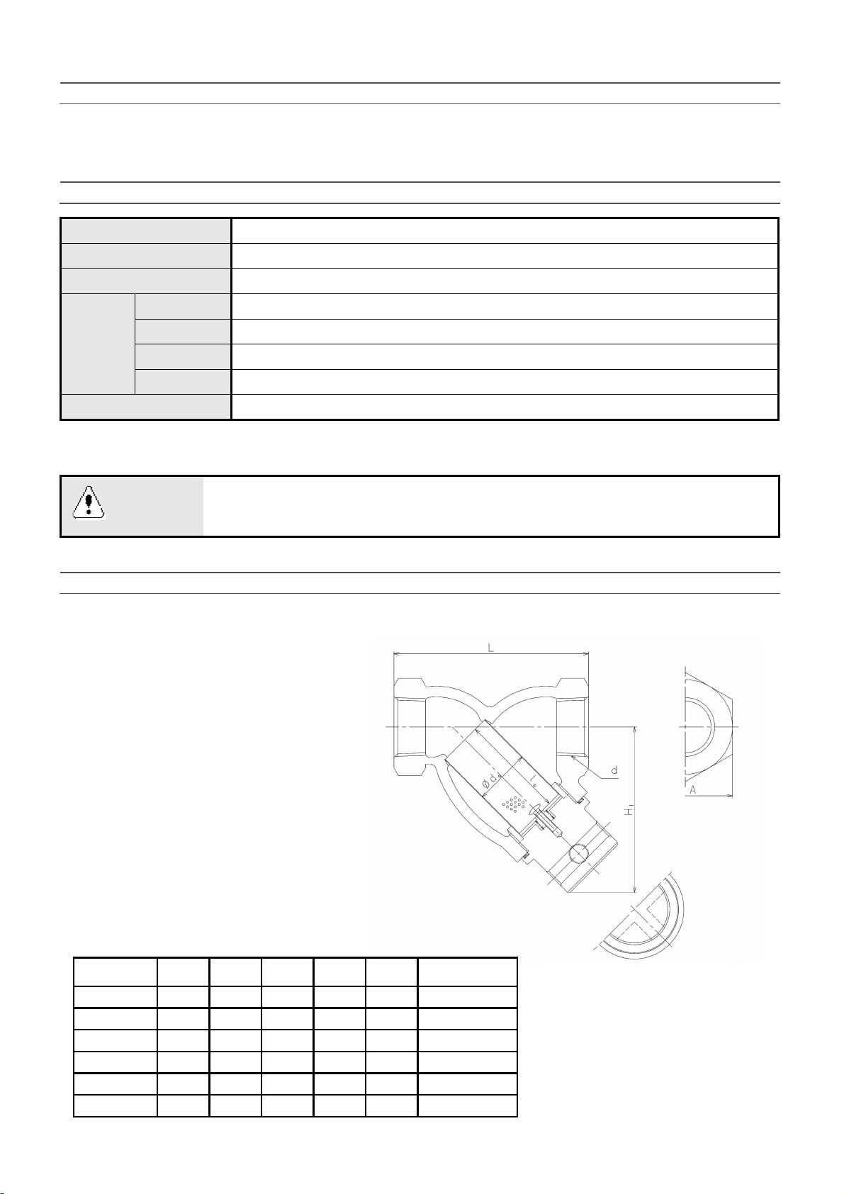
3. Dimensions and Weights············································· 1
4. Operation································································· 2
5. Nominal Size Selection ·············································· 2
5.1 Selection of nominal size······································· 2
5.2 Selection of nominal pipe size································· 2
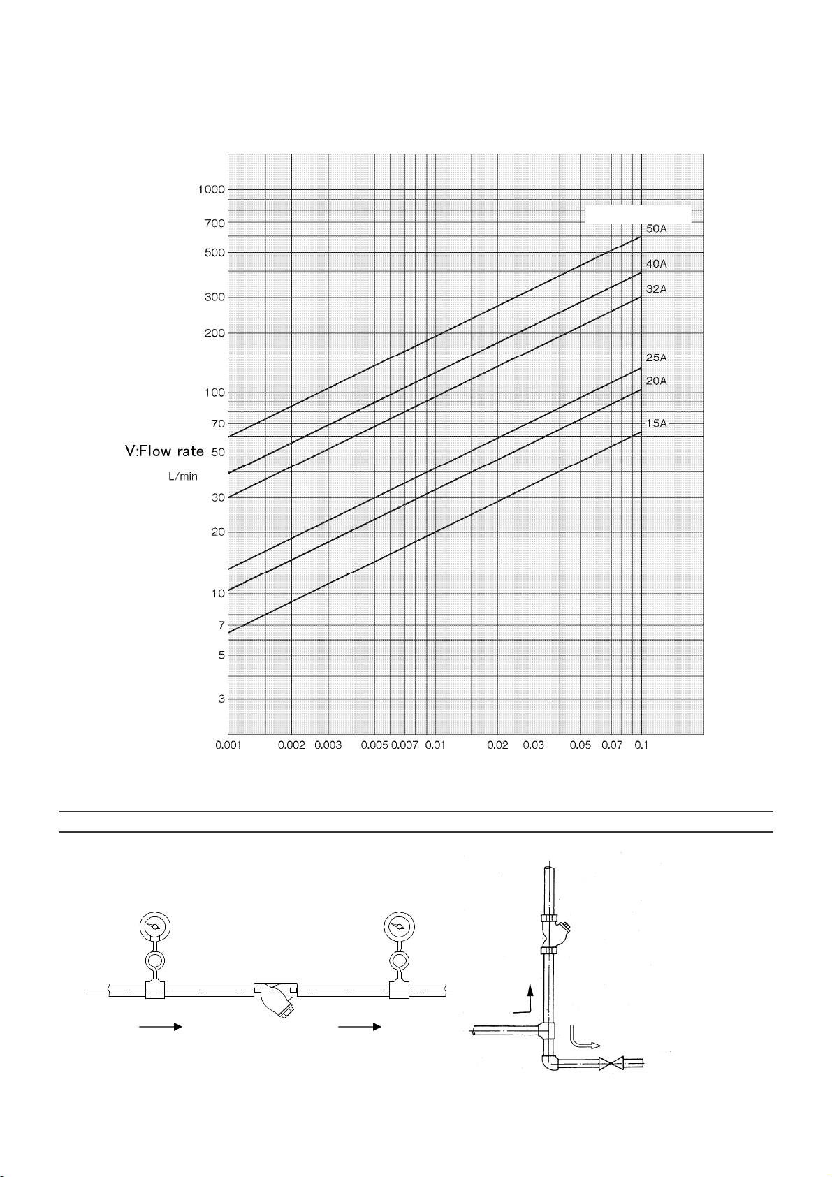
5.3 Nominal size selection chart··································· 3
6. Installation ······························································ 3
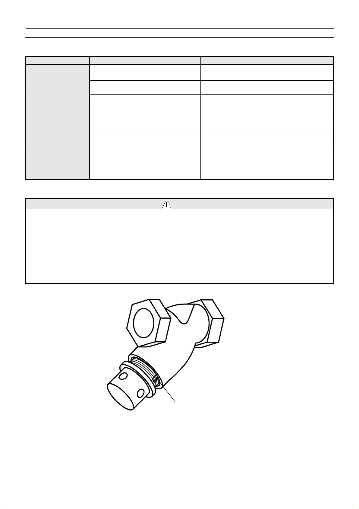
6.1 Piping example···················································· 3
6.2 Precautions during installation ································ 4
7. Operating Procedure ················································· 4
7.1 Precautions during operation·································· 4
8. Maintenance····························································· 5
8.1 Troubleshooting··················································· 5
8.2 Precautions during maintenance and inspection········· 5
8.3 Disassembly······················································· 6
8.4 Precautions during reassembly······························· 6
8.5 Reassembly························································ 6
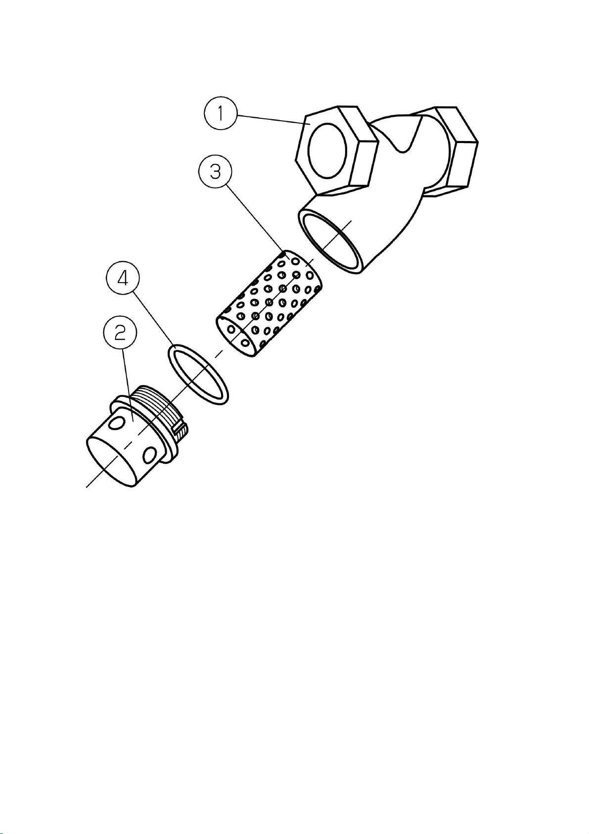
8.6 Exploded view····················································· 7
Warranty Information

1 ■EPDT-117b■
1. Features
The product is widely used for dust removal in various type of pipelines. Easy plug is installed on the cap
to secure the safety during maintenance.
2. Specifications
Application Air, Cold and hot water, Other non-dangerous fluids
Max. pressure 1.0 MPa
Max. temperature 80°C
Material
Body Ductile cast iron (FCD450)
Screen Stainless steel
O ring FKM
Cap C3604 (Brass)
Connection JIS Rc screwed
•Standard screen: φ2.5-7.21 holes/cm2perforations with 60 mesh filter
•The products with 20 to 100 mesh filter are also available upon request.
Caution
Please confirm that the indications on the product correspond with the specifications
of the ordered product model before use.
* Please consult factory in case they do not match each other.
3. Dimensions and Weights
(mm)
d L H
1
ds ls A Weight(kg)
Rc 1/2 75 70 20 35 21.8 0.7
Rc 3/4 90 84 25 50 26.8 0.9
Rc 1 110 96 32 60 30 1.7
Rc 1 1/4 135 114 40 70 36 2.8
Rc 1 1/2 145 120 45 75 41 4.0
Rc 2 170 131 56 90 46 5.1

2 ■EPDT-117b■
4. Operation
Dust, scale, and other foreign substances flowing into the product through the inlet port are removed by
the screen ③.
5. Nominal Size Selection
To make the best use of the product and to satisfy the operating requirements to the maximum,
take notice of the following.
5.1 Selection of nominal size
Select a nominal size of the product equivalent to that of the pipe (nominal pipe size = nominal size of
strainer). Note that use of a smaller nominal size increases the pressure loss through the strainer, and
may possibly reduce the equipment inlet pressure below the specified limit.
5.2 Selection of nominal pipe size
When selecting an appropriate nominal pipe size, it is necessary to consider fluid type, maximum flow
rate, permissible pressure loss, costs of piping and equipment, etc. If the nominal pipe size is smaller, the
costs of piping and equipment decreases while the pressure loss through the pipe increases to generate
disturbances, possibly resulting in pipe wear, noise and/or vibration. If the nominal pipe size is too large,
not only the costs of piping and equipment but also the thermal loss increases. As a reference, the
standard flow velocity is specified in the Japanese Industrial Standards (JIS) as a guide to select an
appropriate nominal pipe size. See the following table.
<<Standard flow velocity>>
Fluid Remarks Standard flow
velocity
Air Lower pressure 15 m/s [5-15]
Extremely low pressure: 0.1 MPa or less 10 m/s [3-10]
Water 2 m/s [2- 4]
* This table is based on the requirements provided in JIS F 7101 [Shipbuilding – Pipes
of machinery – Standard velocity of flow].
No.
Part Name
1 Body
2 Cap
3 Screen
4 O Ring
5 Cross recessed
head screws
6 Spacer
7 Spring

3 ■EPDT-117b■
5.3 Nominal size selection chart [Fluid: Water]
Screen: φ2.5-7.21 holes/cm2perforations with 60 mesh filter
6. Installation
6.1 Piping example
Fig. 1 Horizontal piping Fig. 2 Vertical piping
△
P:
Pressure Loss
MP
a
Nominal size
Blow

4 ■EPDT-117b■
6.2 Precautions during installation
Caution
1. When installing, check the direction of the product so that the fluid flowing and the arrow marked
on the product are in the same direction.
* Setting the product in wrong directions prevents the product from performing as intended.
2. When installing, enable the operator to pick up the screen from the product by reserving a working
space required, as shown in the table below, for maintenance and inspection (cleaning of the
screen).
* Failure to reserve a working space prevents maintenance and inspection (cleaning of the
screen).
3. Connect the product to the pipes securely.
* Improper connecting may cause fluid leakage from the pipes when vibration is applied to them,
resulting in scalds.
Maintenance
dimensions
Size H(mm)
15A 80
20A 100
25A 110
32A 130
40A 140
50A 160
7. Operating Procedure
7.1 Precautions during operation
Warning
Before letting the fluid into the product, make sure that there is no possibility of
danger when the fluid flows into the ends of piping.
* The hot fluid, if spouted out, may scald your skin.
* The fluid outflow may cause physical damage.
Caution
Use the product with a maximum pressure loss below 0.1 MPa. Periodically clean
the screen.
* Failure to follow this notice may damage the screen.
Clogging can be monitored when pressure gauges are installed both in upstream and downstream of the
strainer.

5 ■EPDT-117b■
8. Maintenance
8.1 Troubleshooting
Trouble Cause Remedy
Fluid does not flow.
1.
Screen
③
is clogged.
1.
Disassemble the product
and clean
the
screen ③.
2.
Stop valves in upstream and
downstream
are closed.
2.
Open the stop valves.
Excessive
pressure loss
1.
Screen
③
is clogged.
1.
Disassemble the product
and clean
the
screen ③.
2.
Pressure gauge is out
of order.
2.
Replace
the
pressure gauge with a
new one.
3.
Nominal size of the product is
too small for the piping
3.
Replace the product with a new one
proper for the piping nominal size.
Leakage from
the cap
1.
O ring is damaged.
1.
Replace New O
ring.
2.
Cap is loo
se.
2.
Tighten with the specified torqu
e
value
.
8.2 Precautions during maintenance and inspection
Warning
1. Completely discharge the pressure inside of the product and piping prior to disassembly and inspection.
When fluid is hot, cool down the product to the condition that it can be touched with bare hands.
* Failure to follow this notice may result in scalds or injury due to the residual pressure.
2. When the product is used for hot fluid, do not touch the product with bare hands.
* The product having hot fluid may scald your skin.
3. When removing the cap, fluid flows out after loosening the cap by 1 to 3 turns. When the product is
used for hot fluid, cool down the product to the condition that it can be touched with bare hands.
(Refer to the following [figure -3].)
* Hot fluid may scald your skin.
【
figure -3
】
Cut to release residual pressure

6 ■EPDT-117b■
8.3 Disassembly
Before disassembly, make sure that internal pressure has been completely released from the product
and the piping,
(1) Remove the cap ②. When the cap ②is strongly tightened, loosen it by applying a driver to a hole
on the side of the cap ②.
(Notice: Please check “8.2 Precautions during maintenance and inspection” prior to removing the
cap.)
(2)
Remove the screen ③from the body ①.
(3)
Clean the screen ③with compressed air or detergent.
8.4 Precautions during reassembly
Caution
1. When reassembling, connect all the parts securely.
* Failure to follow this notice may result in deformed or broken parts.
2. When reassembling, replace the O ring with a new one, and securely fasten the cap.
(Refer to the following list of O ring size.)
* Failure to follow this notice may result in fluid leakage, and may also scald your skin if the fluid is hot.
Nominal size
Size of O Ring
15A P26
20A P32
25A P40
32A G50
40A G55
50A G65
【O Ring Size】
8.5 Reassembly
Reassemble the product with the opposite procedures of disassembly (see 8.3 “Disassembly”).
Refer to the following torque value for tightening the cap②.
Nominal size
Specified torque
value(N・m)
15A 6
20A 6
25A 6
32A 10
40A 10
50A 20
【Specified torque value】

7 ■EPDT-117b■
8.6 Exploded view

2015.8
PDD-046e
Warranty Information
1. Limited warranty
This product has been manufactured using highly-advanced techniques and subjected to
strict quality control. Please be sure to use the product in accordance with instructions on
the manual and the label attached to it.
Yoshitake warrants the product to be free from any defects in material and workmanship
under normal usage for a period of one year from the date of receipt by the original user, but
no longer than 24 months from the date of shipment from Yoshitake’s factory.
2. Parts supply after product discontinuation
This product may be subject to discontinuation or change for improvement without any prior
notice. After the discontinuation of the product, Yoshitake supplies the repair parts for 5
years otherwise individually agreed.
3. This warranty does not cover the damage due to any of below:
(1) Valve seat leakage or malfunction caused by foreign substances inside piping.
(2) Improper handling or misuse.
(3) Improper supply conditions such as abnormal water pressure/quality.
(4) Water scale or freezing.
(5) Trouble with power/air supply.
(6) Any alteration made by other than Yoshitake.
(7) Use under severe conditions deviating from the design specifications
(
e.g. in case of corrosion due to outdoor use).
(8) Fire, flood, earthquake, thunder and other natural disasters.
(9) Consumable parts such as O-ring, gasket, diaphragm and etc.
Yoshitake is not liable for any damage or loss caused by malfunction or defect of the product.
INTERNATIONAL DEPT.
955-5, Miyamae, Irukadeshinden, Komaki, Aichi, 485-0084, Japan
Phone: +81-568-75-4432 Fax: +81-568-75-4763
E-mail: Intntl@yoshitake.co.jp
Table of contents
Other Yoshitake Plumbing Product manuals
Popular Plumbing Product manuals by other brands

oventrop
oventrop Regudis W-HTE operating instructions

IB RUBINETTI
IB RUBINETTI REFLEX 200 Fitting instructions

Vallone
Vallone COMO 03 installation instructions

Symmons
Symmons Dia SLS-3512 Series Installation Brief

Omnires
Omnires Y1236/KROCR Installation and Maintenance

Hans Grohe
Hans Grohe Focus N 71140 1 Series Installation/User Instructions/Warranty