Yoshitake SY-40 Series User manual

MODEL SY-40 Series
STRAINER
PRODUCT MANUAL .
Thank you very much for choosing the Yoshitake’s product. To ensure the correct and safe use
of the product, please read this manual before use. This manual shall be kept with care for
future references.
The symbols used in this manual have the following meanings.
Warning This symbol indicates a potentially hazardous situation that, if not
avoided, could result in death or serious injury.
Caution This symbol indicates a hazardous situation that, if not avoided, may
result in minor or moderate injury or may result in only property
damage.
Table of Contents
Usage of the product·····················································1
1. Features ····································································1
2. Specifications····························································1
3. Dimensions and weights ···········································2
4. Operating mechanism ···············································3
5. Selection of nominal size
5.1 Selection of nominal size····································4
5.2 Selection of piping nominal size·························4
5.3 Nominal size selection chart·······························5
6. Installation procedure
6.1 Example of piping···············································6
6.2 Caution in installing the product ······················6-7
7. Operation procedure
7.1 Caution in operating the product ························7
8. Maintenance procedure
8.1 Troubleshooting··················································7
8.2 Caution in maintenance and inspection··············8
8.3 Disassembly procedure······································8
8.4 Caution in assembling after disassembly···········8
8.5 Assembly procedure···········································8
9. Exploded view ···························································9
Information on after-sales services
■EPDT-167b■

Usage of the product
The product is widely used for dust removal from various types of pipelines. Especially, a strainer shall
be installed upstream of a pressure reducing, temperature regulating, solenoid or trap valve to protect
and maintain it.
1. Features
(1) The product is a high-flow marine type with as large a filtration area as possible to avoid clogging and
consequent problems such as flow rate drop.
(2) Ones with a nominal size of 65A or above have been downsized to the possible minimum sizes and
thus ease the piping.
(3) SY-40C/40C-N is highly resistant to corrosion as it has the internal and external body surfaces coated
with nylon 11 or nylon 12.
(4) For the standard screens, 80 mesh ones are used for SY-40/40H and 60 mesh ones for
SY-40C/40C-N according to the common specifications for machinery and equipment installation
work.
2. Specifications
Model SY-40 SY-40C SY-40C-N SY-40H
Nominal size 15-300A15-150A
Application Steam, air, hot or cold
water, Oil and other
non-dangerous fluids
Air, hot or cold water and other
non-dangerous fluids
Steam, air, hot or cold
water and other
non-dangerous fluids
Maximum pressure 1.0MPa 2.0MPa
Maximum temperature 220℃60℃220℃
Material Body Ductile cast iron
Screen Stainless steel
Connection JIS 10K FF flanged JIS 20K FF
flanged
Standard
screen Perforations φ2.5-7.21 holes/cm2
Mesh 80 mesh 60 mesh 80 mesh
・SY-40C has the external and internal body surfaces coated with nylon 11 (15A to 200A) or nylon 12
(250A and 300A).
・SY-40C-N has the external and internal body surfaces coated with nylon 12 (15A to 150A).
・Ones with 20 to 100 mesh filter are also available upon request.
・Ones with single layer of perforations are also available upon request.
Nominal size 15 to 80A…φ1.3-16.2 holes/cm2
100A or above…φ1.5-11.2 holes/cm2
・Ones with brass plug may also be manufactured.(except for SY-40C-N)
・Rust-proof (hot dip galvanized) ones are also available with nominal sizes of 65A or above.(except
for SY-40C/40C-N)
- 1 - ■EPDT-167b■

3. Dimensions and weights
[Figure 1] 15-50A [Figure 2] 65-300A
(No plug is provided with 15 to 32A ones.)
■SY-40,40C, 40C-N (mm)
Nominal
size LH1ds Ls Connection Weight (kg)
15A 130 61 22 40 --- 1.9
20A 140 75 27 56 --- 2.5
25A 160 88 34 66 --- 4.0
32A 175 104 43 76 --- 5.2
40A 190 115 50 85 R1/2 6.7
50A 225 140 61 107 R 1/2 10.2
65A 255 167 73 125 R 1/2 14.5
80A 330 190 88 130 R 1/2 18.3
100A 370 225 108 180 R 3/4 29.7
125A 415 263 136 200 R 3/4 40.5
150A 495 315 160 250 R 3/4 66.0
200A 565 385 210 300 R 3/4 95.8
250A 690 460 260 370 R 3/4 167.5
300A 840 556 315 442 R 3/4 286.0
■SY-40H (mm)
Nominal
size LH1ds Ls Connection Weight (kg)
15A 130 61 22 40 --- 1.9
20A 140 75 27 56 --- 2.5
25A 160 88 34 66 --- 4.0
32A 175 104 43 76 --- 5.2
40A 190 115 50 85 R 1/2 6.7
50A 233 140 61 107 R 1/2 10.2
65A 290 167 73 125 R 1/2 15
80A 316 190 88 130 R 1/2 19
100A 360 225 108 180 R 3/4 28
125A 415 263 136 200 R 3/4 42
150A 495 315 160 250 R 3/4 68
- 2 - ■EPDT-167b■

4. Operating mechanism
Part name
№
1 Body
2 Screen
3 Gasket
4 Cap
[Figure 3] 15-50A5 Cover
(No plug is provided with 15 to 32A ones) 6 Plug
7 Strainer retainer
8 Hexagon nut
9 Stud bolt
10 Washer
[Figure4] 65-300A
(No strainer retainer is provided with 65 to 80A ones.)
Dust, scale and other foreign matter from the fluid flowing into the strainer through the
inlet port are removed by the screen (2).
- 3 - ■EPDT-167b■

5. Selection of nominal size
To make the best use of the strainer and satisfy the operating requirements to the maximum,
take notice of the following.
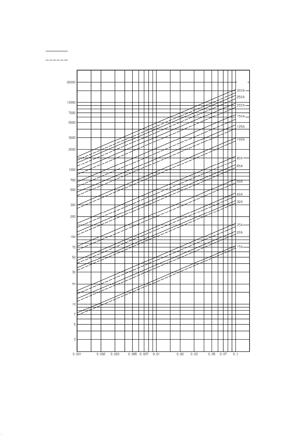
The preferred initial pressure loss is 0.02-0.03 MPa.
5.1 Selection of nominal size
Select a nominal size equivalent to that of the pipe (piping nominal size = nominal
size of strainer). Note that the use of a smaller nominal size increases the pressure loss
through the strainer, possibly reducing the machine inlet pressure below the specified limit.
5.2 Selection of piping nominal size
When selecting the piping nominal size, it is necessary to consider the fluid type, maximum
flow rate, permissible pressure loss, piping and equipment cost, etc. With a smaller piping nominal
size, the piping and equipment cost decreases but the pressure loss through the pipe increases to
generate disturbances, possibly resulting in pipe wear, noise and/or vibration. With too large a piping
nominal size, however, not only the piping and equipment cost but also the thermal loss increase. The
standard fluid velocity has been specified in the Japanese Industrial Standards (JIS) as a guide to
select an appropriate piping nominal size.
<<Standard fluid velocity>>
Fluid Remarks
Standard
flow velocity
Saturated steam
Auxiliary piping for vacuum or small-diameter
piping 15 m/s
(10-20)
Large-diameter piping 30 m/s
(20-40)
Superheated steam Piping diameter: approx. φ75 – φ250 40 m/s
(30-50)
Piping of high-grade material 70 m/s
(65-80)
Inlet of steam coil 0.3-0.7MPa 30 m/s
(25-30)
Air
Higher pressure: 1.0 MPa or more 20 m/s
(20-25)
Lower pressure 15 m/s
( 5-15)
Extremely low pressure: 0.1 MPa or less 10 m/s
( 3-10)
Water or oil 2 m/s
( 2- 4)
* This table shows a standard flow velocity of each type of fluid set based on the
requirements defined in JIS F 7101 (Shipbuilding – Pipes of machinery –
Standard velocity of flow).
- 4 - ■EPDT-167b■

5.3 Nominal size selection chart (Fluid: Water)
- 5 - ■EPDT-167b■
Screen:φ1.3-16.2 holes/cm2(φ1.5-11.2 holes/cm2) perforations without mesh filter
Screen:φ2.5-7.21 holes/cm2perforations with 80 mesh filter
ND
V: Flow rate
(
L/min
)
ΔP: Pressure loss(MPa)

6. Installation procedure
6.1 Example of piping
[Figure 5] Horizontal piping [Figure 6] Vertical piping
(1) The amount of clogging matter may be estimated from the differential pressure measured with
pressure gauges installed upstream and downstream of the strainer. (See Figure 5.)
(2) They shall be installed with the cap (4) or cover (5) facing downward. If drainage or similar
problem may occur in a steam line, the cap (4) or cover (5) shall be installed so that the cap or
cover faces sideways.
(3) If the product can only be piped to run the fluid from the bottom to the top, a blow valve shall be
installed to remove the scale accumulated at the bottom of the riser pipe. (See Figure 6.)
6.2 Caution in installing the product
Warning
(1) The product is heavy and shall be securely suspended with a hoist or the like when
installed. For the weight of the product, see section 3 “Dimensions and weights.”
* Failure to suspend the product may cause it to fall down, possibly resulting in injury.
Caution
(1) When installing, install the pipe so that the fluid flowing direction follows arrow on the body.
* Connecting pipes in wrong directions prevents the product from performing as intended.
(2) Firmly support pipes and secure the product.
* If an excessive stress is applied to the pipes, the product may be deformed.
(3) When installing the product, reserve a space required for maintenance and inspection
(cleaning of the screen) as specified in Figure 7.
* Failure to do so prevents later maintenance and inspection (cleaning of the screen).
(4) Firmly connect pipes.
* If incompletely connected, the fluid may leak from pipes when vibration is applied. The
fluid may scald your skin.
(5) If no foreign matter is allowed to pass through the product, please contact us.
* The foreign matter corresponding to the specified mesh size may not be completely
caught constitutionally.
Blow
- 6 - ■EPDT-167b■

(mm)
Nominal
size
H
15A 80
20A 105
25A 125
32A 145
40A 160
50A 200
65A 220
80A 245
100A 310
125A 365
150A 445
200A 550
250A 675
300A 805
[Figure 7] Space for removing the screen
7. Operation procedure
7.1 Caution in operating the product
Warning
(1) Before letting the fluid into the product, check that there will be no possibility of danger if
fluid flows into the ends of piping.
* The hot fluid, if spouted out, may scald your skin.
* The fluid outflow may cause physical damage.
(2) After aerating, do not retighten the cap or cover gasket.
* Doing so may break the gasket, possibly resulting in external leak.
Caution
(1) Use the product with the maximum pressure loss below 0.1MPa. Periodically clean the
screen.
* The screen may be broken.
(1) The amount of screen clogging matter can be monitored with pressure gauges installed
upstream and downstream of the strainer.
8. Maintenance procedure
8.1 Troubleshooting
Problem Cause Solution
Fluid does not flow. 1. Screen (2) is clogged.
2. Upstream and downstream of
stop valves are closed.
1. Overhaul and clean screen (2).
2. Open the stop valves.
Excessive pressure
loss
1. Screen (2) is clogged.
2. Pressure gauge is out of order.
3. Nominal size is much
smaller than specified.
1. Overhaul and clean screen (2).
2. Replace pressure gauge with a
new one.
3. Change to adequate nominal size.
- 7 - ■EPDT-167b■

8.2 Caution in maintenance and inspection
Warning
(1) When overhauling or inspecting the product, check that the product and piping internal
pressures have been released to the atmosphere.
When the fluid is hot, cool it down until it can be touched by bare hand.
*The residual pressure in the product or piping may lead to injury or burn.
(2) When using a hot fluid, do not touch the product by bare hand.
*Doing so may scald your skin.
(3) Clean the screen periodically.
*Scale clogging to the screen may cause its damage.
8.3 Disassembly procedure
(1) After checking that no pressure remains in the strainer, remove the cap (4) and gasket (3) for 50A
or smaller ones or the hexagon nut (8), cover (5) and gasket (3) in this order for 65A or larger
ones.
(2) Remove the screen (2) from the body (1) and clean it. For 100A or larger ones, the screen (2) is
equipped with a strainer retainer (7). The strainer retainer (7) has usually been hung on the body
(1) and the screen (2) shall be removed by rotating to the point where the notch on the body (1)
is aligned with the strainer retainer (7). (See Figure 8.)
8.4 Caution in assembling after disassembly
Caution
(1) When assembling, completely assemble all parts.
*The parts may be deformed or broken.
(2) When assembling, replace the gasket with a new one and uniformly tighten bolts in the
diagonally opposite directions to prevent uneven tightening.
*The fluid may leak out. If hot, it may scald your skin.
8.5 Assembly procedure
(1) Clean the gasket mating faces of the body (1) and cap (4) or cover (5) and install the cleaned
screen (2) to the body (1). For 100A or larger ones, the screen (2) shall be installed with the
strainer retainer (7) aligned with the notch on the body (1) and rotated until the strainer retainer
(7) is hung on the body (1). (See Figure 8.)
(2) Install a new gasket (3) and install the cap (4) or cover (5).
Notch
(1) Body
(2) Screen
(7) Strainer retainer
[Figure 8]
- 8 - ■EPDT-167b■

9. Exploded view
- 9 - ■EPDT-167b■
【図9】15-50A
[Figure 10] 65 to 300A
is provided as consumable parts.
(3) Gasket
[Figure 9] 15 to 50A
(1) Body
(
2
)
Screen
(3) Gasket
(4) Cap
(6) Plug
Not provided with 15 to
32A ones.
(5) Cover
(6) Plug
(7) Strainer retainer
Not provided with 65 to 80Aones.
(9) Stud bolt
(2) Screen
(10) Washer(SY-40C/40C-N)
(8) Hexagon nut
(1) Body
This manual suits for next models
4
Table of contents
Other Yoshitake Plumbing Product manuals
Popular Plumbing Product manuals by other brands

BEMIS
BEMIS BioBidet PEARL HSB-100 user manual

Dometic
Dometic SANIPOTTIE owner's manual

Wellis
Wellis Igneus installation manual

DXV
DXV Lyndon D35109400 installation instructions

Luxier
Luxier KTS21-TB installation instructions

Hans Grohe
Hans Grohe Talis Care 32035000 Instructions for use/assembly instructions