YouKits MT1 QRP User manual

Youkits MT1 QRP Long Wire Antenna Tuner
MT1 is designed for the high-impedance long wire antenna, which can be used in the range of
10m to 40m, with the power handling of about 10W ( power handling peak is about 20W),
consisting of two parts, namely LC matching circuit and the VSWR power detection circuit .

No.
Amount
Specification
PCB
1
A YKT-02 circuit board
R1
1
3.3K carbon film resistor
R2
1
200 Ωcarbon film resistor
R3、R4
2
4.7K carbon film resistor
D1、D2
2
1N60 diode
C1
1
30P tunable capacitor
C2
1
100P monolithic capacitor
C3、C4
2
104 ceramic capacitor
C5
1
223P dual capacitor
S1
1
2*2 toggle switch
S2
1
1*12 band switch
Meter
1
500uA meter
T1 magnet ring
1
FT37-43 magnet ring (black)
L1 magnet ring
1
T68-2 magnet ring (red)
Antenna pedestal
1
BNC antenna pedestal
Binding post
2
A black one and a red one each
Knob
2
A-01(two)
28# enamel insulated
wire
2
A red one and a yellow one
24# enamel insulated
wire
1
A red one
2.5*3 screw
2
Used for fixing C5
3*5 screw
4
Used for fixing PCB
Chassis
1
A Chassis
Parts List

Production
Production of T1
Cut the yellow and the red 28 # enamel insulated wire each for about 20cm long, which are
winded on FT37-43 magnet ring for ten loops after being twisted together.
Twist both end of the red and the yellow wire together as an intermediate tap.
Production of L1
Cut the red 24 #enameled insulated wire about 1m long, and wind on T68-2 magnet ring,
then tap for every three loops, totaled12 taps, with 10 tapped ones and the top the end leads.
Each tap is about 5mm long and is twisted tightly. Soldering iron is used to solder each tap and lead.
The enameled insulated wire provided in the kit can be soldered, which can be soldered after using
soldering iron ironing the coat of the wire for a while.

The 1-12 feet of band switch S2 should be bended outward, in that case magnet ring L1 can be put
within .Solder foot A with the 30mm 24 # enameled insulated wire.
Put the winded magnet ring L1 on the S2, and connect the top and the end part of the winded
wire on foot 1and foot 2 of S2 respectively, then connect other 10 taps with 2-11 feet.
Weld PCB
Installing and wielding R1-R4

Installing and welding D1-D2。
Installing and welding C1-C4。
Installing and welding
The intermediate tap of T1 should be welded in the bonding pad next to R1
Cut the 24 # enameled insulated wire for about 30mm long, with one end through T1 and welded
on the pad under C1. Install and weld S1 on the other side of the PCB.

Install the chassis
。
Install the BNC seat and two binding posts in the corresponding position on the cabinet..
Fix the header and PCB with screws.

The other end of wire passing through T1 is installed on the pedestal BNC, and pedestal BNC’s
ground wielding piece is soldered on the ground wielding piece of PCB. The positive and negative terminals of the
meter are connected to the + and – of PCB respectively.
Install S2(L1)and C5 on the chassis.
Connect PCB’s OUT pad with the S2's 12 foot by using the 24 # enameled wire, and weld GND
pad of PCB on the middle foot pad and black terminal of C5 with 24 # enameled insulated wire.
Two feet of C5 are welded together and welded to the red terminal.

The band switch S2 counterclockwise in the end, making the mark target exactly to A. Switch dual
capacitor C5 counterclockwise in the end, making the mark target to 0, tighten the knob, and the installation is over.
More attentions should be spent on these following points:
1. Inductor finishing end of L1 must be welded to the 1 and 2 feet of band switch S2 . and pad
2. OUT on the PCB must be soldered to 12 foot of S2.
3. Two fine-tuning capacitor of duel capacitor C5 must be tuned to the position of minimum capacity
4. as the above picture shows. C5of the kit has been tuned to the position of minimum capacity, so no
5. need to be turned. The extended long axis kit of C5 has been installed, which needs no more spin.
6. If there is a deviation after the completion of the final assembly of the knob, the adjustment is allowed.
7. Some of the kit components are plastic parts, such as the band switch S2, Do not use excessive f
8. orce when install them, in order to avoid damage to the device.

Adjustment:
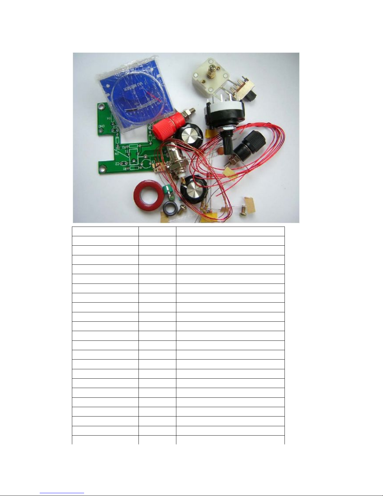
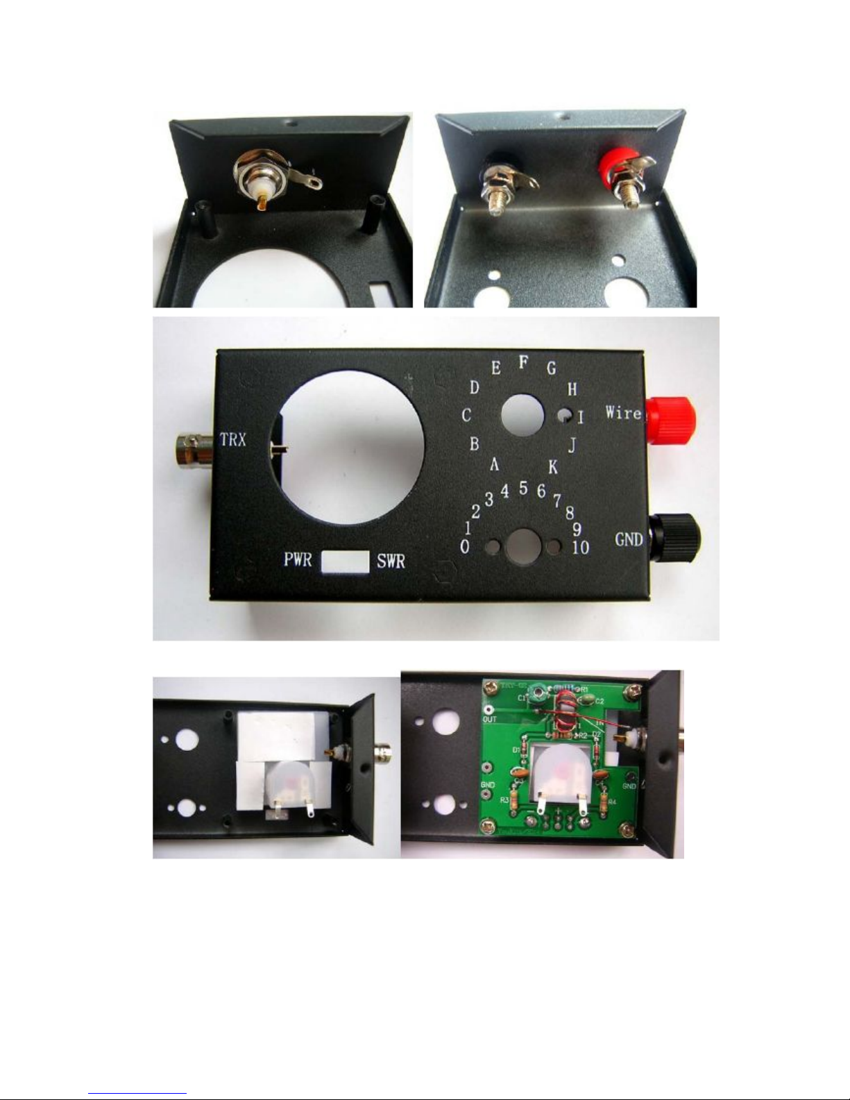
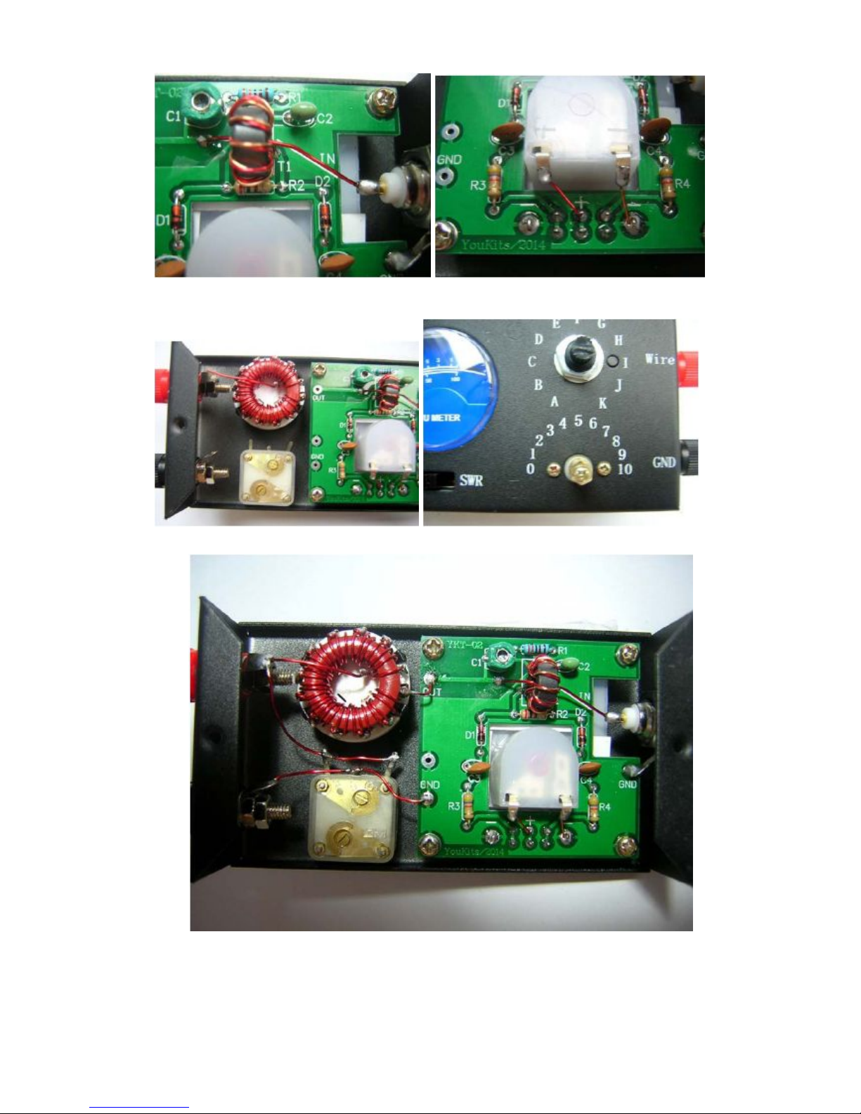
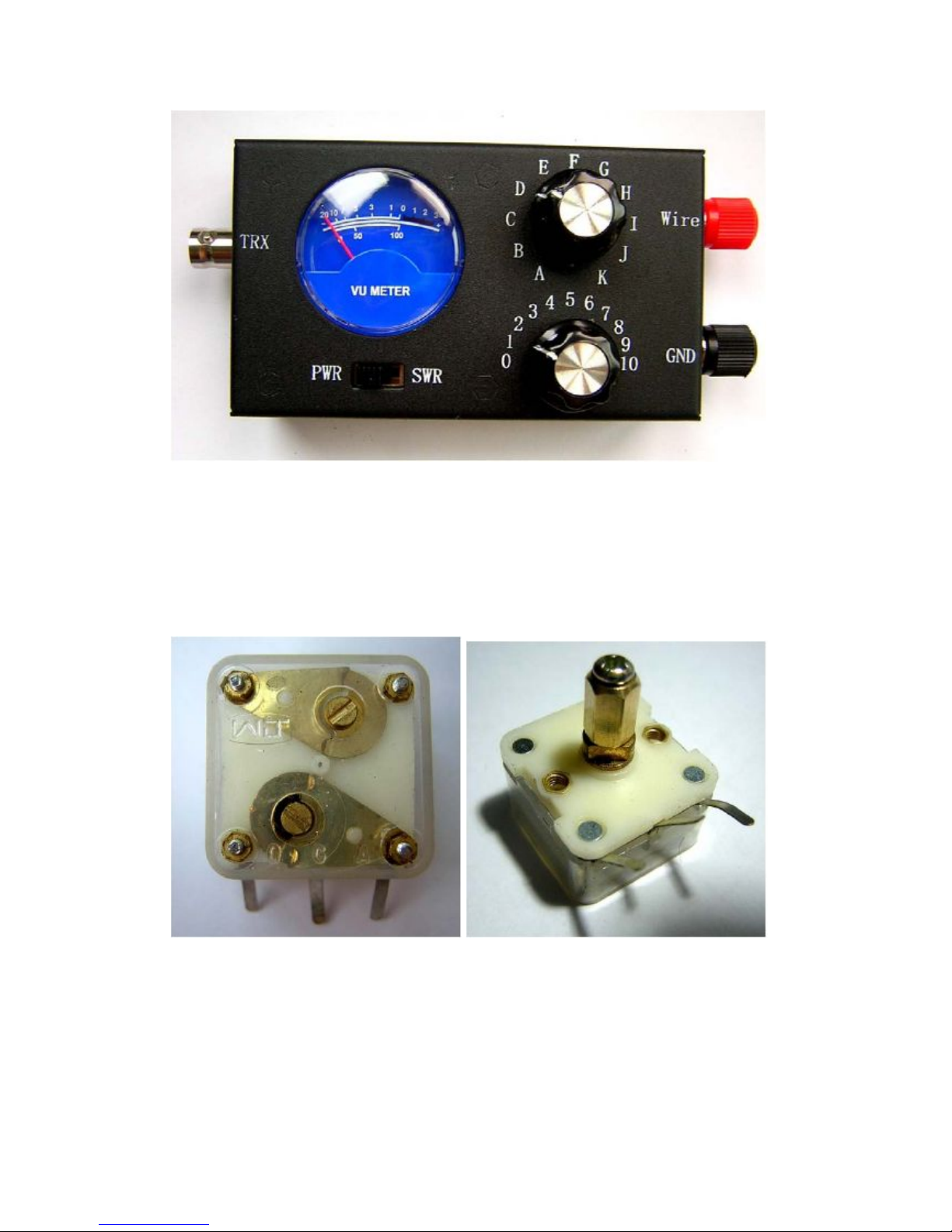
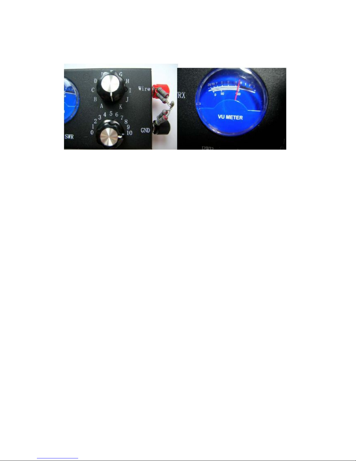
The band switch S2 clockwise in the end (see the neutral place of above Figure, when L1 is through),
duel capacitor C5 also clockwise in the end (in this case C5 is in the smallest capacity). Connect a 50 ohm,
no less than 5 watts of power dummy load in the Wire and GND terminals, and tuneback S1 to SWR position.
ConnectTRX end with radio, which is tuned in mode CW, with probably about 5 watts of transmit power
and radio frequency at 20m band (or 15m, 40m band can be ok), so that the radio sends a continuous
CW signal. Adjusting the adjustable capacitor C1, making the SWR meter shows zero or minimal degree,
tuning back S1 to PWR position. At this time, meter can be adjusted between 0dB to -1dB.
Usage:
Length selection of the long antenna: to get good results, longer antenna should be chosen. But
the equipment temporarily erected in the wild should be shorter in the case of convenience, with the
consideration of the length of the antenna which should not be close to the half wavelength and the
integer multiple of the half wavelength of the used frequencies. An eight-meter antenna is chosen for
7 MHz and all shortwave bands above7 MHz amateur brands. If it is used for over 14 MHz , brands,
the antenna should be about 3-4 meters long.
GND: At least one GND should be used at the length of a quarter of the minimum operating wavelength.
If it is possible, each brand should at least have one GND at the length of a quarter of the wavelength of
the ground. It is ok to put the GND on the floor.
Adjustment: After connecting the radio, antenna tuner, and antenna, one can adjust the long wire antenna
tuner to tune. Firstly, the work and tuning switch of long wire antenna tuner SW5 should be dialed to the
tuning position, and radio tuned to work brand by pressing telegraph key or press the PTT in FM mode,
making the output power of about 3-5 watts. S1 switch is tuned to the SWR position, and the position of
C5 is adjusted to find the minimum point of the VSWR by changing the position of S2
Withdrawal and Amendment

Antenna is about 8 meters.
GND us about 4.8 or 9.6 meters long.
YouKits
Table of contents