yourDroid D2-6 User manual

D2-6 kit instructions
Introduce:
D2-6 type bluetooth car kit is the latest version of D2 series kit, single-chip microcomputer
as the core, through program control achieves tracking, obstacle avoidance, Bluetooth mobile
phone control, gravity induction control functions.
The car with the serial interface, through the connecting the Bluetooth module to achieve
wireless remote control function.
Compared to the previous D2 series car can only control forward, D2-6 added more features,
not only can achieve forward, but also can be achieve fall back.
Lithium batteries, rechargeable, reduce the cost of use. (You need to prepare your own
battery, this kit has no battery)
Feature:
Operating voltage: DC 3.7V (one lithium battery)
Circuit board size: 105mm * 72mm
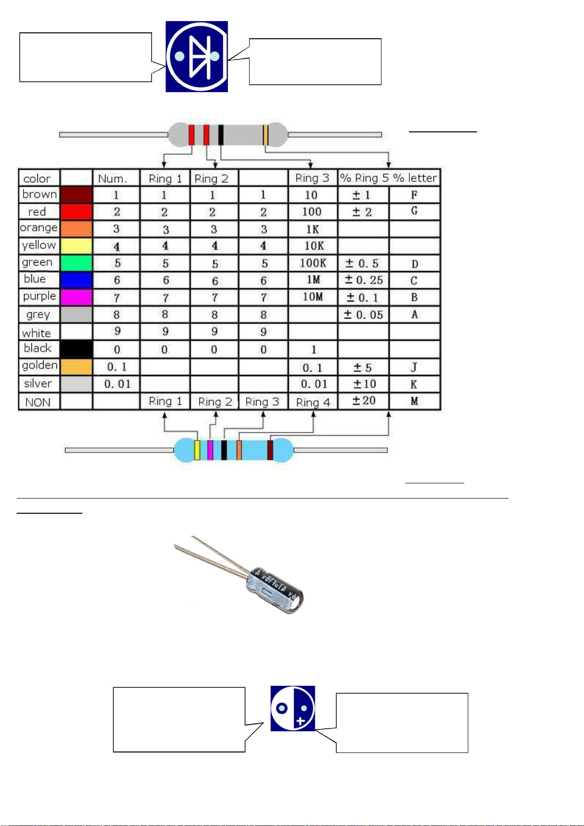
Various light-emitting diodes
3MM infrared emitting diodes. Part of the lamp beads transparent, long legs positive, short
legs negative
3MM infrared receiver diode, lamp beads part is black, long legs positive, short legs
negative.
3MM green light-emitting diodes, lamp beads part is green, green light. Long legs positive,
short legs negative.
5MM red light-emitting diodes, light beads part is red, red light. Long legs positive, short
legs negative.

The above diodes in the car PCB installation location has the following symbols.
Here is the cathode,
connect the long leg
of the diode
Here is the negative,
connect the short leg
diode
Color ring resistance
22 ohms 5%
470KΩ1%
If you are not sure the resistance, you can use a multimeter to measure before the
installation.
Electrolytic capacitor
Electrolytic capacitor, long legs for the cathode, short leg for the negative
Electrolytic capacitors in the car mounted on the PCB location of the following symbols
Here is the cathode,
connect the
electrolytic capacitor
long legs
Here is the negative,
then the electrolytic
capacitor short legs

SMD Integrated Circuit
Learn to identify the first foot patch of IC
Note that there
is a small
concave point
The bottom of the
small point is
the first foot
On the PCB, this pad
connects to the first pin
of the LM339
SMD integrated circuit L9110S
Note that there
is a small
concave point
The bottom of the
small point is
the first foot

On the PCB, this pad
connects to the first
pin of the L9110S
Single - chip microcomputer STC15W201S
Single-chip is inserted on the IC Block, the assembly IC base, we should pay attention to the IC Block has
a semi-circular small gap
This mounting gap should be aligned with the semicircular notch on the top of the PCB. Single-chip IC
insert into the seat, we must pay attention to the semi-circular chip on the gap should also be semi-
circular gap with the IC on the same direction.
After the completion of the installation of all the pictures for reference only

Note that there is a
root fly wire connected
with the resistance of
the shear pin
Backside of the picture

www.banggood.com
Two pairs of infrared diodes for tracking, the top and the caster vertex distance is about 5MM
2B: put a three-way sleeve into the axle

www.banggood.com
2C: Insert a washer into the steel shaft next to the 3-way sleeve


if the gap is
too small will
cause the
wheel is not
The center hole and the
axle of the three-way
sleeve should be
parallel to each other,
otherwise the wheel


Solder the motor power cord
The following is the debug section
Infrared sensitivity adjustment

Four adjustable
resistors are used for
IR receiver sensitivity
adjustment
Four light-emitting diodes are used for
infrared reception sensitivity
indication.
Adjusts the sensitivity of the two infrared rays used for tracking
Remove the microcontroller
Car flat, first, a pair of infrared tube on the black track alignment, the figure is the D7 and D3 aligned black
track

Counterclockwise adjust the adjustable resistor R10 until the light-emitting diode D14 light,
and then clockwise adjust the adjustable resistance R10, until the light-emitting diode D14
completely extinguished, it adjusted. Move this set of infrared rays between the black track
and the white area. It can be seen that when the black track is aligned, the light emitting
diode D14 is turned off, and when the white area is aligned, the light-emitting diode D14 is
turned on.
The remaining set of infrared pairs of traces, D5 and D9, is adjusted as described above,
using the adjustable resistor R16, and the light-emitting diode D12 indicates the sensitivity.
Note: Due to the use of infrared, the car is not suitable for outdoor use, outdoor sunlight in
the infrared can also be received, causing interference.
The sensitivity of the two sets of infrared rays used for obstacle avoidance is
adjusted
flat car, erected a white paper in front, about 5CM or so
One set of infrared pairs of tubes D4 and D8, for example, another group of the D6 and D10
regulation of the same method, D4 and D8 adjustment using adjustable resistor R13, LED D13
used to indicate its sensitivity. Another set of regulators for the D6 and D10 use adjustable
resistor R19, light-emitting diode D11 used to indicate its sensitivity.
First adjust clockwise R13, until the light-emitting diode D13 off, and then counter-
clockwise adjustment R13, when the light-emitting diode D13 lit, stop the adjustment, so that
the sensitivity is adjusted well.
Note: Obstacle avoidance function is only suitable for white and good reflective obstruction
objects, and can not be used outdoors, outdoor sunlight in the infrared can also be received,
causing interference.
Popular Toy manuals by other brands

Hasbro
Hasbro Brother Bear 34901 instructions

Fisher-Price
Fisher-Price Little People 74888 instructions

Staufenbiel
Staufenbiel EPSILON COMPETITION V3 instruction manual

Fisher-Price
Fisher-Price GEOTRAX T7160 user manual

Hasbro
Hasbro G.I. Joe Desert Striker instructions

Horizon Hobby
Horizon Hobby miss elam owner's manual