YSD OT2115 Quick start guide

1
Manual of product installation and use
Datong Autosun
Power Control
Co.,LTD
Model OT2115
Engine electronic governor
Speed drive

2
目 录
SAFETY PRECAUTIONS..................................................................................... 1
1.OVERVIEW.....................................................................................................2
2. WORKING PRINCIPLE................................................................................. 4
2.1 DRIVER............................................................................................4
2.2 ACTUATOR.........................................................................................6
2.3 ANGULAR POSITION SENSOR................................................................ 6
3.MAIN TECHNICAL INDEX............................................................................. 6
3.1 DRIVER............................................................................................6
3.2 ACTUATOR.........................................................................................7
4、INSTALL.....................................................................................................7
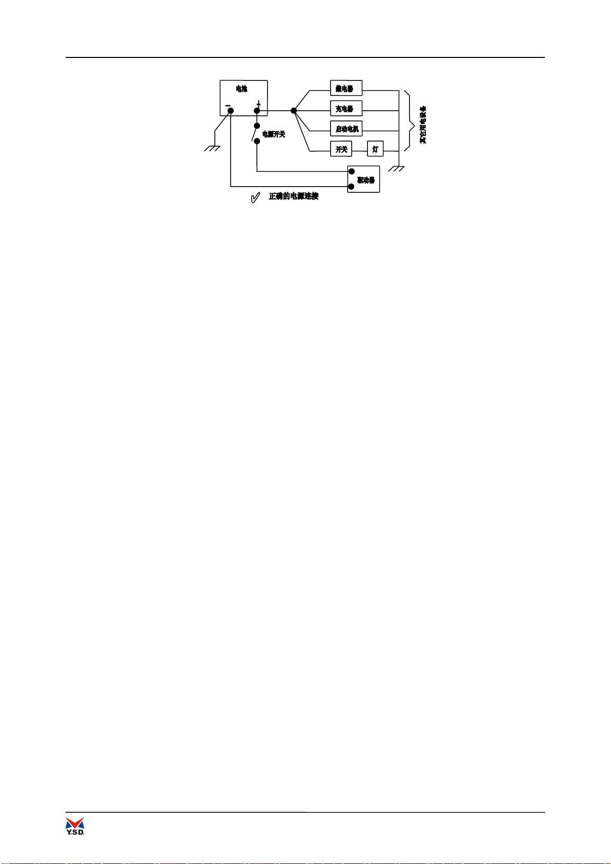
4.1 POWER............................................................................................. 7
4.2 DRIVE INSTALLATION.........................................................................8
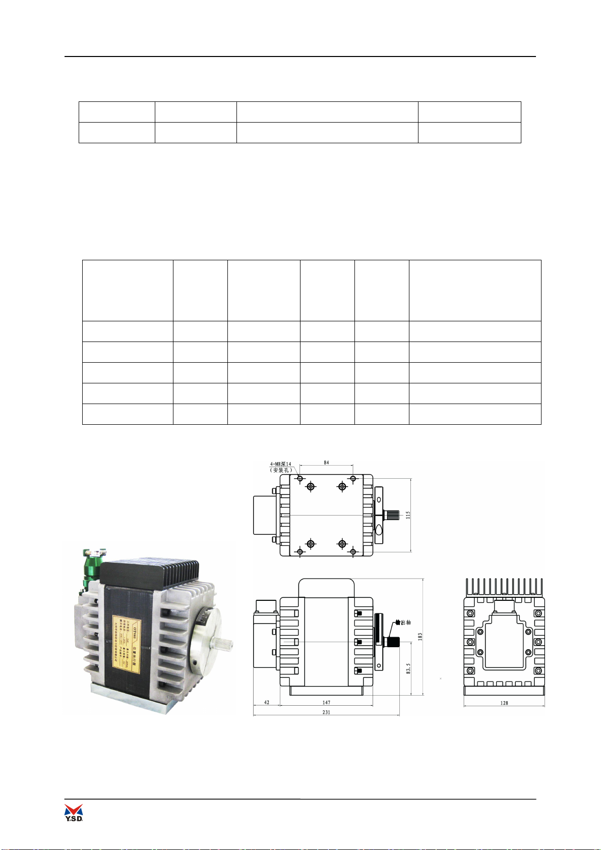
4.3 ACTUATOR INSTALLATION....................................................................8
4.4 ACTUATOR MOUNTING BRACKET............................................................. 9
4.5 LINKAGE DEVICE.............................................................................10
4.6 ELECTRICAL CONNECTION.................................................................. 11
4.7 SHIELDING WIRE.............................................................................12
4.8 ADJUSTMENT....................................................................................13
5、COMMON TROUBLESHOOTING GUIDE..........................................................13

1
Safety Precautions
Warning - Read the Instructions
Before installation, operation, commissioning or maintenance for this equipment, you should read the full
text of this manual, be familiar with all of the system components, operating procedures, safety
instructions, and related precautions. If you did not follow the requirements to perform operation and use,
may cause personal injury or property damage.
Warning - Overspeed Protection
The engine shall be equipped with a device being independent of the overspeed shutdown device to protect
against overspeed or damage to the engine resulting in personal injury or property damage.
Warning - Proper Use
Without the authorization of this product manufacturers and technical guidance, any unauthorized
modification of the system in machinery, electric or structure or use, may cause the damage to the product
itself, and even lead to personal injury or property damage.
Warning - Properly Shut Down
The electronic governor must be in the case of system power supply turned on to stop the engine according
the instructions; if illegal operation, directly turn off the power supply to carry out stop during the engine
operating, the engine is likely to arise uncontrolled serious accident, may cause property damage or
casualties. Solution to this problem is: linkage should contain a return spring, the spring force size should
be able to ensure that once the actuator power down, pulling the fuel delivery immediately to the minimum
position, making the engine shut down.
Warning - Battery Charge
Should ensure that the battery voltage of power supply of the product being within the specified range. If
the battery voltage do not meet requirements, this will result in the system not to work or run unstable.
Battery charging without delay should be given to ensure that the output voltage stability.
The Company reserves the right to modify any part of this manual. We guarantee that the information
provided in this manual is accurate and reliable, but unless otherwise expressly written commitment,
the Company assumes no responsibility.
Copyright ©2016 Autosun Company

OT2115 Driver
2
1.Overview
OT2115 driver is the drive device of the position actuator in the electronic governor of the
engine. The main function of the drive is to convert the 0 ~ 200mA of the speed controller output
to the position signal of the drive actuator electric signal. Actuator is the function of the drive
into the corner of the electrical signal into mechanical rotation angle. Among them, the amount
of mechanical rotation (rotation) is proportional to the input current of the driver.
Actuator can be equipped with OT1000, OT990, OT980, OT960, OT950, and other five models.
OT2115 drive outline see Figure 1-1, configuration see table 1-1. Actuator specifications see
table 1-2. The shape of the actuator is shown in Figure 1-2, figure 1-3, figure 1-4, figure 1-5,
figure 1-6.
Figure 1-1 drive outline

OT2115 Driver
3
Table TO2115 1-1 driver configuration
Drive type
Control signal
Output current (continuous / peak)
Part number(P/N)
OT2115
0~200mA
10A/20A
The driver needs a 24V independent DC power supply. The power supply should be able to
provide continuous 10A current and 20A peak current for 2 seconds.
Control the engine's stability and dynamic response is the controller, not the drive. Therefore, the
engine should be adjusted according to the instructions of the controller.
Table 1-2 actuator specifications
Corner motor
Model
corner
(deg)
Output
torque
(N.m)
Part
number
(P/N)
Weight
(kg)
Mass moment of inertia
(kg﹒㎡)
OT1000
75
60
OT990
75
27
OT980
75
16
14.0
OT960
75
8
5.0
OT950
75
4
Figure OT980 1-2 outline

OT2115 Driver
4
Figure OT960 1-3 outline
Actuator direction of rotation: face rotor output shaft, along the clockwise
direction of rotation and the engine fuel supply system to increase the fuel in
the same direction, namely: clockwise rotation to increase the amount of engine
fuel supply, the inverse clockwise rotation to reduce engine fuel supply.
2. working principle
2.1 Driver
Driver receives from the current signal of the speed controller, through position
feedback signal, position speed signal and correction of the actuator current
signal to the actuator sends a pulse width modulation (PWM) current (- 20A ~ +
20a) signal, working principle shown in Figure 2-1.

OT2115 Driver
5
schematic diagram of working principle of 2-1 driver
Figure 2-2 drive potentiometer location map
All the circuits of the driver are sealed, suitable for harsh temperature and
vibration environment.
Open the upper cover of the drive housing, you can see the three potentiometer, its location
is shown in figure 2-2.
One.offset potentiometer (OFFSET): for the 25 circle potentiometer, the main function is to
adjust the minimum (starting) position of the actuator according to the minimum input signal
of the controller.
Two. Span potentiometer (SPAN): 25 circle potentiometer, the main function is to adjust the
actuator to the maximum rotation angle position when the controller signal is changed from
the smallest to the maximum. Span adjustment range is about 40 degrees to 75 degrees (DEG).

OT2115 Driver
6
Span (SPAN) and offset (OFFSET) adjustments are related. Need to be repeated to
achieve the desired rotation angle range.
Three.Bandwidth potentiometer (ACT.BANDWIDTH): 1 turn potentiometer to adjusts the actuator
controller (2 Hz bandwidth to 9 Hz) signal changes in response speed.
2.2 Actuator
The angle range of the actuator design is 75 degrees (DEG), which controls the
fuel supply mechanism of the engine in the range. Actuator capable of bidirectional
(forward and reverse) output torque. Torque is proportional to the current provided
by the driver.
The actuator uses a sealed bearing and therefore is not maintained. Actuator position sensor
is installed at the end of the rotor, with the drive current loop and the body electrical
isolation.
An inertia wheel is installed on the output shaft of the actuator. The rotation
of the rotating wheel motor has a stable function and should not be removed.
2.3 Angular position sensor
Rotation angle position sensor and actuator rotor coaxial mounting. The sensor
is a linear HALL position sensor. Its power supply voltage is 5VDC. Feedback voltage
is about: 0 degree angle, 2VDC; 75 degree angle, 3VDC (refer to 0V voltage
measurement).
3.Main technical index
3.1 Driver
Operating temperature range: -40℃~+70℃
Storage temperature range: -55℃~+105℃
Humidity: 38℃,95%
Attack: GJB150.16-1986 Environmental test methods for military equipment (impact test)
Vibration: GJB150.16-1986 Environmental test methods for military equipment
(impact test)
Power Supply: 20 VDC~32 VDC(24 VDC 标称)
Output current: 10A Continued;20APeak value,Sustainable 2 seconds

OT2115 Driver
7
3.2 Actuator
Operating temperature range: -40℃~+100℃
Storage temperature range: -55℃~+125℃
Attack: GJB150.16-1986 Environmental test methods for military equipment (impact test)
Vibration: GJB150.16-1986 Environmental test methods for military equipment (impact test)
Protection level: IP65
output shaft: 0.625-36 sawtooth
4、Install
4.1 Power
The power supply connecting wire adopts the two core insulated and sheathed wire, and the ground
wire is connected with a single conductor insulated and sheathed wire. Power lines and ground
wires do not need to be shielded.
The method of power cable connection is shown in figure 3-1. Positive (lead) pin
-A 'J1, negative (lead) to connect -D' J1. Connect the power switch on the wire
connecting the positive electrode of the power supply (+). The ground wire is drawn
out from the negative electrode of the power supply, and is connected to a ground
wire terminal connected to the drive housing.
When the engine is shut down, the electric control system will control the actuator to keep
the minimum position. At this time, if the battery is not cut off, it may lead to the depletion
of battery energy. In order to prevent this kind of situation, the electric control system
should use switch or relay to cut off the power supply after parking. Any switch or relay should
be interlock with the engine start switch to prevent power off when the engine is switched
off.
Warning –speeding
Don't try to stop the engine running by shutting down the drive power supply. Do
not turn off the power supply on the drive when the machine is shut down. All
actuator position commands come from the controller, through the drive, and finally
to the actuator. When the engine is running, closing the power supply on the drive
may cause the engine to run over the engine.

OT2115 Driver
8
Figure 3-1 power line connection method
4.2 Drive installation
The temperature range of the drive is 40 DEG C 70. The driver is installed in a position that
is easy to adjust and connection, and should be installed as close as possible to the actuator
and the power supply battery so as to meet the requirement of the cable length. Do not expose
the drive to radiation heat sources such as exhaust pipes or turbocharger.
The driver will generate some heat, so the surface should be in full contact with the air
environment. The driver is fixed on the heat conductive plate with a thickness of no less than
3 and a minimum area of 0.4.
General drive can be directly installed in the control cabinet. Do not install the drive
directly on the engine. Drive installation position should be far away from high voltage or
strong current device and the device that produces electromagnetic interference. After the
initial adjustment is completed, the engine is in normal operation state, and the manual
operation is not needed.
4.3 Actuator installation
The actuator is mounted on the engine, and the actuator itself generates heat,
especially in the case of blocking or other requirements for maximum torque output.
Therefore, the maximum operating temperature of the actuator should not exceed
100.
The installation personnel should consider the thermal conductivity of the installation and
the installation position of the engine body temperature, if the installation position of the
engine body temperature is too high, should take appropriate measures to heat insulation. Under
the general conditions, the high thermal conductivity of aluminum and low carbon steel
materials should be used as a mounting bracket. Air free flow through the upper end of the
heat sink will be conducive to heat. Therefore, the heat sink should be kept clean so as to
improve the heat transfer. Do not spray paint or other materials on the heat sink, as this
will reduce the efficiency of heat transfer.

OT2115 Driver
9
The relationship between the starting and ending position of the corner motor and
the minimum and maximum fuel supply position of the engine fuel supply mechanism
Diesel engine——The minimum and maximum fuel supply of the fuel system should
be taken into account when installing an actuator on a diesel engine. When the
oil supply gear is in the minimum and the maximum stop position, there will not
be the phenomenon of stagnation of the oil.
The minimum and maximum position of the oil supply gear rod of the diesel engine
is arranged at the effective corner of the actuator by adjusting the starting and
ending position of the actuator. In the case of the minimum and maximum fuel
position can be guaranteed, by setting the linkage mechanism, as much as possible
to use the actuator rotation angle, see figure 3-2.
Figure 3-2 diesel engine gear lever and actuator stroke
Figure 3-3 gas intake valve stroke and actuator stroke
Gas engine——When the actuator is mounted on the gas engine, the rotation angle
of the actuator shall be within the limits of the air inlet butterfly valve. That
is, the minimum in the butterfly valve opening and the maximum opening end,
installation of pre stroke about 5 degrees, as shown in figure 3-3. If there is
no such pre stroke, forced the butterfly valve is in the minimum or maximum position,
will produce the butterfly valve and the inner wall "adhesion" (stuck) phenomenon.
Note: when the actuator is in the minimum stop position, the gas engine should
always be in a shutdown state.
4.4 Actuator mounting bracket
Actuator installed on the bracket of the fastening torque is 17 ~ 18. Actuator can be installed
in any attitude. Corner motor is not affected by the weather, water and salt water corrosion,
but should avoid the use of water to flush the output shaft sealing ring.
As the actuator has a certain weight, see table 1-2, so the design of the bracket
should be able to support the weight, and should consider the vibration caused

OT2115 Driver
10
by the engine. The bracket can also be capable of radiating from the actuator to
the engine block. Figure 3-4 schematic diagram of the mounting bracket.
Figure 3-4 actuator schematic diagram Figure 3-5 actuator spline shaft
4.5 Linkage device
The design and installation of the linkage between the actuator and the engine fuel supply mechanism directly
affects the control effect, and the inertia wheel on the output shaft is stable and controlled by the load of the
inertia wheel on the output shaft.
Under the condition of maximum load, we should ensure that the corner motor has
enough ability to control the fuel supply. A manual operation of the fuel control
linkage, from one end to the other, just as the actuator operates, and the linkage
should be able to move freely without significant friction and clearance. Should
be lubricated, replacement of the old linkage device or fuel control parts.
Linkage should contain a return spring, once the actuator power down, immediately pull the fuel supply to the
minimum position, stop.
Note - mass moment of inertia
The actuator to the maximum angular velocity of swing when the applied stress will travel limit
mechanism and a linkage device of fuel system. The maximum angular velocity increases with
the reduction of fuel in two directions on the motor angle is 800 degrees / second. The travel
limit mechanism of the fuel system should be able to fully absorb the mass moment of inertia
and the inertia of the linkage device, which will not cause damage to the body.

OT2115 Driver
11
4.6 Electrical connection
OT series actuator external electrical wiring diagram as shown in Figure 3-6, annex
see table 3-1.
Legend:
Cable Shielding layer of cable
The stranded conductor
Ground wire connection on controller case
Figure 3-6 electrical wiring diagram
technical requirement:
1. Actuator power cable W1 and actuator drive cable W2 are used in 8, 6 or 4 wire.
From the power to the drive, and then from the drive to the actuator, during which
the total length of the cable must not exceed the maximum value shown in the
following formula:
If using 4 wires, the formula is: 1/2 battery cable length + actuator cable length
is less than or equal to 12.2m;
If the use of 6 wire: the total length of the actuator cable is multiplied by 1.6,
that is: 19.52m;
If the use of 8 wire: the total length of the actuator cable is multiplied by 2.5,
that is: 30.50m.
Connector plug
Model
J1’
YA3106F20-8SW
J2’、J3’
YA3106F20-8SN
J3
J2

OT2115 Driver
12
2. Cable W3, W6 core wire cross-sectional area of not less than 1.5.
3. Drive power supply should be able to provide continuous 10A current and 20A
peak current for 2 seconds. By switching to the drive power supply. Controller
power supply and drive power supply can be used with the same power supply (24VDC).
4. In connection with the connecting wire of the external controller, the connecting piece
should be installed first, and then connected with the connecting terminal and the connecting
terminal.
Table 3-1 actuator attachment
Name
Part number
(P/N)
Notes
Plug J1 '(90 degrees)
(YA3106F20-8SW)
7801
Paired with drive J1 socket
(YA3102E20-8PW)
Plug J2 '
(YA3106F20-8SN)
7802
Paired with drive J2 socket
(YA3102E20-8PN)
Plug J3’
(YA3106F20-8SN)
7802
Paired with J3 socket for
corner motor
(YA3102E20-8PN)
4.7 Shielding wire
All signal lines should use a shield to prevent electromagnetic interference from
nearby devices. All shielded cables should be twisted pair. Actuator of two signal
cables should use the shielded wire: one from the cable transmission position
signal of the speed controller, the shielding layer only at the end of the
controller is connected, at the driver end no electrical connection; another is
to perform a corner position signal cable transmission between the device and the
driver, the shielding layer is only at the driver end connection, in the end
effector without electrical connection. Notice that the shield is not on the base
of the drive or actuator. When wiring, the shielding layer of the wire should be
as short as possible, not more than 5cm; shielding line should be grounded at one
end, the other end of the open circuit. When the signal shielding line is arranged,
the cable should avoid the strong current.
In the serious electromagnetic interference environment, more shielding
precautions should be taken. If the shield fails, it will be difficult to diagnose,
and will cause the system can not work properly. Please install the shield as
required to ensure the normal operation of the actuator.

OT2115 Driver
13
4.8 adjustment
Actuator stroke
In general, there is no need to adjust the span (SPAN) and offset (OFFSET) of the drive circuit
board, unless the actuator is unable to run the full range of difficulties. Figure 3-7 defines
the relationship between the position of the actuator and the input position signal (0 ~ 200mA).
If the curve not within the error limits and need by adjusting the span and offset will be
adjusted to limit deviations range between. If you want to adjust the actuator, you should
first disconnect the connection between the motor and the linkage device, and then add power
to the actuator. At this point, do not start the engine.
Change the input current of the drive and observe the actuator rotation angle.
Adjust the span and offset potentiometer to achieve the desired relationship, see
figure 3-7. Inappropriate adjustments may result in failure to shut off the supply
or fail to achieve adequate fuel supply. After adjustment, re connect the linkage
device.
Whenever a change is made to the installation or drive settings of the actuator,
the stroke of the actuator should be re adjusted. For a given input signal to the
driver, a clockwise rotation of the two potentiometer will increase the position
of the actuator output.
Actuator position feedback sensor for factory default settings, without
adjustment.
Figure 3-7 drive set deviation limit
5、Common troubleshooting guide
When the governor matching the normal operation of the engine, if the subsequent speed instability
occurs, the majority of the engine or load reasons, rather than the governor. This speed change will lead to the

OT2115 Driver
14
output of the governor, the seemingly governor fault. If at this time to adjust the governor, trying to solve the
problem, it will lead to more serious fault. Here are the tips for this type of fault to ensure the normal operation
of the engine before the governor is adjusted.
If possible, will be separated from the governor and the engine to determine the
source of the fault, in turn to determine the governor, the engine, or the load.
Governor fault is usually caused by the failure of the linkage between the actuator
and the actuator. Carefully check all electrical connections, power supply, and
linkage before the actuator or driver is adjusted. Manual swing linkage, from one
head to the other, just as the actuator control it, the linkage device should be
able to move freely, without obvious friction and clearance. If there is a point
of stagnation, will cause the engine in the vicinity of the fuel supply position
when the speed is not stable; if the clearance is too large or connection loose,
will cause the engine speed fluctuation increases, and even the car.
Fuel system is not smooth, fuel injector malfunction also can cause the engine
speed is not stable.
For engines with spark plug ignition, ignition, high voltage coil and timing
problems can cause the engine speed is not stable.
Actuator maximum swing angle of 75 degrees (DEG), should be as much as possible
to use the actuator stroke, in strict accordance with the instructions in front
of the driver to adjust the layout of the linkage device. The effective working
swing angle is too small (less than 60 degrees (DEG)), it will be difficult to
control the engine to achieve stability, and the actuator to the external load
change and disturbance is more sensitive, reducing the control accuracy.
In the process of installing, debugging and using of electronic governor, there
is no normal phenomenon, please refer to the above method. If the check is not
ruled out by the table, and the engine system is no problem, please contact the
manufacturer. Do not have the maintenance conditions of the user, please do not
blindly repair, in order to avoid expanding the fault.

Datong Autosun Power Control
Co.,LTD
Address: 7 Daqing Road Datong Shanxi PRC
Phone: 0352 -5099489
Fax: 0352 -5099521
E-mail: sxd[email protected]om.cn
Table of contents
Popular DC Drive manuals by other brands

RHINO MOTION CONTROLS
RHINO MOTION CONTROLS RMCS-3002 Installation Manual and Datasheet

Pro-dig
Pro-dig T9K5 Operating Instruction, Maintenance Instruction

Power Electronics
Power Electronics SD750SP Hardware and installation manual

Powtran
Powtran PI500-W Series manual

Beckhoff
Beckhoff AG3300 operating instructions

GFA
GFA ELEKTROMAT ST 80.24-50,00 installation instructions

Carel
Carel Power + PSD1 Series Technical leaflet

Invertek Drives
Invertek Drives OPTISTICK 2 user guide

BENSHAW
BENSHAW RSi S4 Series user manual

LinMot
LinMot C1250-PD-XC-0S user manual

Wavelength Electronics
Wavelength Electronics PLD Series manual

National Instruments
National Instruments NI MID-7654 USER GUIDE AND SPECIFICATIONS