Z-World Wolf BL2600 User manual

Wolf (BL2600)
C-Programmable Single-Board Computer with Ethernet
User’s Manual
019–0142 • 040731–B

Wolf (BL2600)
Z-World, Inc.
2900 Spafford Street
Davis, California 95616-6800
USA
Telephone: (530) 757-3737
Fax: (530) 753-5141
www.zworld.com
Wolf (BL2600) User’s Manual
Part Number 019-0142 • 040731–B • Printed in U.S.A.
©2004 Z-World Inc. • All rights reserved.
Z-World reserves the right to make changes and
improvements to its products without providing notice.
Trademarks
Rabbit and Rabbit 3000 are registered trademarks of Rabbit Semiconductor.
RabbitNet is a trademark of Z-World Inc.
Dynamic C is a registered trademark of Z-World Inc.

User’s Manual
TABLE OF CONTENTS
Chapter 1. Introduction 1
1.1 BL2600 Description..............................................................................................................................1
1.2 BL2600 Features...................................................................................................................................1
1.2.1 Connector Options ........................................................................................................................2
1.3 Development and Evaluation Tools......................................................................................................3
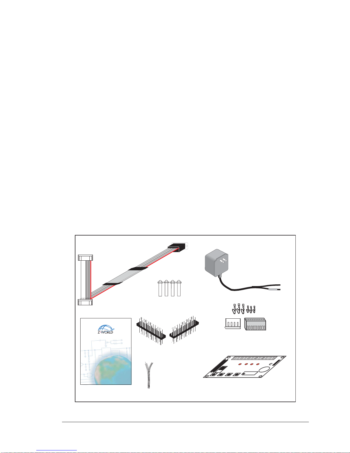
1.3.1 Tool Kit.........................................................................................................................................3
1.3.2 Software........................................................................................................................................4
1.3.3 Additional Tools ...........................................................................................................................4
Chapter 2. Getting Started 5
2.1 Preparing the BL2600 for Development...............................................................................................5
2.2 BL2600 Connections ............................................................................................................................6
2.2.1 Hardware Reset.............................................................................................................................7
2.3 Installing Dynamic C............................................................................................................................8
2.4 Starting Dynamic C ..............................................................................................................................9
2.5 PONG.C..............................................................................................................................................10
2.6 Where Do I Go From Here? ...............................................................................................................10
2.6.1 Real-Time Clock.........................................................................................................................10
Chapter 3. Subsystems 11
3.1 BL2600 Pinouts ..................................................................................................................................12
3.1.1 Connector Options ......................................................................................................................12
3.2 Digital I/O...........................................................................................................................................14
3.2.1 Digital Inputs...............................................................................................................................14
3.2.2 PWM Outputs .............................................................................................................................15
3.2.3 High-Current Digital Outputs .....................................................................................................16
3.2.4 Configurable I/O .........................................................................................................................18
3.3 Serial Communication ........................................................................................................................20
3.3.1 RS-232 ........................................................................................................................................20
3.3.2 RS-485 ........................................................................................................................................20
3.3.3 Programming Port.......................................................................................................................22
3.3.4 Ethernet Port ...............................................................................................................................23
3.4 A/D Converter Inputs..........................................................................................................................24
3.4.1 A/D Converter Calibration..........................................................................................................25
3.5 D/A Converter Outputs.......................................................................................................................26
3.5.1 D/A Converter Calibration..........................................................................................................27
3.6 Analog Reference Voltage Circuit......................................................................................................28
3.7 Programming Cable............................................................................................................................29
3.7.1 Switching Between Program Mode and Run Mode....................................................................29
3.7.2 Detailed Instructions: Changing from Program Mode to Run Mode..........................................29
3.7.3 Detailed Instructions: Changing from Run Mode to Program Mode..........................................29
3.8 Other Hardware...................................................................................................................................30
3.8.1 Clock Doubler.............................................................................................................................30
3.8.2 Spectrum Spreader......................................................................................................................30
3.9 Memory...............................................................................................................................................31
3.9.1 SRAM .........................................................................................................................................31
3.9.2 Flash Memory.............................................................................................................................31
3.9.3 Serial Flash..................................................................................................................................31

Wolf (BL2600)
Chapter 4. Software 33
4.1 Running Dynamic C........................................................................................................................... 33
4.1.1 Upgrading Dynamic C................................................................................................................34
4.2 Sample Programs................................................................................................................................ 35
4.2.1 Digital I/O...................................................................................................................................35
4.2.2 Serial Communication................................................................................................................36
4.2.3 A/D Converter Inputs.................................................................................................................37
4.2.4 D/A Converter Outputs............................................................................................................... 38
4.2.5 Use of BL2600 with SF1000 Serial Flash Card.........................................................................39
4.2.6 TCP/IP Sample Programs...........................................................................................................39
4.3 BL2600 Libraries ............................................................................................................................... 39
4.4 BL2600 Function APIs.......................................................................................................................40
4.4.1 Board Initialization.....................................................................................................................40
4.4.2 Digital I/O...................................................................................................................................41
4.4.3 Serial Communication................................................................................................................49
4.4.4 A/D Converter Inputs.................................................................................................................51
4.4.5 D/A Converter Outputs............................................................................................................... 58
Chapter 5. Using the TCP/IP Features 63
5.1 TCP/IP Connections...........................................................................................................................63
5.2 TCP/IP Sample Programs...................................................................................................................65
5.2.1 How to Set IP Addresses in the Sample Programs.....................................................................65
5.2.2 How to Set Up your Computer’s IP Address for a Direct Connection ...................................... 66
5.2.3 Run the PINGME.C Demo......................................................................................................67
5.2.4 Running More Demo Programs With a Direct Connection ....................................................... 68
5.3 Where Do I Go From Here?...............................................................................................................68
Appendix A. Specifications 69
A.1 Electrical and Mechanical Specifications..........................................................................................70
A.1.1 Exclusion Zone.......................................................................................................................... 72
A.1.2 Headers......................................................................................................................................73
A.2 Conformal Coating............................................................................................................................ 74
A.3 Jumper Configurations ...................................................................................................................... 75
A.4 Use of Rabbit 3000 Parallel Ports ..................................................................................................... 77
Appendix B. Power Supply 79
B.1 Power Supplies..................................................................................................................................79
B.1.1 Power for Analog Circuits.........................................................................................................80
B.2 Batteries and External Battery Connections......................................................................................80
B.2.1 Replacing the Backup Battery ...................................................................................................80
Appendix C. Demonstration Board 81
C.1 Connecting Demonstration Board ..................................................................................................... 81
Appendix D. RabbitNet 85
D.1 General RabbitNet Description .........................................................................................................85
D.2 Physical Implementation...................................................................................................................87
D.2.1 Control and Routing .................................................................................................................. 87
D.3 Function Calls....................................................................................................................................88
D.3.1 Status Byte.................................................................................................................................94
Notice to Users 95
Index 97
Schematics 101

User’s Manual 1
1. INTRODUCTION
The BL2600 is a high-performance, C-programmable single-
board computer that offers built-in digital and analog I/O com-
bined with Ethernet connectivity in a compact form factor. The
BL2600 is ideal for both discrete manufacturing and process-
control applications.
A Rabbit 3000®microprocessor operating at 44.2 MHz provides
fast data processing with 10/100Base-T Ethernet connectivity.
Onboard serial flash options support full directory file structures
to maximize remote access control and programmability. The
I/O can be expanded with RabbitNet peripheral cards.
1.1 BL2600 Description
The BL2600 is an advanced single-board computer that incorporates the powerful Rabbit
3000 microprocessor, flash memory, serial flash, static RAM, digital I/O ports, A/D con-
verter inputs, D/A converter outputs, RS-232/RS-485 serial ports, and a 10/100Base-T
Ethernet port.
1.2 BL2600 Features
•Rabbit 3000®microprocessor operating at 44.2 MHz.
•512K static RAM and 512K flash memory standard
•36 digital I/O: 16 protected digital inputs, 4 high-current digital outputs software-
configurable as sinking or sourcing, and 16 I/O individually software-configurable as
inputs or sinking outputs.
•12 analog channels: eight 11-bit A/D converter inputs, four 12-bit D/A converter 0–10 V
or ±10 V buffered outputs.
•One RJ-45 Ethernet port compliant with IEEE 802.3 standard for 10/100Base-T
Ethernet protocol.
•Three Ethernet status LEDs (BL2600 only).
•Three serial ports (2 RS-232 or 1 RS-232 with RTS/CTS, 1 RS-485 or RS-232).

2Wolf (BL2600)
•Two RabbitNet™ expansion ports.
•Battery-backed real-time clock.
•Watchdog supervisor.
Two BL2600 models are available. Their standard features are summarized in Table 1.
The BL2600 consists of a main board with a RabbitCore module. Refer to the RabbitCore
module manuals, available on Z-World’s Web site, for more information on the Rabbit-
Core modules, including their schematics.
The BL2600 is programmed over a standard PC serial port through a programming cable
supplied with the Tool Kit, and can also be programed through a USB port with an
RS-232/USB converter, or over an Ethernet with the RabbitLink (both available from Z-World).
Appendix A provides detailed specifications.
1.2.1 Connector Options
In addition to the standard polarized friction-lock connectors supplied on BL2600 boards,
dual-entry 0.1" IDC sockets can be used to connect to the BL2600 either from the top or
the bottom.
Table 1. BL2600 Models
Feature BL2600 BL2610
Microprocessor Rabbit 3000®running at
44.2 MHz Rabbit 3000®running at
29.4 MHz
Program Execution SRAM 512K*
* 256K flash/128K SRAM options available for BL2610
Data SRAM 256K —
Flash Memory 512K
Ethernet Port 10/100Base-T, 3 LEDs —
RabbitCore Module Used RCM3200 RCM3100
Visit Z-World’s Web site for up-to-date information about additional add-ons and features
as they become available. The Web site also has the latest revision of this user’s manual.
Standard polarized friction-lock
terminals, 0.1" pitch
0.1" IDC sockets can accept
header pins from either top or
bottom

User’s Manual 3
1.3 Development and Evaluation Tools
1.3.1 Tool Kit
A Tool Kit contains the hardware essentials you will need to use your own BL2600 single-
board computer. The items in the Tool Kit and their use are as follows.
•BL2600 User’s Manual with schematics (this document).
•Dynamic C CD-ROM, with complete product documentation on disk.
•Programming cable, used to connect your PC serial port to the BL2600.
•Power supply, used to power the BL2600
. If you are using another power supply, it must
provide 9 to 36 V DC at 12 W
.
•Stand-offs to serve as legs for the BL2600 board during development.
•Demonstration Board with pushbutton switches and LEDs. The Demonstration Board
can be hooked up to the BL2600 to demonstrate the I/O and the TCP/IP capabilities of
the BL2600.
•Wire assembly to connect Demonstration Board to BL2600.
•Connector pins and parts to build your own wire assemblies: 0.1" crimp terminals;
0.156" crimp terminals; 1 × 4, 1 × 10, and 1 × 13 friction-lock connectors.
•Rabbit 3000 Processor Easy Reference poster.
•Registration card.
Figure 1. BL2600 Tool Kit
Dingo (BL2600)
C-Programmable Single-Board Computer with Ethernet
User’s Manual
019–0138 • 040331–A
PROG
DIAG
Programming
Cable
Plastic Stand-Offs
User's Manual Demo Board
Power Supply
(North American
kits only)
Friction- ock Connectors
& Crimp Terminals
Demo Board
Wiring Harness
·
BUZZER
·
LED4
·
LED3
·
LED2
·
LED1
·
K
·
+5V
·
SW4
·
SW3
·
SW2
·
SW1
·
GND
BUZZER
H1
J1
H2
·
·
1-2
·
·
3-4
·
·
5-6
LED1 LED2 LED3 LED4
SW1 SW2 SW3 SW4
·
·
8-7
·
·
6-5
·
·
4-3
·
·
2-1
DEMO BOARD
Connector Pins

4Wolf (BL2600)
1.3.2 Software
The BL2600 is programmed using version 8.51 or later of Z-World’s Dynamic C. A com-
patible version is included on the Tool Kit CD-ROM.
Z-World also offers add-on Dynamic C modules for purchase containing the popular
µC/OS-II real-time operating system, as well as PPP, Advanced Encryption Standard
(AES), and other select libraries. In addition to the Web-based technical support included
at no extra charge, a one-year telephone-based technical support module is also available
for purchase. Visit our Web site at www.zworld.com or contact your Z-World sales repre-
sentative or authorized distributor for further information.
1.3.3 Additional Tools
Z-World also has available additional programming tools and parts to help you to make
your own wiring assemblies with the friction-lock connectors.
•An RS-232/USB converter cable (Z-World Part No. 540-0070) is available for use with
the programming cable supplied with the Tool Kit. You will need such a converter if
your PC only has a USB port.
•Crimp tool (Z-World Part No. 998-0013) to secure wire in crimp terminals.
Visit our Web site at www.zworld.com or contact your Z-World sales representative or
authorized distributor for further information.

User’s Manual 5
2. GETTING STARTED
Chapter 2 explains how to connect the programming cable and
power supply to the BL2600.
2.1 Preparing the BL2600 for Development
Position the BL2600 as shown below in Figure 2. Attach the four standoffs supplied with
the Tool Kit in the holes at the corners as shown.
Figure 2. Attach Standoffs to BL2600 Board
The standoffs facilitate handling the BL2600 during development, and protect the bottom
of the printed circuit board against scratches or short circuits while you are working with
the BL2600.
J15
J1
AIN0
AIN1
AIN2
AIN3
JP
420 mA
AV0 AV1 AV2 AV3 AI0 AI1 AI2 AI3 AGND GND HOUT0 +HK1 GND HOUT2 +HK3 GND
+HK0 GND HOUT1 +HK2 GND HOUT3
TXC TXF TXE 485 GND
GND RXC RXF RXE 485+
J17
GND HOUT0 +HK1 GND HOUT2 +HK3 GND
+HK0 GND HOUT1 +HK2 GND HOUT3
TXC TXF TXE 485
AIN1 AIN3 AIN5 AIN7 AGND AV1 AV3 AI1 AI3 AGND
AIN0 AIN2 AIN4 AIN AGND AV0 AV2 AI0 AI2 AGND
J11
20
19
R43
JP
R44
R39
R38
R20
R33
R34
U13
R22
R21
R17
C18
C19
U12
R15
C13
R1
C10
R10 U11
J8
R14 R13 C11
AIN0 AIN1 AIN2 AIN3 AIN4 AIN5 AIN AIN7 AGND
C12 R12 R11
U10
BT1
C2
C27
D1
U15
C25
J12
J13
C22
R55R42
C23
C24
R41
R40
R35
R3
R37
U14
R2 R28
R30
R19
R29
R32
R31
R5
R57
L1
R27R25
R23
R24
C20
C21
R18
C1
1
2
25
2
RXE
J14
Q19
D3
Q17 D2 Q18
RXC
D4 Q20 C34
RXF
485+
C35 C3 C37
JP7
485 TERM.
RESISTOR
C30
R58
R59
R 0
U18
C32
C33
RCM2
U17
C31
R9
U1
R8
J10
R7
GND/EGND
RP5
RP
U2
C4
R5
C5
R
C
U4
JA
RCM1
RCM3000 ETHERNET CORE MODULE
U3
RP17 RP18
34
33
1
15 1
2
1
2
15
1
33
34
C1
U1
RP3
RP4
GND
+K
DCIN
+5V
JP3,
JP4
AND
JP4
JP1 AND JP2
GND
+K
DCIN
+5V
J4 RABBITNET 1
J RABBITNET 0
J7
C14
C17
C15
C78
J9
C9U9
RP1
C8
U8
R4
R3
RP15
RP14
RP12
RP13
RP11
R1
R2
C7
U U7
U5
RP8R
P7
RP9
RP10
C2
Q9 Q10
J5
Q12
Q15Q14 Q1
Q11
Q13
C3
Q1 Q2 Q3 Q4 Q5 Q Q7 Q8
JP2
JP1
J1
J2
GND DIN28 DIN24 DIN20 DIN1 GND DIO12 DIO08 DIO04 DIO00
DIN30 DIN2 DIN22 DIN18 +K DIO14 DIO10 DIO0 DIO02 GND
DIN31 DIN27 DIN23 DIN19 +K DIO15 DIO11 DIO07 DIO03 GND
GND DIN29 DIN25 DIN21 DIN17 GND DIO13 DIO09 DIO05 DIO01
GND DIO14 DIO12 DIO10 DIO08 DIO0 DIO04 DIO02 DIO00 GND
+K DIO15 DIO13 DIO11 DIO09 DIO07 DIO05 DIO03 DIO01 GND
GND DIN30 DIN28 DIN2 DIN24 GND DIN22 DIN20 DIN18 DIN1
DIN31 DIN29 DIN27 DIN25 +K DIN23 DIN21 DIN19 DIN17 GND
DIO 0007 PULLS
DIO 0815 PULLS
12
39 40
SW1
J3
1
2
DCIN DCIN GND GND
R111
R112
RESET
RP2
RP1
JP3
DIN 1 19 PULLS
JP4
DIN 2023 PULLS
DIN 2431 PULLS
JP5
R84
C28
1
2
DS1
U1
U
R28
R38
R41
C5
C3
C9
C8
C12
C17
C23 C30
C18
C29 C35
C33
R29
R37
R39
R40
R42
Y3
C42R35
R31
R27
R25
DS1
R7
R70
J4
C79
Y4
C83
C8 GND
R75
R74
R71 DS3
DS2
R 3 R 4
C71
C72
C 8
C 4
C 7
L2
U8
R49
R48
C 2
R51
C1
R44
R47
C59
C49
C57
L1
R 9
R72
R73
C75
C74
R58
C53
C47
C48
C45
C44
C43
JP5
C31
JP3
JP4
C28
C27
C37
C3
C32
R24
R22
C19
R23
C24
R20
C20
R19
C1
C15
R17
R18
R7
R9
R1
R8
C1
R10
R14
C4
SPD LNK ACT
J3
U5
U4
D1
Q1
C39
RP1
RabbitCore
Module

6Wolf (BL2600)
2.2 BL2600 Connections
1. Connect the programming cable to download programs from your PC and to program
and debug the BL2600.
NOTE: Use only the programming cable that has a blue shrink wrap around the RS-232
level converter (Z-World part number 101-0542). If you are using a BL2610, which is
based on the RCM3000, you will need the programming cable that has a red shrink
wrap around the RS-232 level converter (Z-World part number 101-0513). Other
Z-World programming cables might not be voltage-compatible or their connector sizes
may be different.
Connect the 10-pin PROG connector of the programming cable to header J1 on the
BL2600’s RabbitCore module (header J3 for the BL2610 RabbitCore module). Ensure
that the colored edge lines up with pin 1 as shown. (Do not use the DIAG connector, which
is used for monitoring only.) Connect the other end of the programming cable to a COM
port on your PC. Make a note of the port to which you connect the cable, as Dynamic C
will need to have this parameter configured. Note that COM1 on the PC is the default
COM port used by Dynamic C.
Figure 3. Programming Cable Connections
NOTE: Some PCs now come equipped only with a USB port. It may be possible to use
an RS-232/USB converter (Z-World Part No. 540-0070) with the programming cables
mentioned above.
J15
J1
AIN0
AIN1
AIN2
AIN3
JP
420 mA AV0 AV1 AV2 AV3 AI0 AI1 AI2 AI3 AGND GND HOUT0 +HK1 GND HOUT2 +HK3 GND
+HK0 GND HOUT1 +HK2 GND HOUT3
TXC TXF TXE 485 GND
GND RXC RXF RXE 485+
J17
GND HOUT0 +HK1 GND HOUT2 +HK3 GND
+HK0 GND HOUT1 +HK2 GND HOUT3 TXC TXF TXE 485
AIN1 AIN3 AIN5 AIN7 AGND AV1 AV3 AI1 AI3 AGND
AIN0 AIN2 AIN4 AIN AGND AV0 AV2 AI0 AI2 AGND
J11
20
19
R43
JP
R44
R39
R38
R20
R33
R34
U13
R22
R21
R17
C18
C19
U12
R15
C13
R1
C10
R10 U11
J8
R14 R13 C11
AIN0 AIN1 AIN2 AIN3 AIN4 AIN5 AIN AIN7 AGND
C12 R12 R11
U10
BT1
C2
C27
D1
U15
C25
J12
J13
C22
R55 R42
C23
C24
R41
R40 R35
R3
R37
U14
R2 R28 R30
R19
R29
R32
R31
R5
R57
L1
R27R25
R23
R24
C20
C21
R18
C1
1
2
25
2
RXE
J14
Q19
D3
Q17 D2 Q18 RXC
D4 Q20 C34
RXF 485+
C35 C3 C37
JP7
485 TERM.
RESISTOR
C30
R58
R59
R 0
U18
C32
C33
RCM2
U17
C31
R9
U1
R8
J10
R7
GND/EGND
RP5
RP
U2
C4
R5
C5
R
C
U4
JA
RCM1
RCM3000 ETHERNET CORE MODULE
U3
RP17 RP18
34
33
1
15 1
2
1
2
15
1
33
34
C1
U1
RP3
RP4
GND
+K
DCIN
+5V
JP3,
JP4
AND
JP4
JP1 AND JP2
GND
+K
DCIN
+5V
J4 RABBITNET 1
J RABBITNET 0
J7
C14
C17
C15
C78
J9
C9U9
RP1
C8
U8
R4
R3
RP15
RP14
RP12
RP13
RP11
R1
R2
C7
U U7
U5
RP8 RP7
RP9
RP10
C2
Q9 Q10
J5
Q12 Q15Q14 Q1
Q11
Q13
C3
Q1 Q2 Q3 Q4 Q5 Q Q7 Q8
JP2
JP1
J1
J2
GND DIN28 DIN24 DIN20 DIN1 GND DIO12 DIO08 DIO04 DIO00
DIN30 DIN2 DIN22 DIN18 +K DIO14 DIO10 DIO0 DIO02 GND
DIN31 DIN27 DIN23 DIN19 +K DIO15 DIO11 DIO07 DIO03 GND
GND DIN29 DIN25 DIN21 DIN17 GND DIO13 DIO09 DIO05 DIO01
GND DIO14 DIO12 DIO10 DIO08 DIO0 DIO04 DIO02 DIO00 GND
+K DIO15 DIO13 DIO11 DIO09 DIO07 DIO05 DIO03 DIO01 GND
GND DIN30 DIN28 DIN2 DIN24 GND DIN22 DIN20 DIN18 DIN1
DIN31 DIN29 DIN27 DIN25 +K DIN23 DIN21 DIN19 DIN17 GND
DIO 0007 PULLS
DIO 0815 PULLS
12
39 40
SW1
J3
1
2
DCIN DCIN GND GND
R111
R112
RESET
RP2
RP1
JP3
DIN 1 19 PULLS
JP4
DIN 2023 PULLS
DIN 2431 PULLS
JP5
R84
C28
1
2
DS1
U1
U
R28
R38
R41
C5
C3
C9
C8
C12
C17
C23 C30
C18
C29 C35
C33
R29
R37
R39
R40
R42
Y3
C42R35
R31
R27
R25
DS1
R 7
R70
J4
C79
Y4
C83
C8 GND
R75
R74
R71 DS3
DS2
R 3 R 4
C71
C72
C 8
C 4
C 7
L2
U8
R49
R48
C 2
R51
C 1
R44
R47
C59
C49
C57
L1
R 9
R72
R73
C75
C74
R58
C53
C47
C48
C45
C44
C43
JP5
C31
JP3
JP4
C28
C27
C37
C3
C32
R24
R22
C19
R23
C24
R20
C20
R19
C1
C15
R17
R18
R7
R9
R1
R8
C1
R10
R14
C4
SPD LNK ACT
J3
U5
U4
D1
Q1
C39
RP1
DIAG
PROG
Colored edge
To
PC COM port
Programming Cable
PROG
J1
Blue
shrink wrap

User’s Manual 7
2. Connect the power supply to header J12 on the BL2600 as shown in Figure 4. You can
use the crimps and the friction-lock connector included in the Tool Kit to connect the
leads from the power supply, then match the friction lock tab on the friction-lock con-
nector to the back of header J12 on the BL2600 as shown. The friction-lock connector
will only fit one way.
Figure 4. Power Supply Connections
3. Apply power.
Plug in the power supply. The power LED will light up when the BL2600 is powered up
correctly.
CAUTION: Unplug the power supply while you make or otherwise work with the connections
to the headers. This will protect your BL2600 from inadvertent shorts or power spikes.
2.2.1 Hardware Reset
A hardware reset is done by unplugging the power supply, then plugging it back in, or by
pressing the RESET button located just above the RabbitCore module.
J15
J1
AIN0
AIN1
AIN2
AIN3
JP
420 mA
AV0 AV1 AV2 AV3 AI0 AI1 AI2 AI3 AGND GND HOUT0 +HK1 GND HOUT2 +HK3 GND
+HK0 GND HOUT1 +HK2 GND HOUT3
TXC TXF TXE 485 GND
GND RXC RXF RXE 485+
J17
GND HOUT0 +HK1 GND HOUT2 +HK3 GND
+HK0 GND HOUT1 +HK2 GND HOUT3
TXC TXF TXE 485
AIN1 AIN3 AIN5 AIN7 AGND AV1 AV3 AI1 AI3 AGND
AIN0 AIN2 AIN4 AIN AGND AV0 AV2 AI0 AI2 AGND
J11
20
19
R43
JP
R44
R39
R38
R20
R33
R34
U13
R22
R21
R17
C18
C19
U12
R15
C13
R1
C10
R10 U11
J8
R14 R13 C11
AIN0 AIN1 AIN2 AIN3 AIN4 AIN5 AIN AIN7 AGND
C12 R12 R11
U10
BT1
C2
C27
D1
U15
C25
J12
J13
C22
R55 R42
C23
C24
R41
R40
R35
R3
R37
U14
R2 R28
R30
R19
R29
R32
R31
R5
R57
L1
R27R25
R23
R24
C20
C21
R18
C1
1
2
25
2
RXE
J14
Q19
D3
Q17 D2 Q18
RXC
D4 Q20 C34
RXF
485+
C35 C3 C37
JP7
485 TERM.
RESISTOR
C30
R58
R59
R 0
U18
C32
C33
RCM2
U17
C31
R9
U1
R8
J10
R7
GND/EGND
RP5
RP
U2
C4
R5
C5
R
C
U4
JA
RCM1
RCM3000 ETHERNET CORE MODULE
U3
RP17 RP18
34
33
1
15 1
2
1
2
15
1
33
34
C1
U1
RP3
RP4
GND
+K
DCIN
+5V
JP3,
JP4
AND
JP4
JP1 AND JP2
GND
+K
DCIN
+5V
J4 RABBITNET 1
J RABBITNET 0
J7
C14
C17
C15
C78
J9
C9U9
RP1
C8
U8
R4
R3
RP15
RP14
RP12
RP13
RP11
R1
R2
C7
U U7
U5
RP8 RP7
RP9
RP10
C2
Q9 Q10
J5
Q12
Q15Q14 Q1
Q11
Q13
C3
Q1 Q2 Q3 Q4 Q5 Q Q7 Q8
JP2
JP1
J1
J2
GND DIN28 DIN24 DIN20 DIN1 GND DIO12 DIO08 DIO04 DIO00
DIN30 DIN2 DIN22 DIN18 +K DIO14 DIO10 DIO0 DIO02 GND
DIN31 DIN27 DIN23 DIN19 +K DIO15 DIO11 DIO07 DIO03 GND
GND DIN29 DIN25 DIN21 DIN17 GND DIO13 DIO09 DIO05 DIO01
GND DIO14 DIO12 DIO10 DIO08 DIO0 DIO04 DIO02 DIO00 GND
+K DIO15 DIO13 DIO11 DIO09 DIO07 DIO05 DIO03 DIO01 GND
GND DIN30 DIN28 DIN2 DIN24 GND DIN22 DIN20 DIN18 DIN1
DIN31 DIN29 DIN27 DIN25 +K DIN23 DIN21 DIN19 DIN17 GND
DIO 0007 PULLS
DIO 0815 PULLS
12
39 40
SW1
J3
1
2
DCIN DCIN GND GND
R111
R112
RESET
RP2
RP1
JP3
DIN 1 19 PULLS
JP4
DIN 2023 PULLS
DIN 2431 PULLS
JP5
R84
C28
1
2
DS1
Power ED
U1
U
R28
R38
R41
C5
C3
C9
C8
C12
C17
C23 C30
C18
C29 C35
C33
R29
R37
R39
R40
R42
Y3
C42R35
R31
R27
R25
DS1
R 7
R70
J4
C79
Y4
C83
C8 GND
R75
R74
R71 DS3
DS2
R 3 R 4
C71
C72
C 8
C 4
C 7
L2
U8
R49
R48
C 2
R51
C 1
R44
R47
C59
C49
C57
L1
R 9
R72
R73
C75
C74
R58
C53
C47
C48
C45
C44
C43
JP5
C31
JP3
JP4
C28
C27
C37
C3
C32
R24
R22
C19
R23
C24
R20
C20
R19
C1
C15
R17
R18
R7
R9
R1
R8
C1
R10
R14
C4
SPD LNK ACT
J3
U5
U4
D1
Q1
C39
RP1
J12
RESET
+

8Wolf (BL2600)
2.3 Installing Dynamic C
If you have not yet installed Dynamic C version 8.51 (or a later version), do so now by
inserting the Dynamic C CD from the BL2600 Tool Kit in your PC’s CD-ROM drive. The
CD will auto-install unless you have disabled auto-install on your PC.
If the CD does not auto-install, click Start > Run from the Windows Start button and
browse for the Dynamic C setup.exe file on your CD drive. Click OK to begin the
installation once you have selected the setup.exe file.
The online documentation is installed along with Dynamic C, and an icon for the docu-
mentation menu is placed on the workstation’s desktop. Double-click this icon to reach the
menu. If the icon is missing, create a new desktop icon that points to default.htm in the
docs folder, found in the Dynamic C installation folder.
The latest versions of all documents are always available for free, unregistered download
from our Web sites as well.
The Dynamic C User’s Manual provides detailed instructions for the installation of
Dynamic C and any future upgrades.
NOTE: If you have an earlier version of Dynamic C already installed, the default instal-
lation of the later version will be in a different folder, and a separate icon will appear on
your desktop.
Once your installation is complete, you will have up to three icons on your PC desktop.
One icon is for Dynamic C, one opens the documentation menu, and the third is for the
Rabbit Field Utility, a tool used to download precompiled software to a target system.
If you have purchased any of the optional Dynamic C modules, install them after installing
Dynamic C. The modules may be installed in any order. You must install the modules in
the same directory where Dynamic C was installed.

User’s Manual 9
2.4 Starting Dynamic C
Once the BL2600 is connected to your PC and to a power source, start Dynamic C by double-
clicking on the Dynamic C icon or by double-clicking on dcrabXXXX.exe in the Dynamic C
root directory, where XXXX are version-specific characters.
Dynamic C defaults to using the serial port on your PC that you specified during installa-
tion. If the port setting is correct, Dynamic C should detect the BL2600 and go through a
sequence of steps to cold-boot the BL2600 and to compile the BIOS. (Some versions of
Dynamic C will not do the initial BIOS compile and load until the first time you compile a
program.)
If you receive the message No Rabbit Processor Detected, the programming
cable may be connected to the wrong COM port, a connection may be faulty, or the target
system may not be powered up. First, check both ends of the programming cable to ensure
that it is firmly plugged into the PC and the programming port.
If there are no faults with the hardware, select a different COM port within Dynamic C.
From the Options menu, select Communications. Select another COM port from the list,
then click OK. Press <Ctrl-Y> to force Dynamic C to recompile the BIOS. If Dynamic C
still reports it is unable to locate the target system, repeat the above steps until you locate the
active COM port. You should receive a Bios compiled successfully message
once this step is completed successfully.
If Dynamic C appears to compile the BIOS successfully, but you then receive a communi-
cation error message when you compile and load a sample program, it is possible that your
PC cannot handle the higher program-loading baud rate. Try changing the maximum
download rate to a slower baud rate as follows.
•Locate the Serial Options dialog in the Dynamic C Options > Communications
menu. Select a slower Max download baud rate.
If a program compiles and loads, but then loses target communication before you can
begin debugging, it is possible that your PC cannot handle the default debugging baud
rate. Try lowering the debugging baud rate as follows.
•Locate the Serial Options dialog in the Dynamic C Options > Communications
menu. Choose a lower debug baud rate.

10 Wolf (BL2600)
2.5 PONG.C
You are now ready to test your set-up by running a sample program.
Find the file PONG.C, which is in the Dynamic C SAMPLES folder. To run the program,
open it with the File menu (if it is not still open), compile it using the Compile menu, and
then run it by selecting Run in the Run menu. The STDIO window will open and will dis-
play a small square bouncing around in a box.
This program shows that the CPU is working. The sample program described in
Section 5.2.3, “Run the PINGME.C Demo,” tests the TCP/IP portion of the board.
2.6 Where Do I Go From Here?
NOTE: If you purchased your BL2600 through a distributor or Z-World partner, contact
the distributor or Z-World partner first for technical support.
If there are any problems at this point:
•Check the Z-World Technical Bulletin Board at www.zworld.com/support/bb/.
•Use the Technical Support e-mail form at www.zworld.com/support/.
If the sample program ran fine, you are now ready to go on to explore other BL2600 fea-
tures and develop your own applications.
Chapter 3, “Subsystems,” provides a description of the BL2600’s features, Chapter 4,
“Software,” describes the Dynamic C software libraries and introduces some sample pro-
grams, and Chapter 5, “Using the TCP/IP Features,” explains the TCP/IP features.
2.6.1 Real-Time Clock
If you plan to use the real-time clock functionality in your application, you will need to set
the real-time clock. You may set the real-time clock using the SETRTCKB.C sample pro-
gram from the Dynamic C SAMPLES\RTCLOCK folder. The RTC_TEST.C sample pro-
gram in the Dynamic C SAMPLES\RTCLOCK folder provides additional examples of how
to read and set the real-time clock

User’s Manual 11
3. SUBSYSTEMS
Chapter 3 describes the principal subsystems for the BL2600.
•Digital I/O
•Serial Communication
•A/D Converter Inputs
•D/A Converter Outputs
•Analog Reference Voltage Circuit
•Memory
Figure 5 shows these Rabbit-based subsystems designed into the BL2600.
Figure 5. BL2600 Subsystems
SRAM
32 kHz
osc
RabbitCore Module
RABBIT
3000
Battery-Backup
Circuit
Ethernet
Program
F ash
Seria
F ash
22.1 MHz
osc
RS-232
RS-485
Data
Register
Data
Register
A/D
Converter
D/A
Converter
High-Current
Outputs
RabbitNet
Digita
Inputs
Configurab e
I/O
Data
Register

12 Wolf (BL2600)
3.1 BL2600 Pinouts
The BL2600 pinouts are shown in Figure 6(a) and Figure 6(b).
Figure 6(a). BL2600 Pinouts (friction-lock connectors)
3.1.1 Connector Options
Standard BL2600 models are equipped with two 1 × 20 friction-lock connector terminals
(J1 and J2), two polarized 1 × 9 friction-lock connector terminals (J8 and J15), one 1 × 13
friction-lock connector terminal (J16), and one 1 × 10 friction-lock connector terminal
(J17); all of these friction-lock connector terminals have a 0.1" pitch.
The RJ-45 jacks at J4 and J6 labeled RabbitNet are serial I/O expansion ports for use with
RabbitNet peripheral expansion boards. The RabbitNet jacks do not support Ethernet con-
nections. Be careful to make your Ethernet connection to the jack labeled Ethernet in the
above diagram (note that BL2610 models do not have an Ethernet port).
J15
DCIN
DCIN
GND
GND
J16
AV0 AV1 AV2 AV3 AI0 AI1 AI2 AI3 AGND GND HOUT0 +HK1 GND HOUT2 +HK3 GND
+HK0 GND HOUT1 +HK2 GND HOUT3
TXC TXF TXE 485 GND
GND RXC RXF RXE 485+
J17
J12
J5
J1 J2
U1
U
R28
R38
R41
C5
C3
C9
C8
C12
C17
C23 C30
C18
C29 C35
C33
R29
R37
R39
R40
R42
Y3
C42R35
R31
R27
R25
DS1
R 7
R70
J4
C79
Y4
C83
C8 GND
R75
R74
R71 DS3
DS2
R 3 R 4
C71
C72
C 8
C 4
C 7
L2
U8
R49
R48
C 2
R51
C 1
R44
R47
C59
C49
C57
L1
R 9
R72
R73
C75
C74
R58
C53
C47
C48
C45
C44
C43
JP5
C31
JP3
JP4
C28
C27
C37
C3
C32
R24
R22
C19
R23
C24
R20
C20
R19
C1
C15
R17
R18
R7
R9
R1
R8
C1
R10
R14
C4
SPD LNK ACT
J3
U5
U4
D1
Q1
C39
RP1
J8
High-Current
Digital Outputs
Analog
Ground
Analog
Outputs
Battery
AIN0
AIN1
AIN2
AIN3
AIN4
AIN5
AIN
AIN7
AGND
Analog
Inputs
RabbitNet
J6
J4
J7
GND
GND
DIO00
DIO01
DIO02
DIO03
DIO04
DIO05
DIO0
DIO07
DIO08
DIO09
DIO10
DIO11
DIO12
DIO13
DIO14
DIO15
GND
+K
GND
DIN1
DIN17
DIN18
DIN19
DIN20
DIN21
DIN22
DIN23
GND
+K
DIN24
DIN25
DIN2
DIN27
DIN28
DIN29
DIN30
DIN31
GND
Configurable I/O Digital Inputs Digital Inputs
Analog
Ground
Ethernet
AV0
AV1
AV2
AV3
AI0
AI1
AI2
AI3
AGND
Power
Supply
GND
+HK0
HOUT0
GND
+HK1
HOUT1
GND
+HK2
HOUT2
GND
+HK3
HOUT3
GND
VOLTAGE CURRENT
0 1 2 3
GND
TxC
RxC
TxF
RxF
TxE
RxE
485
485+
GND
RS-232
RS-485
+K +K

User’s Manual 13
Two 4-pin 0.156" friction-lock connector terminals at J5 and J7 are installed to supply
power (DCIN and +5 V) to the RabbitNet peripheral expansion boards. The 4-pin 0.156"
friction-lock connector terminal at J12 is for the main power supply connections.
The BL2600 also has 2 × 20, 2 × 13, 2 × 10, and 2 × 7 IDC sockets with a pitch of 0.1" in
addition to the friction-lock connectors. Corresponding headers or ribbon cables may be
plugged into these sockets from either the top or the bottom. A top view of the pinouts for
these sockets is shown in Figure 6(b).
Figure 6(b). BL2600 Pinouts (IDC sockets)
NOTE: Remember that the pinouts will mirror those shown above when they are viewed
from the other side of the board.
DCIN
DCIN
GND
GND
J13
J12
J5
J3
J11 J14
U1
U
R28
R38
R41
C5
C3
C9
C8
C12
C17
C23 C30
C18
C29 C35
C33
R29
R37
R39
R40
R42
Y3
C42R35
R31
R27
R25
DS1
R 7
R70
J4
C79
Y4
C83
C8 GND
R75
R74
R71 DS3
DS2
R 3 R 4
C71
C72
C 8
C 4
C 7
L2
U8
R49
R48
C 2
R51
C 1
R44
R47
C59
C49
C57
L1
R 9
R72
R73
C75
C74
R58
C53
C47
C48
C45
C44
C43
JP5
C31
JP3
JP4
C28
C27
C37
C3
C32
R24
R22
C19
R23
C24
R20
C20
R19
C1
C15
R17
R18
R7
R9
R1
R8
C1
R10
R14
C4
SPD LNK ACT
J3
U5
U4
D1
Q1
C39
RP1
High-Current
Digital Outputs
Analog
Ground
Analog
Outputs
Battery
Analog
Inputs
RabbitNet
J6
J4
J7
GND
DIO01
DIO03
DIO05
DIO07
DIO09
DIO11
DIO13
DIO15
GND
+K
DIN17
DIN19
DIN21
DIN23
DIN25
DIN27
DIN29
DIN31
GND
Configurable
I/O Digital Inputs
Ethernet
AIN0
AIN2
AIN4
AIN
AGND
AV0
AV2
AI0
AI2
AGND
Power
Supply
GND
+HK0
HOUT0
GND
+HK1
HOUT1
GND
+HK2
HOUT2
GND
+HK3
HOUT3
GND
VOLTAGE
CURRENT
0 1 2 3
TxC
GND
TxF
GND
TxE
GND
485
RS-232
RS-485
+K
GND
DIO00
DIO02
DIO04
DIO0
DIO08
DIO10
DIO12
DIO14
GND
+K
DIN1
DIN18
DIN20
DIN22
DIN24
DIN2
DIN28
DIN30
GND
AIN1
AIN3
AIN5
AIN7
AGND
AV1
AV3
AI1
AI3
AGND
RxC
GND
RxF
GND
RxE
GND
485+
Analog
Ground
TOP VIEW
GND
+HK0
HOUT0
GND
+HK1
HOUT1
GND
+HK2
HOUT2
GND
+HK3
HOUT3
GND

14 Wolf (BL2600)
3.2 Digital I/O
3.2.1 Digital Inputs
The BL2600 has 16 digital inputs, DIN16–DIN31, each of which is protected over a range
of –36 V to +36 V. The inputs are factory-configured to be pulled up to +5 V, but they can
also be pulled up to +K or DCIN, or pulled down to 0 V in banks by changing a jumper as
shown in Figure 7.
Figure 7. BL2600 Digital Inputs DIN16–DIN31 [Pulled Up—Factory Default]
Table 2 lists the banks of digital inputs and summarizes the jumper settings.
When you use the software digIn function call to read the digital inputs, DIN16–DIN31
are considered to be digital input channels 16–31.
Table 2. Banks of BL2600 Digital Inputs
Digital Inputs Header Pins Jumpered Pulled Up/Pulled Down
DIN16–DIN19 JP3 1–2 Inputs pulled up to +5 V
DIN20–DIN23 JP4 3–4 Inputs pulled up to DCIN
DIN24–DIN31 JP5 5–6 Inputs pulled up to +K
7–8 Inputs pulled down to GND
100 kW
27 kW
GND
+K
DCIN +5 V
Rabbit 3000®
Microprocessor
+3.3 V

User’s Manual 15
The actual switching threshold is approximately
1.40 V. Anything below this value is a logic 0,
and anything above is a logic 1. The digital inputs
are each fully protected over a range of -36 V to
+36 V, and can handle short spikes of ±40 V.
NOTE: If the inputs are pulled up to +K or
to DCIN, the voltage range over which
the digital inputs are protected changes
to +K (or DCIN) – 36 V to +36 V.
Individual DIN16–DIN23 channels may be used
for interrupts, input capture, as quadrature decod-
ers, or as PWM outputs.
The use of these channels for interrupts, input
capture, and as quadrature decoders is described
in the Rabbit 3000 Microprocessor User’s Manual,
and is illustrated through sample programs in the
Dynamic C SAMPLES\RABBIT3000 folder. Table 3 lists these alternate uses.
3.2.2 PWM Outputs
Digital inputs DIN20–DIN23 can be used as PWM output channels by setting the jumper
on header JP4 across pins 7–8 to pull the digital inputs to ground. Once the PWM driver
sets up a given PWM channel, the corresponding digital input channel is no longer avail-
able for use as a digital input. The output voltage swing will be 0 to 2.5 V, which is suitable
for interfacing only to CMOS-level inputs. Since the output impedance is approximately
27 kΩ, the input impedance of the circuit the PWM output is connected to should be at
least 10 times as high.
The sample program PWM.C in the IO subdirectory in SAMPLES\BL2600 shows how to
set up and use the PWM outputs.
Table 3. Alternate Uses for BL2600 Channels DIN16–DIN23
Channel Interrupt Input Capture Quadrature
Decoder PWM Outputs
DIN16 ×
DIN17 ×
DIN18 ×
DIN19 ××
DIN20 ××
DIN21 ×××
DIN22 ××
DIN23 ×××
Figure 8. BL2600 Digital Input
Protected Range
+40 V
+3 V
+3.3 V
40 V
Normal Switching
evels
Spikes
Digital Input Voltage
Spikes
Spikes

16 Wolf (BL2600)
3.2.3 High-Current Digital Outputs
The BL2600 has four high-current digital outputs, HOUT0–HOUT3, which can each sink
or source up to 2 A. Figure 9 shows a wiring diagram for using the digital outputs in either
a sinking or a souring configuration.
Figure 9. BL2600 High-Current Digital Outputs
All the digital outputs sink and source actively. They can be used as high-side drivers, low-
side drivers, or as an H-bridge driver. When the BL2600 is first powered up or reset, all
the outputs are disabled, that is, at a high-impedance tristate, until the digHoutConfig
software function call is made. The digHoutConfig call sets the initial state of each
high-current output according to the configuration specified by the user, and enables the
digital outputs to their initial status.
Table 4. BL2600 High-Current Outputs Logic States
U3 Output High-Current Output
A B
High High Prohibited
(defaults to sourcing)
High Low Sourcing
Low High Sinking
Low Low High-impedance (tristate)
+HKx
100 kW
330 W
10 kW
10 kW
27 kW
1 nF
100 kW
1 nF
MMBT4401
B
A
(in sinking
mode)
(in sourcing
mode)
Table of contents
Other Z-World Motherboard manuals