Zamel GPRN User manual

ZAMEL Sp. z o.o.
ul. Zielona 27, 43-200 Pszczyna, Poland
tel. +48 32 449 15 00, +48 32 210 46 65, fax +48 (32) 210 80 04
www.zamel.com, e-mail: [email protected]
plik: inst_gb_GPRN | modykacja: 31.03.2016 plik: inst_gb_GPRN | modykacja: 31.03.2016
A DRAFT OR A PICTURE OF THE HEATING CABLE, SUPPLY TABLE AND ACCESSORIES
DESCRIPTION
Heating cables type GPRN are used to protect gutters and drain pipes against de-icing. They are
resistant to UV radiation and are laid in gutters in pairs or individually. They are xed by additional
accessories (clips for gutters, clips for drain pipes, suspensions and chains). The cables must be
mounted with a temperature controller, equipped with a temperature sensor or ice and snow sensors.
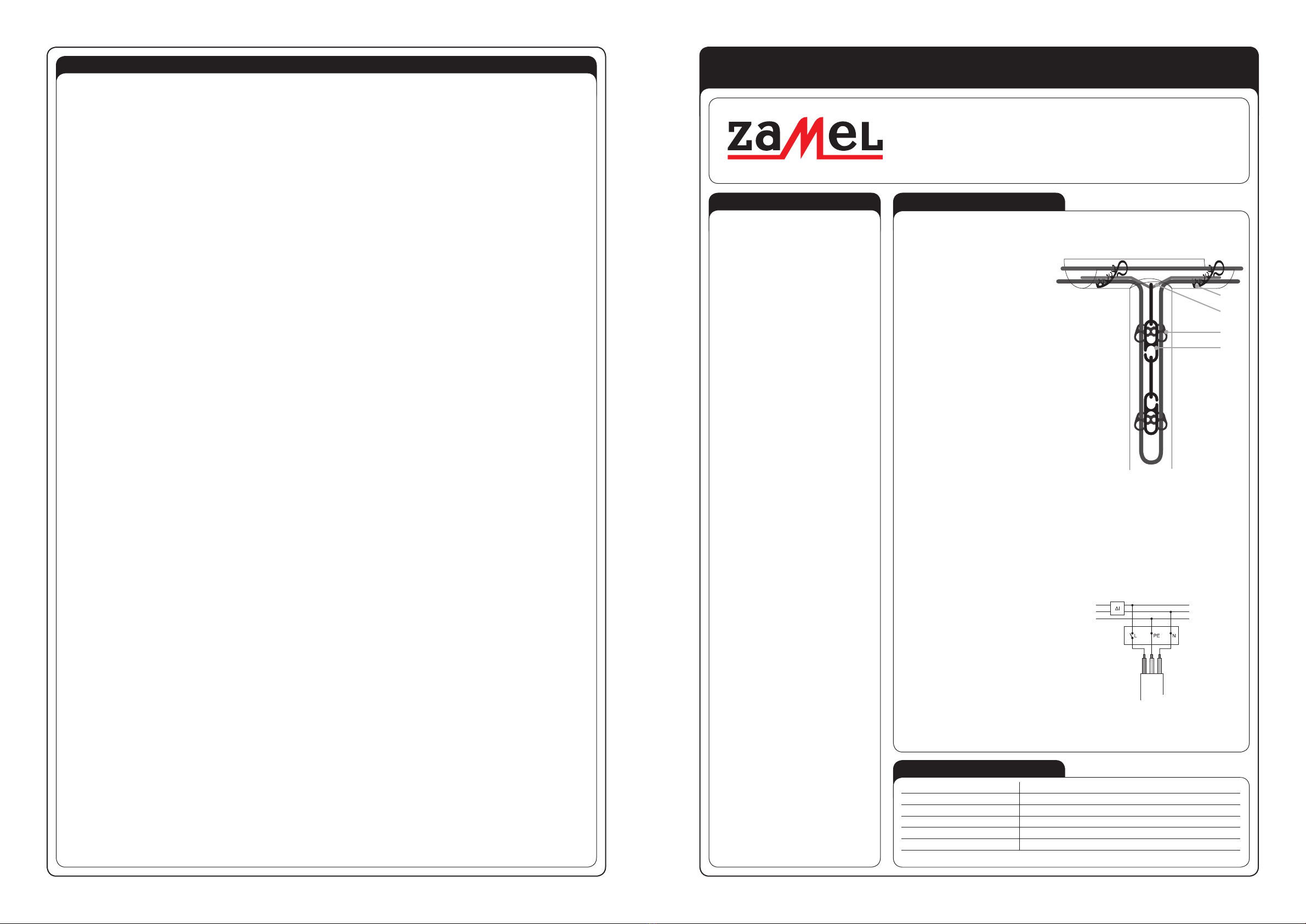
The arrangement and application of particu-
lar accessories are shown below.
• The GPRN heating cables are designed
to operate outdoor. They are prepared to
operate at 230 V AC nominal voltage and
18 W/m power.
• The heating cable is connected with po-
wer supply cable, which by means of a
temperature controller is connected to
230 V AC.
• The device should be connected accor-
ding to the details included in this ope-
rating manual. Installation, connection
and control should be carried out by a
qualied electrician staff, who act in ac-
cordance with the service manual and the
device functions. Before installation make
sure the connection cables are not under
voltage.
• Improper transport, storage, and use of
the device inuence its wrong functioning.
It is not advisable to install the device in
the following cases: if any device part is
missing or the device is damaged or de-
formed. In case of improper functioning of
the device contact the producer.
GPRN heating cable - set includes:
• one-sided power supply heating cable connected with power supply cable,
• installation instruction with the Warranty Card.
A temperature controller is an essential element used to control the GPRN heating cable. It is used
to connect the heating cable with electric installation. It is important to choose a correct temperature
controller with regard to the application of a heating cable and its function. The ZAMEL Sp. z o.o.
company offers the application of temperature controllers by EBERLE.
It is advisable to choose a temperature control-
ler in accordance to power of the connected
heating cable as well as to the placement of
the heating cable and measurement probes.
To control temperature, a controller keeping a
constant temperature or a controller with a pro-
grammer needs to be used and which allows
for the adjustment of heating parameters.
Depending on the function the heating system
with a temperature controller shall realise, the
following sensors are applied: temperature
sensors, ice and snow sensors, temperature
and humidity sensors.
The connection of the heating cable with
a temperature controller should be done
in accordance with a diagram described
in the temperature controller manual in-
struction.
REMARKS
• During installation it is required to follow in-
structions included in the Heating Cable Ma-
nual Instruction.
• Temperature controller’s installation must be
done according to temperature controller In-
stallation Manual.
• It is forbidden to mount the cable on pins,
bolts, screws or other xing elements that
can damage the outer coating of cables.
• The cable installation surface must be smo-
oth with no sharp edges or sharp xing ele-
ments.
• Heating unit cannot be mounted on non-uni-
form bases.
• Heating cable should not be installed in pla-
ces with permanent building.
• Heating cable resistance should be measu-
red twice: after opening the package and
before installers’ work and also after placing
the heating cable in an appropriate place.
• Ensure the sub-oor is dust and sharp ele-
ments free.
• Don’t install the heating cable if the ambient
temperature is below + 5°C.
• Don’t cut the heating cable or its connection
with power supply cable.
• The heating cable should not undergo exces-
sive strain and should be protected against
sharp device damage.
• Heating unit must be supplied by means of
a device from TN-S electric circuit with RCD
(residual current device) of nominal power
supply lower than 30 mA. The installation
should have surge protection.
• The heating cables must not come into con-
tact, cross with each other or other cables
- this could damage the insulation. The mi-
nimum distance between the heating cables
must not be less than 5-times the diameter.
• It is required to make a draft or add pictures
of arrangement of the heating cable, power
supply cable and the connection place of the
heating cable with power cable („cold wire”).
The draft or pictures are an integral part of
the as-built documentation.
• The non-detachable supply cable cannot be
replaced. If the cord is damaged, the equip-
ment is useless. The power supply cable can
be shortened to the desired length, necessa-
ry for mounting the temperature controller.
• The device is not intended to be used by pe-
ople (children) with limited physical, feeling
or psychic ability or people without experien-
ce or without the device knowledge unless it
is under supervision of a person responsible
for safety or according to installation manual.
• Pay attention to children - they must not play
with the device.
• The radius of heating cable bending shall not
be less than 8 times of its diameter.
• The heating cable cannot be permanently
immersed in any liquid.
• The heating cable must be used in accordan-
ce with manufacturer’s specications.
TECHNICAL DATA
Heating cable TYPE GPRN 12 ÷ 100 m long
Power supply voltage: 230 V AC / 50 Hz
Unit power: 18 W/m
Operating temperature: 80 oC
Supply type: one-sided
Heating cable: two-wire, shielded
The heating cable is ended with H05VV-F 3G1 power supply cable at one side
MATEC – ELECTRIC DE-ICING SYSTEMS MANUAL INSTRUCTION
HEATING DE-ICING CABLE TYPE GPRN FOR GUTTERS AND DRAIN PIPES
230 V AC
RCD
protection device
L(black / brown)
N(blue)
PE (green-yellow )
brown
green-yellow
blue
Temperature
controller
Supply cable
of the one-sided
supplied
heating cable.
Fig. A connection diagram of a heating cable
by means of a temperature controller
to the electrical installation
Fig. Arrangement and application of accessories
KRS-01
ZW-01
KRU-01
LS-01

plik: inst_gb_GPRN | modykacja: 31.03.2016 plik: inst_gb_GPRN | modykacja: 31.03.2016
INSTALLATION
1. Before purchase, measure the surface the heating cable will be applied to.
2. Choose a cable of an appropriate length. If the width / diameter of the gutter / drain pipe does not exceed 80 mm, a single arrangement of the heating
cable may be used. In case this width / diameter is bigger than the recommended one, it is advisable to arrange the cables in a pair while maintaining
the minimum 45 mm distance between the cable runs. The heating cable in the downpipe should be selected that it is 1 meter below ground level. This
will allow the water outow safely eg for drainage wells.
3. Unpack particular elements and inspect visually of what you have received.
4. Make a draft of the heating cable arrangement in a drain pipe / gutters. Specify and mark the installation place of the temperature controller and electric
supply as well as of sensors used with the controller. A draft or pictures are an integral part of the as-built documentation.
5. Check the heating cable resistance with the supply cable based on the value given on the label. Write it down in the Warranty Card.
6. Prepare the connection place of the heating cable and a temperature controller to the electrical installation.
7. Prepare the protection corrugated pipes for the separate insertion of: a supply cable of the heating cable and a sensor’s signalling cable.
8. Before the heating cable arrangement make sure the surface is free of dust and sharp elements.
9. In order to prevent the heating cables from contact in a gutter, mount clips (type: KRU-01) inside gutters every 25 cm.
10. Then insert the heating cable into the clips. During installation the cable outer insulation must not be damaged.
Fig. A diagram of arranging a clips KRU-01 in a gutter with a hating cable
11. In case of mounting the heating cable in a drain pipe before insertion of the heating cable the following should be done:
a) Put a suspension ZW-01 on a drain. The suspension can be shortened depending on to the dimensions of the drainage system.
b) Attach a chain LS-01 to the suspension, which together with a cable should run along the drain pipe till its end (bottom).
c) Attach a KRS-01 clip used for drain pipes to the LS-01 chain.
d) Attach the heating cable to the KRS-01 clips. It is important that the cable is laid at the whole length of the gutter – to the bottom.
Fig. A diagram of a heating cable arrangement and equipment in a drain pipe
12. The heating cable must not be shortened. Its excess length should be lain down as an additional cable run. (keeping the minimum 45 cm distance).
13. The supply cable and cables from the sensors should be pulled through in a separate protection corrugated pipe and install the temperature controller in a
previously arranged place. To pull cables through a protection corrugated pipe use the so called „pilote”. In order to avoid damaging the cables’ connection
with the heating cable do not pull or stretch them, etc.
14. Carry out the second resistance measurement just after the heating cable has been mounted but before connecting it to the temperature controller and
write the results in the Warranty Card.
Connection of the heating cable to the electrical installation should be carried out by a qualied electrician staff with suitable authorisations.
The installation should be in accordance with standards valid in a particular country.
The electrical installation, the GPRN heating cable is connected to with a supply cable,
should be made in accordance with applicable national regulations.
WARRANTY
WARRANTY CARD
Zamel Sp. z o.o. declares and assures that the electric heating systems MATEC (heating cables) manufactured and supplied by Zamel Sp. z o.o. are com-
pliant with current standards in the Company and binding norms in Poland. The warranty includes all MATEC products under the condition of proper storage,
transport, installation and operation according to binding norms. There is 2 year warranty for MATEC products and the warranty refers to defects made by
the manufacturer itself.
GENERAL WARRANTY CONDITIONS AND CLAIM CONSIDERATION BY Zamel Sp. z o.o.
1. Zamel Sp. z o.o. assures warranty for MATEC products. There is 2 year warranty for the heating cables. Warranty time starts at the moment of product sell
by Zamel Sp. z o.o. to the Purchaser. Be able to provide as a proof of purchase of the product an invoice by Zamel Sp. z o. o.
2. Zamel Sp. z o.o. shall process the claim at its own discretion.
3. The purchaser must inform about the claim which will be considered within 14 workdays only after proper claim notication. The PURCHASER shall lay
any claims in writing to the Authorised Point or Zamel Sp. z o.o. only on presentation of an invoice (or its number and date of issue)
4. The properly lled Warranty Card should include (the scheme or photos):
• installed heating cable with supply cable (including distances between the places of the heating cable) and arrangement of joints (a part connecting the
heating cable with the supply cable),
• installation place of the temperature controller, connection of the supply cable „cold” to the thermocontroller,
• location of control sensors and thermocontroller control and their connection to the electrical installation.
5. In case it appears that Zamel Sp. z o.o. is not the manufacturer of the claimed product or in case the claim is deemed void by Zamel Sp. z o.o., the Pur-
chaser will bear all the costs connected with claim consideration.
6. When your Warranty is invoked, your damaged product will be replaced free of charge to yourself by Zamel Sp. z o.o.
7. The manufacturer warranty is not valid in below cases:
• damage caused by unauthorised modications made by the PURCHASER or any third parties to the product
• mechanical damage of the device
• wrong power supply
• electric installation which is not compliant with current IEE wiring regulations and installations
• damage caused by incorrect product mounting - not according with MATEC Installation Manual.
8. In case of product claim by an indirect Purchaser of Zamel products, the Purchaser is obliged to present the claim to the Supplier (where the product was
purchased).
ZAMEL sp. z o.o.
Installation place
Post code, city/town
Street, Home/Flat No
Telephone
Filled by the electrician
Electrician Name/Surname
Telephone
No of a Certied Electrician /
Expire date of a Certied Electrician
Installation date
Resistance measurement results of the Heating Cable:
After the package was opened
(before installation) [Ω]:
After laying the heating cable
(before connection t the tempe-
rature controller) [Ω]:
Signature / stamp Place for the Heating Mat label
OPERATION
• Before starting the seasonal heating sys-
tem, visual inspection of the heating and
power cable shouLd be done in order to eli-
minate the risk of faulty wiring operation.
• The heating system operation is limited to
switching on the temperature controller and
to adjust the required parameters.
The device is designed for single-phase installation and must be installed in accordance
with standards valid in a particular country. The device should be connected according to
the details included in this operating manual. Installation, connection and control should be
carried out by a qualied electrician staff, who act in accordance with the service manual
and the device functions. Before installation make sure the connection cables are not under voltage.
Improper transport, storage, and use of the device inuence its wrong functioning. It is not advisable
to install the device in the following cases: if any device part is missing or the device is damaged or
deformed. In case of improper functioning of the device contact the producer.
The symbol means selective collecting of electrical and electronic equipment.
It is forbidden to put the used equipment together with other waste.
UWAGA
KRU-01
Gutter
Heating cable
Heating cable
KRS-01
ZW-01
LS-01
This manual suits for next models
10
Other Zamel Cables And Connectors manuals
Popular Cables And Connectors manuals by other brands

Larson Electronics
Larson Electronics EPCO-20A Series INSTALLATION, OPERATION & MAINTENANCE DATA SHEET

Midland
Midland 70-1308A Service and instruction manual

ELEKTRA
ELEKTRA TuffTec 30 installation manual

Speaka Professional
Speaka Professional HDMIV-IPSO100 operating instructions

Explore
Explore EP9134 user guide

Meltric
Meltric DR Series operating instructions