Zamel GPSY User manual

ZAMEL Sp. z o.o.
ul. Zielona 27, 43-200 Pszczyna, Poland
tel. +48 32 449 15 00, +48 32 210 46 65, fax +48 (32) 210 80 04
www.zamel.com, e-mail: [email protected]
plik: inst_zamel_gb_GPSY | modykacja: 07.06.2016 plik: inst_zamel_gb_GPSY | modykacja: 07.06.2016
A DRAFT OR A PHOTO OF THE HEATING CABLE WITH A SUPPLY CABLE AND ACCESSORIES
DESCRIPTION
Heating cables type GPSY are used against icing for stairs and ramps. They are laid under the
outdoor surfaces. These cables must not be applied under asphalt. They are strongly mounted to
the surface by means of mounting clips. The cables should be installed with a temperature regulator
equipped with sensors.
The GPSY heating cables are designed to operate outdoor at 230 V AC nominal voltage and 20 W/m.
The heating cable with power supply cable is connected to 230 V AC by means of a temperature
regulator.
GPSY heating cable – the set includes:
● one-sided power supply heating cable with power supply cable,
● installation instruction with the Warranty Card.
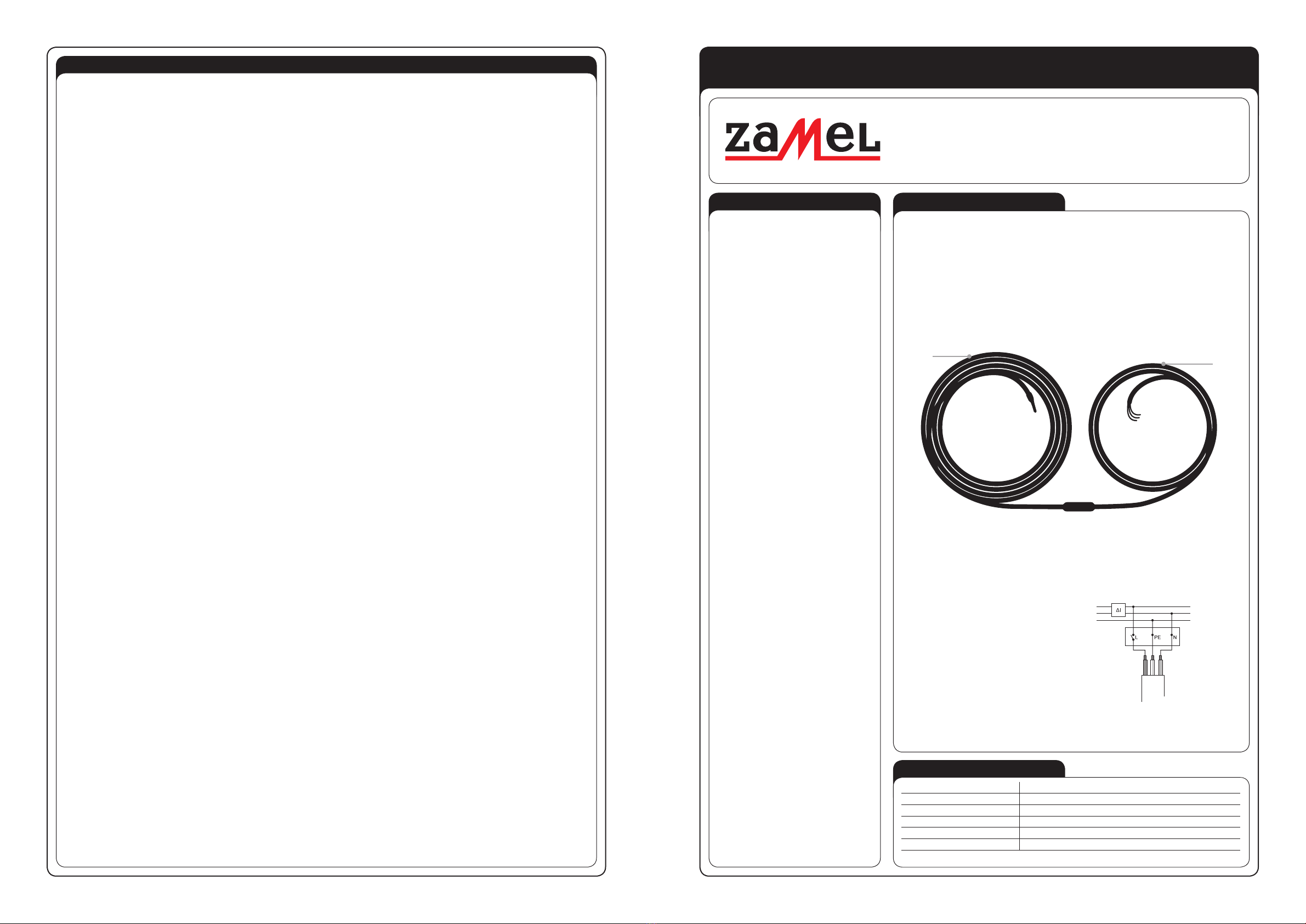
Fig. Heating cable with supply cable
A temperature regulator is an essential ele-
ment used to control the GPSY heating cable
temperature. It is used to connect the heating
cable with the electric installation.
It is import ant to choose a temperature regula-
tor with regard to the heating cable power, its
location place and with regard to the place of
the measuring sensors.
Depending on the function the heating system
with a temperature regulator shall realise, the
following sensors are applied: temperature
sensors, ice and snow sensors, temperature
and humidity sensors.
The connection of the heating cable with a
temperature regulator should be done in ac-
cordance with a diagram described in the
temperature regulator manual instruction.
REMARKS
• During installation it is required to follow
instructions included in the Heating Cable
Manual Instruction.
• Thermoregulator’s installation must be done
according to Thermoregulator Installation
Manual.
• It is forbidden to mount the cable on pins,
bolts, screws or other xing elements that
can damage the outer jacked of cables.
• The cable installation surface must be
smooth with no sharp edges or sharp xing
elements.
• Heating unit cannot be mounted on non-uni-
form bases.
• The heating cables should be installed be-
tween the expansion joints, it means one
heating cable module per one plate.
• The resistance heating cable should not be
installed in places with permanent building.
• The heating cable resistance must be meas-
ured at least twice: before starting the instal-
lation works, after arranging the heating ca-
ble on the oor, and before covering it with
the top oor layer.
• Installation of the heating cable in the ambi-
ent temperature below + 5°C is not advis-
able.
• Don’t cut the heating cable or its connection
with power supply cable. Only the supply ca-
ble can be shortened.
• The heating cable should not undergo exces-
sive strain and should be protected against
sharp device damage.
• Heating unit must be supplied by means of
a device from TN-S electric circuit with RCD
(residual current device) of nominal power
supply lower than 30 mA. The installation
should have surge protection.
• The heating cables must not come into con-
tact, cross with each other or other cables
- this could damage the insulation. The mini-
mum distance between the heating cables
must not be less than 6 cm.
• It is required to make a draft or add pictures
of the arrangement of the heating cable,
power supply cable and the connection place
of the heating cable with power cable („cold
wire”). The draft or pictures are an integral
part of the as-built documentation.
• The device is not intended to be used by peo-
ple (children) with limited physical, feeling or
psychic ability or people without experience
or without the device knowledge unless it is
under supervision of a person responsible for
safety or according to installation manual.
• Pay attention to children - they must not play
with the device.
• The radius of heating cable bending shall not
be less than 10 times of its diameter.
• The heating cable cannot be permanently im-
mersed in any liquid.
• The heating cable must be used in accord-
ance with manufacturer’s specications.
• The cable is not designed to be applied un-
der asphalt surface.
TECHNICAL DATA
Heating cable TYPE GPSY 9,5 ÷ 100 m long
Power supply voltage: 230 V AC / 50 Hz
Unit power: 20 W/m
Operating temperature: 80 oC
Supply type: one-sided
Heating cable: two-wire, shielded
The heating cable is ended with H05VV-F 3G1 power supply cable at one side
MATEC – ELECTRIC DE-ICING SYSTEMS MANUAL INSTRUCTION
HEATING CABLE TYPE GPSY, USED UNDER DRIVEWAYS AND OTHER TRANSPORT ROUTES FOR STAIRS AND RAMPS
230 V AC
RCD
protection device
L(black / brown)
N(blue)
PE (green-yellow )
brown
green-yellow
blue
Temperature
controller
Supply cable
of the one-sided
supplied
heating cable.
Fig. A connection diagram of a heating cable
by means of a temperature regulator
to the electrical installation
Heating
cable Supply
cable

plik: inst_zamel_gb_GPSY | modykacja: 07.06.2016 plik: inst_zamel_gb_GPSY | modykacja: 07.06.2016
INSTALLATION
1. Before purchase, measure the surface the heating cable will be applied to.
2. Choose a heating cable of an appropriate length and expected heating power. The distance between successive runs of the heating cable must not be
less than 6 cm.
3. Make a draft of the heating cable arrangement. Specify and mark the installation place with the temperature regulator, electric supply and sensors of the
temperature regulator. A draft or pictures are an integral part of the as-built documentation.
4. Unpack particular elements and inspect visually of what you have received.
5. Check the heating cable resistance with the supply cable based on the value given on the label. Write it down in the Warranty Card.
6. Prepare the connection place of the heating cable and a temperature regulator to the electrical installation.
7. Prepare the protection corrugated pipes for the separate insertion of: a supply cable of the heating cable and a sensor’s signalling cable.
8. Clean the oor of sharp and dangerous items.
9. Unfold the mounting tape type TMS-01 on the surface, where the heating cable will be arranged and attach it to the oor. The recommended distance
between mounting clips of the heating cable should not be more than 25 cm. The radius of the heating cable bending shall not be less than 10 times of
its diameter.
10. Place the heating cable on the previously prepared surface and grasp it by means of “inner clamps” of the mounting clip. The heating cable should be laid
along the edges in a previously carved groove. This protects the cable from damage of the outer coating. Do not pull or stretch the wires in order to avoid
damage of the cold „joint” connection of the supply cable with the heating cable. In order to effectively de-ice it is recommended to place the heating cable
not further than 3.5 cm from the outer edge of the groove. The heating cable must not be shortened.
Fig. Mounting the heating cable in the mounting clips type TMS-01
Fig. arranging of a heating cable on the stairs
11. After the heating cable has been paid, the supply cable must be connected to the electrical installation. The supply cable must be put through a protective
corrugated pipe.
12. Carry out the second resistance measurement of the heating cable and supply cable. Write it down the results in the Warranty Card.
13. Place in a previously planned place the temperature regulator sensor, humidity sensor or ice and snow sensors in a protective corrugated pipe. If neces-
sary, make a groove and insert the corrugated pipe.
14. On such a oor you can spread adhesive/concrete, put tiles or another form of oor covering. The heating cable, power supply cable and protection cor-
rugated pipes should be completely covered with adhesive/concrete layer.
15. In the area of the heating cable it is forbidden to have a permanent building, to x bolts, screws or other mounting elements that can damage the cable.
Connection of the heating cable to the electrical installation should be carried out by a qualied electrician staff with suitable authorisations.
The installation should be in accordance with standards valid in a particular country.
The electrical installation, the GPSY heating cable is connected to with a supply cable, should be made in accordance with
applicable national regulations.
WARRANTY
WARRANTY CARD
ZAMEL Sp. z o.o. declares and assures that the electric heating systems MATEC (heating cables) manufactured and supplied by ZAMEL Sp. z o.o. are
compliant with current standards in the Company and binding norms in Poland. The warranty includes all MATEC products under the condition of proper
storage, transport, installation and operation according to binding norms. There is 2 year warranty for MATEC products and the warranty refers to defects
made by the manufacturer itself.
GENERAL WARRANTY CONDITIONS AND CLAIM CONSIDERATION BY ZAMEL Sp. z o.o.
1. ZAMEL Sp. z o.o. assures warranty for MATEC products. There is 2 year warranty for the heating cables. Warranty time starts at the moment of product
sell by ZAMEL Sp. z o.o. to the Purchaser. Be able to provide as a proof of purchase of the product an invoice by ZAMEL Sp. z o. o.
2. ZAMEL Sp. z o.o. shall process the claim at its own discretion.
3. The purchaser must inform about the claim which will be considered within 14 workdays only after proper claim notication. The PURCHASER shall lay
any claims in writing to the Authorised Point or ZAMEL Sp. z o.o. only on presentation of an invoice (or its number and date of issue).
4. The properly lled Warranty Card should include the installation scheme or photo of the Heating Mat layout. The scheme must include:
• Heating Mat layout with distances from walls and permanent units,
• The position of the temperature regulator and power supply cables (with distances).
5. The claim consideration of a Purchaser is at the moment of a completely installed product. Then ZAMEL Sp. z o.o. makes inspection and necessary
measurements in the product installation place. In case ZAMEL Sp. z o.o. is not the manufacturer of the claimed product or in case the claim is deemed
void by ZAMEL Sp. z o.o., the Purchaser will bear all the costs connected with claim consideration.
6. When your Warranty is invoked, your damaged product will either be repaired or replaced free of charge to yourself by ZAMEL Sp. z o.o.
7. The manufacturer warranty is not valid in below cases:
• damage caused by unauthorised modications made by the PURCHASER or any third parties to the product
• mechanical damage of the device
• wrong power supply
• electric installation which is not compliant with current IEE wiring regulations and installations
• damage caused by incorrect product mounting - not according with MATEC Installation Manual.
8. In case of product claim by an indirect Purchaser of ZAMEL products, the Purchaser is obliged to present the claim to the Supplier (where the product was
purchased).
CAUTION: The electrician is obliged to present and supply the user with as-built documents and a completely lled Warranty Card.
ZAMEL Sp. z o.o.
Installation place
Post code, city/town
Street, Home/Flat No
Telephone
Filled by the electrician
Electrician Name/Surname
Telephone
Nr of a Certied Electrician /
Expire date of a Certied Electrician
Installation date
Resistance measurement results of the complete Heating Mat:
After laying the heating cable
in the pre-planned place [Ω]:
After laying the heating cable
on the surface
and before connecting it
to the electrical installation [Ω]:
Signature / stamp Place for the Heating cable label
OPERATION
Operation of the heating system
is limited to switching on the tem-
perature regulator and to adjust
the required temperature.
The device is designed for single-phase installation and must be installed in accordance with standards
valid in a particular country. The device should be connected according to the details included in this op-
erating manual. Installation, connection and control should be carried out by a qualied electrician staff,
who act in accordance with the service manual and the device functions. Before installation make sure
the connection cables are not under voltage. Improper transport, storage, and use of the device inuence its wrong
functioning. It is not advisable to install the device in the following cases: if any device part is missing or the device
is damaged or deformed. In case of improper functioning of the device contact the producer.
The symbol means selective collecting of electrical and electronic equipment.
It is forbidden to put the used equipment together with other waste.
UWAGA
Places
of grooves
Mounting tape TMS-01
Heating cable
Other Zamel Cables And Connectors manuals