Zamel GPRU User manual

ZAMEL Sp. z o.o.
ul. Zielona 27, 43-200 Pszczyna, Poland
tel. +48 32 449 15 00, +48 32 210 46 65, fax +48 (32) 210 80 04
www.zamel.com, e-mail: [email protected]
plik: inst_zamel_gb_GPRU | modyfi kacja: 07.06.2016 plik: inst_zamel_gb_GPRU | modyfi kacja: 07.06.2016
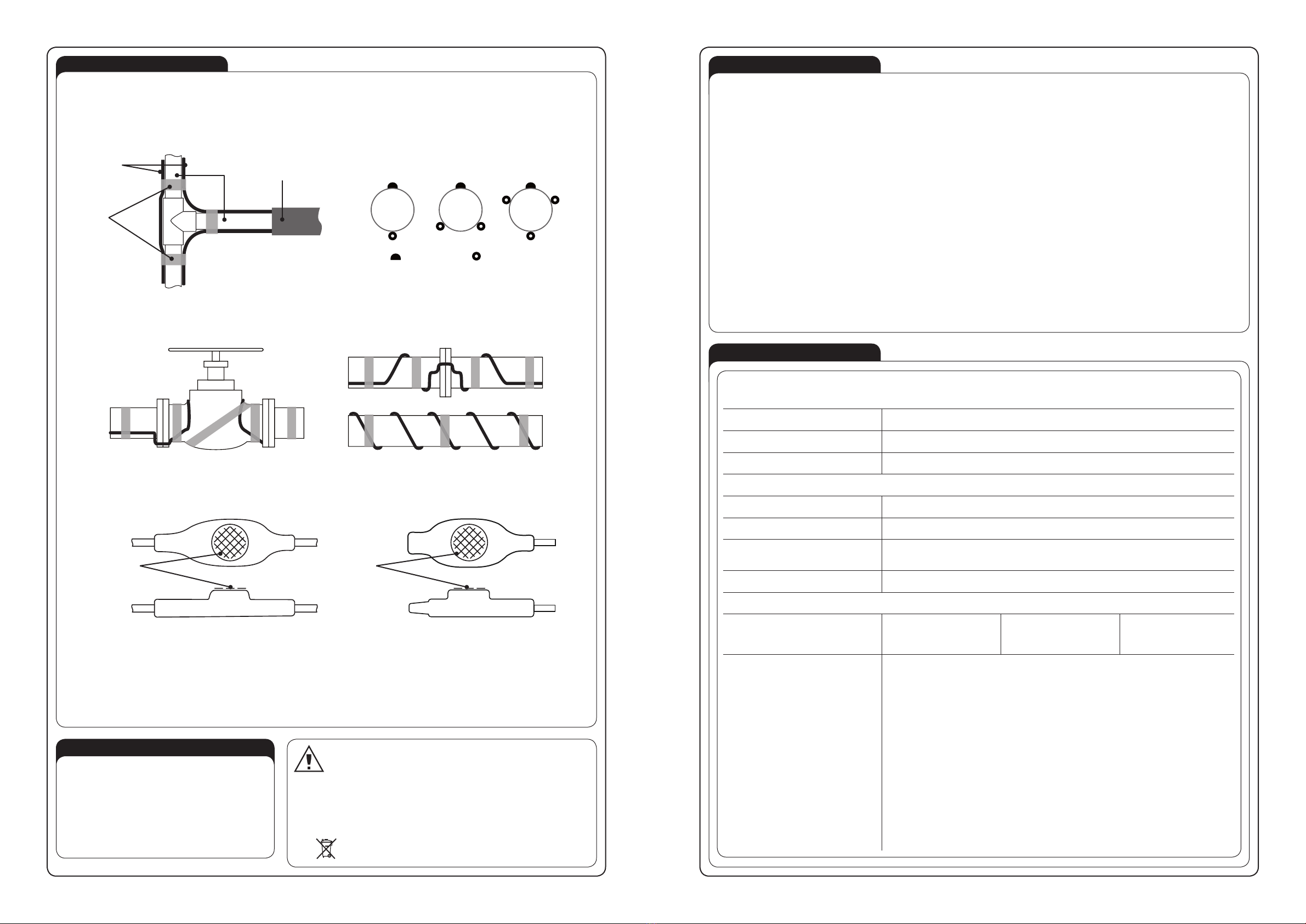
A DRAFT OR A PICTURE OF THE HEATING TABLE, SUPPLY TABLE AND ACCESSORIES
DESCRIPTION
GPRU type heating cables are used to protect against freezing. They are laid on the outer surface of
pipes and valves, the same, the emitted heat allows to protect the inner liquid against freezing. The
cable is equipped with a temperature regulator which automatically switches on the heating circuit at
+3°C (*+5°C) and switches off at a temperature of +11°C (*+13°C). The device measures the tem-
perature on the pipe’s surface. In order to give a proper temperature measurement and an appropriate
response of the heating cable, it is very important to mount properly the temperature regulator on a
pipe. The measuring surface of a temperature regulator should be maximally equal with the protected
surface of a pipe. Too little contact of both surfaces can cause a heat damage to the heating cable. The
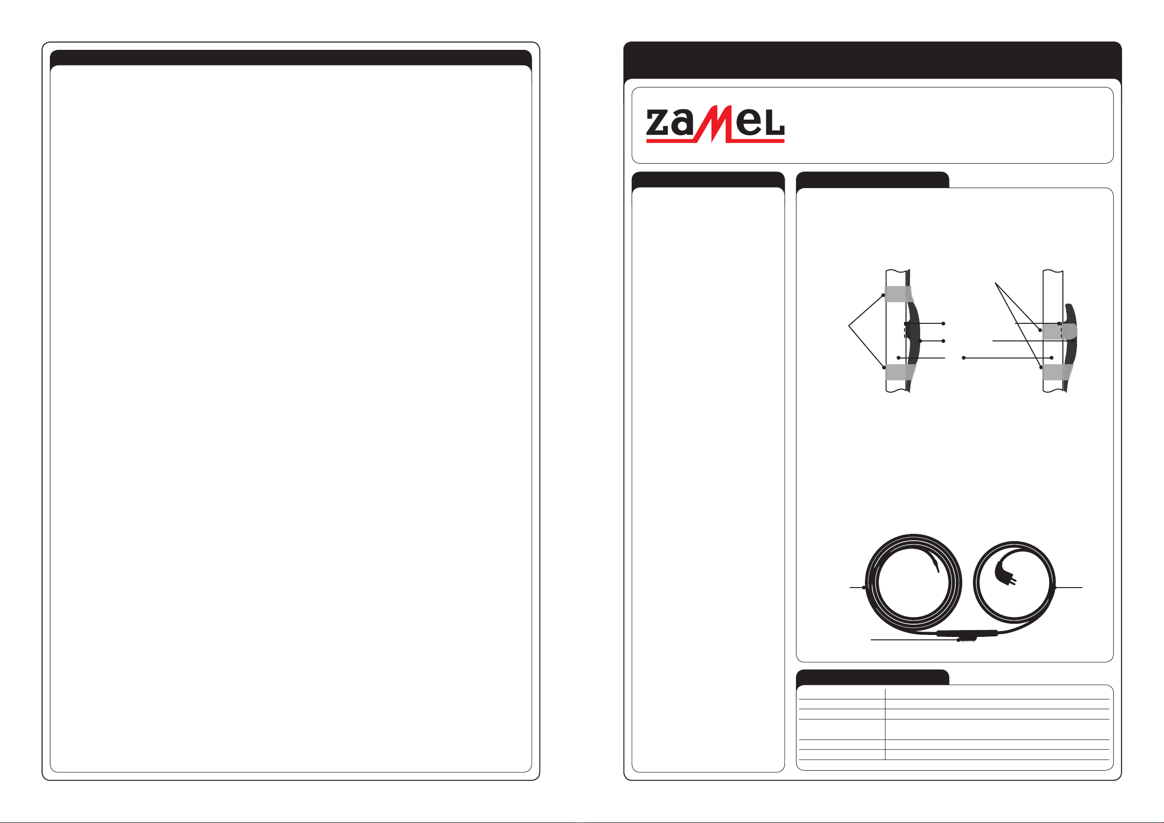
way of applying a temperature regulator to the surface of a pipe is shown in the drawing.
Fig. A way of placing a temperature regulator to the pipe’s surface
The heating cable should be mounted on the pipe by means of cable ties or mounting tapes. In addi-
tion, it is recommended to apply insulations, e.g. heat insulations. Insulation should be made of fl ame
retardant or noncombustible material.
The GPRU heating cables are designed for outdoor and indoor use. They are made for 230 V nominal
voltage 230 V and 18 W/m (*15 W/m).
The temperature regulator is placed on the connection of heating and power cables, acting as a me-
chanical connection of the heating and power part of a device.
The supply cable is ended with a plug that is inserted into a 230 V AC socket.
Heating cable GPRU - the set included:
● one-sided 18 W/m (*15 W/m) power supply heating cable connected by means of a temperature
regulator with w supply cable ended with a plug,
● installation instruction with the Warranty Card.
Fig. Heating cable with supply cable and a temperature regulator
REMARKS
• During installation it is required to follow in-
structions included in the Heating Cable Man-
ual Instruction
• It is forbidden to mount the cable on pins,
bolts, screws or other fi xing elements that can
damage the outer coating of cables.
• The installation of a temperature regulator,
which is a part of a complete hating cable,
should be carried out with a particular attention
so that the measuring surface of a tempera-
ture regulator is closely attached to the pipe.
• The cable installation base must be smooth
with no sharp edges or sharp fi xing elements
• Heating unit cannot be mounted on non-uni-
form bases.
• The heating cable should not be installed in
places with permanent building.
• The heating cable, the supply cable and the
plug resistance must be measured at least
twice: after opening the packaging and before
starting the installation works and after arrang-
ing the heating cable in its fi nal place.
• It is not advisable to install the heating mats if
the ambient temperature is below + 5°C.
• Don’t cut the heating cable or its connection
with power supply cable and the plug.
• The heating cable should not undergo exces-
sive strain and should be protected against
sharp device damage.
• It is required to make a draft or add pictures of
the arrangement of the heating cable, power
supply cable and the connection place of the
heating cable with power cable (“cold wire”).
The draft or pictures are an integral part of the
as-built documentation.
• Heating unit must be supplied by means of a
device from TN-S electric circuit with RCD (re-
sidual current device) of nominal power supply
lower than 30 mA. The installation should have
surge protection.
• The heating cables must not come into con-
tact, cross with each other or other cables
- this could damage the insulation. The mini-
mum distance between the heating cables
must not be less than 5 times its diameter.
• The heating cable must be evenly wrapped on
the protected surface.
• The non-detachable supply cable cannot be
replaced. If the cord is damaged, the equip-
ment is useless.
• The device is not intended to be used by peo-
ple (children) with limited physical, feeling or
psychic ability or people without experience
or without the device knowledge unless it is
under supervision of a person responsible for
safety or according to installation manual.
• Pay attention to children - they must not play
with the device.
• Do not instal on pipes with the temperature
higher than niż 80°C.
• The radius of heating cable bending shall not
be less than 8 times of its diameter.
• The heating cable cannot be immersed in any
liquid.
• The GPRU heating cable is not designed to
be used on roofs, in gutters, in drain pipes, on
pavements, stairs and driveways.
TECHNICAL DATA
Heating cable TYPE GPRU 2 ÷ 20,5 m long
Power supply voltage: 230 V AC / 50 Hz
Unit power: 18 W/m (* 15 W/m)
Operating temperature: Automatic thermostat with an operating range of +3÷+11 oC (*+5÷+13°C)
(tolerance +/-3 oC)
Supply type: one-sided
Heating cable: two-wire, shielded
The heating cable is ended with power supply cable at one side with a plug.
MATEC – ELECTRIC ANTIFREEZING SYSTEMS MANUAL INSTRUCTION
ANTIFREEZING HEATING CABLE TYPE GPRU FOR PIPE PROTECTION
For GPRU-2/15 the thermostat is on the end of the heating cable
* - for heating cable GPRU-2/15 (15W/m)
Heating cable Supply
cable
with plug
Temperature
regulator
(*)
Heating cable
with thermostat
Pipe
Mounting
tape
Mounting
tape
Fully contact thermostat

plik: inst_zamel_gb_GPRU | modyfi kacja: 07.06.2016 plik: inst_zamel_gb_GPRU | modyfi kacja: 07.06.2016
INSTALLATION
1. Before purchase, measure the pipe’s surface that should be protected against freezing.
2. Choose a heating cable depending on the surface, its arrangement and its function.
3. Unpack particular elements and inspect visually of what you have received.
4. Check the heating cable resistance with the supply cable and the plug based on the value given on the label. (The measurement equipment must be
certifi ed).
5. Make a draft based on the cable arrangement. A draft or pictures are an integral part of the as-built documentation.
6. Place the heating cable on the pipe and attach it by means of a reinforced tape at intervals of 25 cm. The advisable arrangement of a cable on the pipe
is longitudinal (along the pipe’s axis).
Fig. Longitudinal mounting of a temperature controller and a heating cable
Different ways of heating cable arrangement are shown below:
Fig. Ways of placing a able on a pipe
7. While mounting a thermostat, it is very important to mount it properly so that its fl at, protruding surface is accurately attached to the surface of a pipe.
Fig. Measurement surface of a thermostat (a temperature regulator)
8. After laying and fi xing the heating cable, it is necessary to check the outer layer of cables and device effi ciency by means of a resistance measurement.
9. Complete the WARRANTY CARD with a description of resistance measures.
10. Plugging the device into an 230 V AC electrical outlet with ground prong.
11. After checking the operation of the cable, put an insulation with earthing around a pipe and the cable placed on it.
The electrical installation, the GPRU heating cable and the supply cable plug is connected to, should be carried out in accordance
with standards valid in the country.
WARRANTY
WARRANTY CARD
ZAMEL Sp. z o.o. declares and assures that the electric heating systems MATEC (heating cables) manufactured and supplied by ZAMEL Sp. z o.o. are
compliant with current standards in the Company and binding norms in Poland. The warranty includes all MATEC products under the condition of proper
storage, transport, installation and operation according to binding norms. There is 2 year warranty for MATEC products and the warranty refers to defects
made by the manufacturer itself.
GENERAL WARRANTY CONDITIONS AND CLAIM CONSIDERATION BY ZAMEL Sp. z o.o.
1. ZAMEL Sp. z o.o. assures warranty for MATEC products. There is 2 year warranty for the heating cables. Warranty time starts at the moment of product
sell by ZAMEL Sp. z o.o. to the Purchaser. Be able to provide as a proof of purchase of the product an invoice by ZAMEL Sp. z o. o.
2. ZAMEL Sp. z o.o. shall process the claim at its own discretion.
3. The purchaser must inform about the claim which will be considered within 14 workdays only after proper claim notifi cation. The PURCHASER shall
lay any claims in writing to the Authorised Point or ZAMEL Sp. z o.o. only on presentation of an invoice (or its number and date of issue)
4. The properly fi lled Warranty Card should include a draft or a photo o installed heating and supply cable and a plug (with distances between heating
cable runs and neuralgic points e.g. close to a valve).
5. In case it appears that ZAMEL Sp. z o.o. is not the manufacturer of the claimed product or in case the claim is deemed void by ZAMEL Sp. z o.o., the
Purchaser will bear all the costs connected with claim consideration.
6. When your Warranty is invoked, your damaged product will be replaced free of charge to yourself by ZAMEL Sp. z o.o.
7. The manufacturer warranty is not valid in below cases::
• damage caused by unauthorised modifi cations made by the PURCHASER or any third parties to the product
• mechanical damage of the device
• wrong power supply
• electric installation which is not compliant with current IEE wiring regulations and installations
• damage caused by incorrect product mounting - not according with MATEC Installation Manual.
8. In case of product claim by an indirect Purchaser of ZAMEL products, the Purchaser is obliged to present the claim to the Supplier (where the product
was purchased).
ZAMEL Sp. z o.o.
Installation place
Post code, city/town
Street, Home/Flat No
Telephone
Filled by the electrician
Electrician Name/Surname
Telephone
Nr of a Certifi ed Electrician /
Expire date of a Certifi ed Electrician
Installation date
Resistance measurement results of the complete Heating Mat:
After the package was opened
(before installation) [Ω]:
After laying the heating cable
(before connecting plug to
electrical installation} [Ω]:
Signature / stamp Place for the Heating cable label
OPERATION
• The GPRU cable is permanently connected with a thermostat
which switches on and switches off the heating in the temper-
ature range of
+3÷+11°C (*+5÷+13°C)
(thermostat tolerance
+/-3°C) which causes the thermostat operates in the auto-
matic mode.
• During summer time it is advisable to switch off the heating
cable by disconnecting the plug from the electrical socket.
• Before the heating season starts (winter season) it is advis-
able to check the heating and supply cable surface, possible
insulation damages and the resistance. The aim of the above
is to eliminate a danger of damaged cable exploitation.
The device is designed for single-phase installation and must be installed
in accordance with standards valid in a particular country. The device should
be connected according to the details included in this operating manual. In-
stallation, connection and control should be carried out by a qualifi ed electri-
cian staff, who act in accordance with the service manual and the device
functions. Before installation make sure the connection cables are not under voltage.
Improper transport, storage, and use of the device infl uence its wrong functioning. It is
not advisable to install the device in the following cases: if any device part is missing
or the device is damaged or deformed. In case of improper functioning of the device
contact the producer.
The symbol means selective collecting of electrical and electronic equipment.
It is forbidden to put the used equipment together with other waste.
UWAGA
* - for heating cable GPRU-2/15 (15W/m)
Thermostat Heating cable
1. 2. 3.
Heating cable
Mounting
tape TMW-01
Pipes Lagging
(*)
Surface
temperature
measurement
by thermostat
Surface
temperature
measurement
by thermostat
Other Zamel Cables And Connectors manuals
Popular Cables And Connectors manuals by other brands

Burndy
Burndy Continental Industries thermOweld BR-1 instructions

Staubli
Staubli CombiTac MA213-07 Assembly instructions

Staubli
Staubli Multi-Contact ID/B16BV-NS-A Assembly instructions

Gleason Reel
Gleason Reel Spring Stack Electric Cable Reels Sho Twin Installation and maintenance instructions

Vega Absolute
Vega Absolute RP Series user manual

Russound
Russound SRM-2.1 instruction manual