ZCM-42 TIME PROGRAMMER
Wi-Fi-CONFIGURABLE USER’S MANUAL
ZAMEL Sp. z o.o.
ul. Zielona 27, 43-200 Pszczyna, Poland
tel. +48 32 210 46 65, fax +48 32 210 80 04
zcm-42_inst_ext_gb | 09.02.21
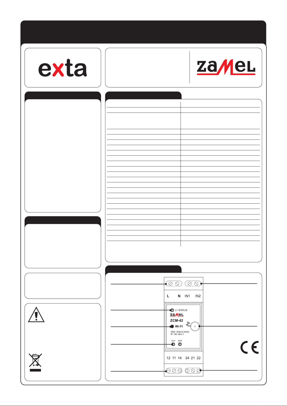
APPEARANCE
FEATURES
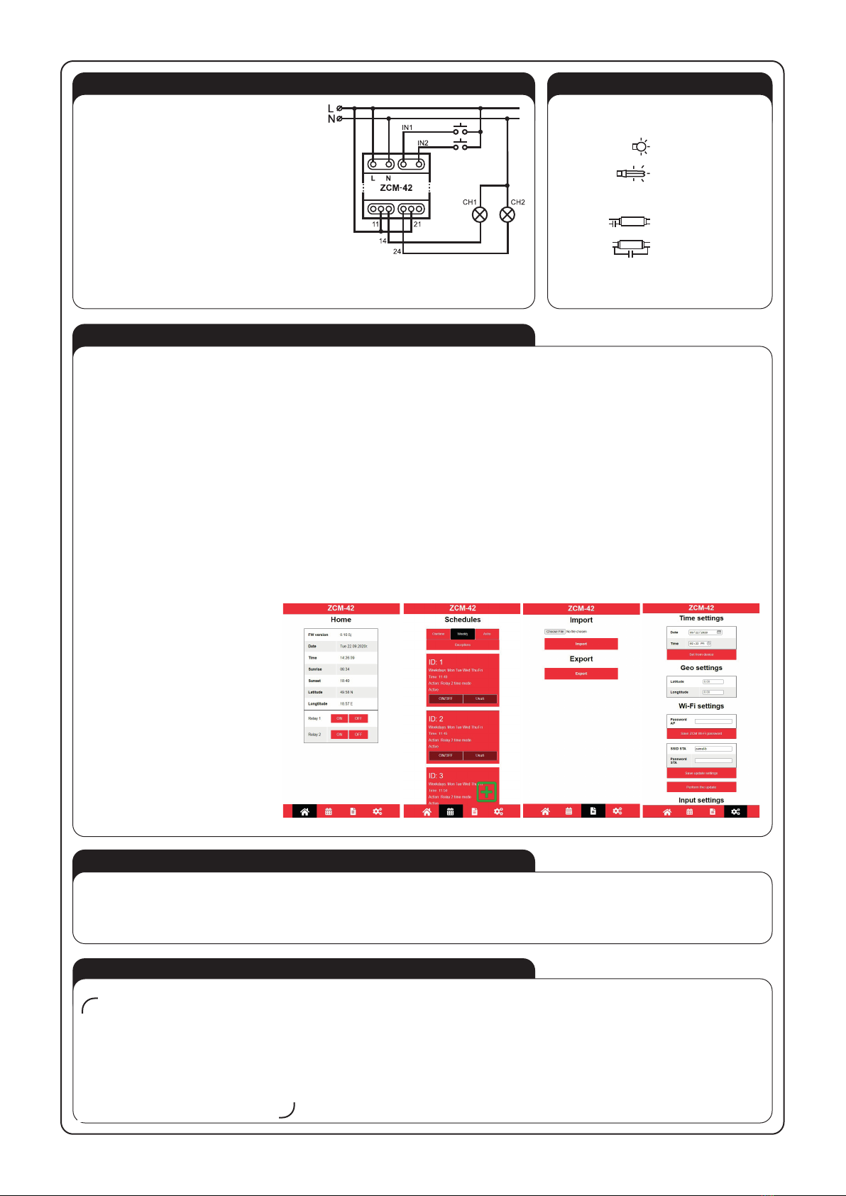
DESCRIPTION
• control based on sunrise and sunset times,
• option to change calculated sunrise and sun-
set times manually,
• control based on hour and day of the week,
• option to program one-time events and ex-
ceptions,
• setting parameters via a website thanks to the
Wi-Fi module,
• no need to install any applications,
• settings are kept without requiring a battery.
The ZCM-42 time programmer is used to per-
form time functions in automation and control
systems. It can control loads connected to out-
puts depending on the hour and day of the week
as well as sunrise and sunset times (including
information on geographical coordinates of the
place of time programmer installation, current
date, and time shift set). The programmer also
offers the possibility of setting one-time events
– executed on a given day of the year – and
makes it possible to define exceptions (time pe-
riods during which control is executed different-
ly than set in weekly and astro schedules). The
programmer allows you to program 80 events
for all types (weekly, astro, and one-time events
as well as exceptions), but the main advantage
of this programmer is that they are not simply
ON/OFF pairs but independent events, which
allows for very flexible control of the connected
devices – for example, you can turn on a device
using the astro function and turn it off using the
weekly function. Parameters are set via a web-
site thanks to the Wi-Fi module included with
the device. In addition, the programmer keeps
device settings without requiring a battery when
there is a power failure and offers the possibility
of importing/exporting saved schedules.
Hereby, ZAMEL Sp. z o. o. declares that the
radio equipment type ZCM-42 is in compliance
with Directive 2014/53/EU. The full text of the
EU declaration of conformity is available at the
following internet address: www.zamel.com
The device should be connected to a one-
phase network in accordance with legally
binding standards. The connection method
is described in this manual. Any activities
related to installation, connection, and ad-
justment should be performed by qualied
electricians who have read this user’s man-
ual and familiarised themselves with device
functions. Removing the enclosure voids the
warranty and poses a risk of electric shock. Before installation,
make sure that there is no voltage on connection cables. To
install the device, use a cross-head screwdriver with a diam-
eter of 3.5 mm. The proper operation of the device is affected
by how the device is transported, stored, and used. It is not
advisable to install the device in the following cases: lack of
any components, damage to or deformation of the device. If the
device operates improperly, please contact the manufacturer.
NOTE
TECHNICAL DATA
Nominal supply voltage: 230 V AC 50 / 60 Hz
Supply voltage tolerance: -15 ÷ +10 %
Nominal power consumption:
0.75 W - Wi-Fi disabled
0.85 W - Wi-Fi enabled
1.4 W - with one relay turned on
2 W - with two relays turned on
Transmission: Wi-Fi 2.4 GHz b/g/n
Operating range: 100 m in the open area*
Transmitting power: ERP < 20 mW
Supply voltage / Wi-Fi status signalling: LED (green)
Number of outputs: 2
Input state signalling: 2 LEDs (red)
Parameters of relay contacts: 2 x NO/NC 16 A / 250 V AC (inrush: 111 A / 20 ms)
Number of inputs: 2
Can be used with: monostable (returnable), bistable switches
Schedules: astro, weekly, yearly, exceptions
Number of events: 80 for all schedule types
Settings are kept by: supercapacitor - settings are kept for 24 hours
Operating temperature: -10 ÷ +55 °C
Operation position: any
Enclosure mounting: DIN-Rail
Enclosure IP rating: IP20
Number of connection terminals: 10
Cross-section of connection cables 0.2 ÷ 2.5 mm²
Overvoltage category: II
Contamination degree: 2
Dimensions: two-module enclosure 90x35x66 mm
Weight: 163 g
* The operating range given refers to an open area, i.e. ideal conditions, without obstacles. If there are obstacles between the transmitter
and the receiver, the operating range should be expected to be reduced by: 10-40% for bricks, 5-20% for wood and plaster, 40-80% for
reinforced concrete, 90-100% for metal, and 10-20% for glass. In addition, overhead and underground high-voltage power lines as well as
cell towers located near devices have a negative impact on the operating range.
Do not dispose of this device together with
other waste! To avoid harmful effects on the
environment and human health, the worn-out
device should be stored in designated areas.
Electrical waste from households may be handed
over to the waste collector established for this
purpose free of change and in any amount,
as well as to the store when purchasing new
equipment.
Output terminals 12, 11, 14
Supply terminals L, N Input terminals IN1, IN2
Antenna port
Output terminals 24, 21, 22
Power / Wi-Fi activity
signalling
Wi-Fi activation / deactivation
button
Input state signalling