H. ZANDER GmbH & Co. KG • Am Gut Wolf 15 • 52070 Aachen • Germany
Tel +49 (0)241 9105010 • Fax +49 (0)241 91050138 • info@zander-aachen.de • www.zander-aachen.de 1
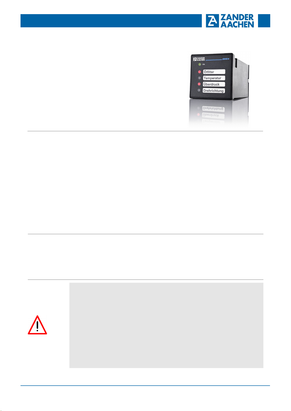
Fault Indicator System ENQ4
L05
E61-283-00
Operating Instructions English translation
Errors and technical changes reserved
Simplify maintenance
Report faults
Avoid damages
Reduce service costs
The ENQ4 offers a complete fault indicator unit for recording
unapproved operating conditions such as excessive pressure
or excessive temperature in a compact design. The devices are
successfully used with compressors, automatic production machi-
nes, vehicles, heating systems and air-conditioners.
The closing of the input S5 activates the opening of the
contact A1-14 without storage function. The contact will
close with the opening of S5 provided that an input S1-S4
do not have a fault report.
Additionally each input is equipped with a signal delay of
about 200 ms for the purpose of filtering out any possible
current interruptions occurring momentarily. Therefore the
switching on of the connected machine by A1-14 and the
simultanous closing of the contacts S1..S4 do not lead to a
fault report.
These measures permit the use of the equipment with un-
shielded input cables up to 100 m in length.
Safety
Precautions
against electrostatic discharge (ESD protection).
Opening the device, any manipulation of the device and
the avoidance of the safety facilities are not permitted.
All relevant safety regulations and standards must be
attended to.
Non-observance of the safety regulations may cause
death, severe injuries or substantial damage to property.
Before use, please, read the operating instructions and
keep it in a safe place. Make sure that the operating
instructions are always available for installation, initial
operation and maintenance.
The installation and operation must be carried out by
qualified personnel only,
who is familiar with the professional handling of machine
equipment,
who is familiar with the valid rules of industrial safety
and accident prevention,
who read and understood the operating instructions and
the system manual.
The safe function of the device during machine operation
cannot be guaranteed in case of wrong connection or
improper operation. This may lead to fatal injuries.
Pay attention to country specific regulations.
The electrical installation must be performed after dis-
connecting the device and the machine from the mains
supply.
The wiring must be carried out according to the instruc-
tions of this operating manual.
The person who programs the device must be protected
Non-observance of the instructions above will cause the
loss of warranty.
Correct Use
Features
Function During normal operation (all external contacts on the inputs
S1..S4 are closed) the internal contact A1-14 is closed.
The alarm contact A1-14 (NC) opens as soon as a fault
alarm input S1..S4 opens. The machine is switched off until
the fault is acknowledged.
Each input channel has a storage function so that faults
occurring even sporadically are recognised. The acknow-
ledgment takes place with the interruption of the power
supply of the ENQ4 system.
There are 4 fault-detection-inputs and one additionel test
input, which operates directly to the output contact of the
unit.
Each fault (input signal-contact open) will be indicated by a
red LED at the front panel, the fault free operation is shown
by a green LED. The report is made through NC-contacts
so that separate cable monitoring is assured.
Various operating/reporting voltages up to AC 230V are
available.
Special function test operation (input S5):
Installation ENQ4 is a panel-mounting device for 45 x 45 mm cutout.
It has a plastic front panel IP54 with identification panel for
the fault messages. A paperstrip for inscriptions is en-
closed at each item. This strip can easily be pushed into
the considered side pocket.
In addition to each fault report display, space for text for
customer specific formatting of the reports is provided. We
will supply the devices with the appropriate text as per your
text documentation for mass production requirements.
All electronic components are integrated in a panel-moun-
ting housing 48 x 48 mm. The front of the device is water
and dust proof. Several modules can be arranged next to
one another in the form of a tableau.
A plastic front frame with external dimensions of 55 x 55 mm
is available as an accessory.


