Zanotti GM1 Operation instructions

GM
MANUALE USO E MANUTENZIONE
USE AND MAINTENANCE INSTRUCTIONS
NOTICE DE MODE D’EMPLOI ET D’ENTRETIEN
GEBRAUCHS- UND WARTUNGSHANDBUCH
MANUAL DE USO Y MANUTENCIÓN
I
GB
F
D
E

18
CONTENTS
1. Safety recommendations
2
.
Table of warning and attention plates
3. Description of the unit
4. Operation
5. Handling
6. Installation
6.1 Plates
6.2 Dimensions
6.3 Location
6.4 Free room
6.5 Installation
6.6 Fitting the remote panel
6.7 Safety devices
6.8 Cleaning
7. Connecting the unit
7.1 Electric connection
7.2 Connection to water system
8. Electric controls
8.1 Control panel
9. Checks, regulations and adjustments
9.1 Starting
10. Wiring
11. Maintenance and repairs
12. Routine maintenance
12.1 Periodical maintenance
12.2 Service operations to be carried out by qualified technicians or by the manufacturer
12.3 Troubleshooting
12.4 Alarms
13. How to order spare parts
14. How to dispose of the packing
15. How to dispose of the unit

19
Thank you for choosing Uniblock.
Please read these instructions carefully. They provide details and advice on the correct method of installing,
using and maintaining this unit, in order to obtain maximum reliability, efficiency and long life.
1 SAFETY RECOMMENDATIONS
When installing and using the unit please follow the recommendations listed here below.
• Installation shall be carried out in strict compliance with the diagrams and instructions supplied by the
manufacturer.
• Damages due to improper connections are excluded.
• The electric system available where the unit is installed shall meet the relevant standards in force.
• Maintenance shall be effected by trained personnel or by the manufacturer according to the provisions
supplied by EN378.
WARNING
Use safety gloves to protect your hands from possible cuts.
The user is strongly recommended to contact the manufacturer before attempting any intervention
on the unit and any use not corresponding to the manufacturer’s indications (in particular as for the field of
application) and to enquire about the possible dangers and contra-indications connected with an improper use
of the machine.
• The unit shall be used following these instructions and sticking to the destination of use indicated by the
supplier. Any incorrect use can result in damages to the unit and represents a serious danger for people’s
health.
ATTENTION
The unit is not suitable for working in explosive environments.
Therefore the use of the unit in an explosion-dangerous atmosphere is absolutely
forbidden.
ATTENTION
The unit is not suitable for working in salty environments. In such a case protect
condenser and evaporator with appropriate means.
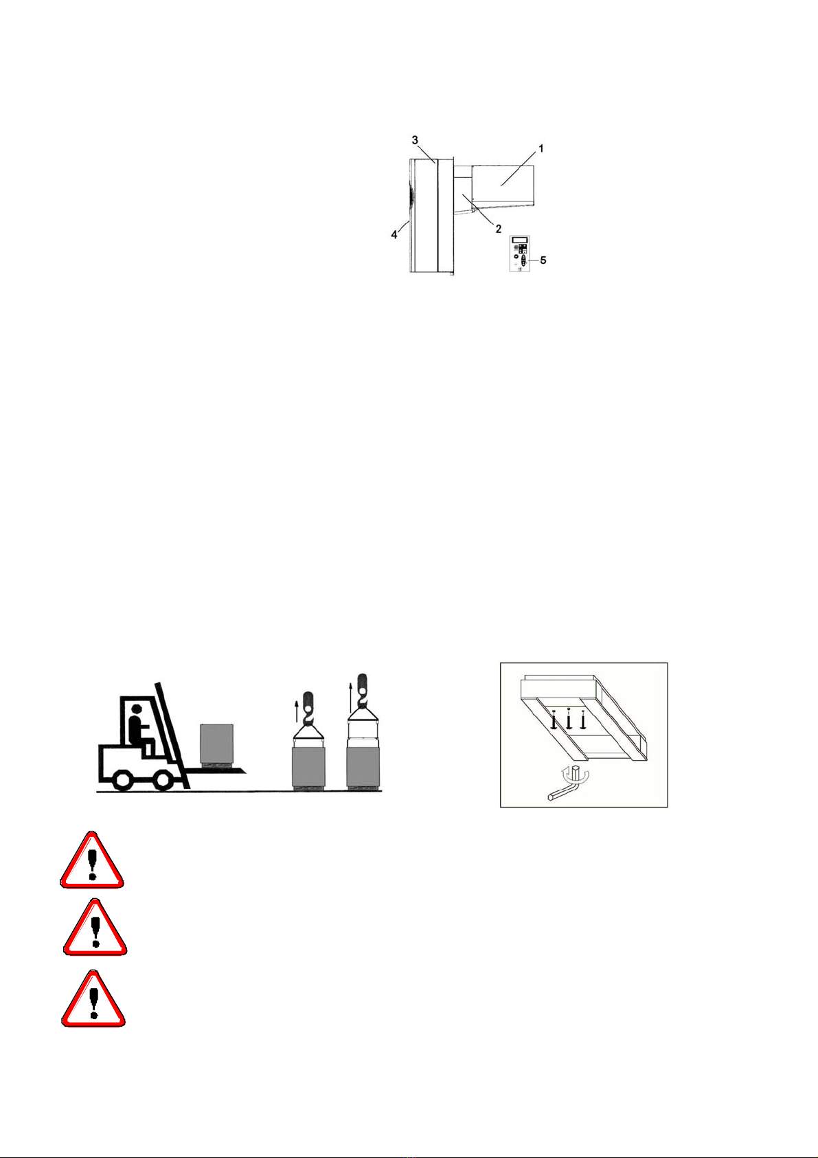
When maintenance involves operations on the refrigerating circuit, empty the system and let it reach the
atmospheric pressure.
WARNING
Do not discharge the refrigerant in the atmosphere. It must be recovered by
specialized technicians using suitable equipment.
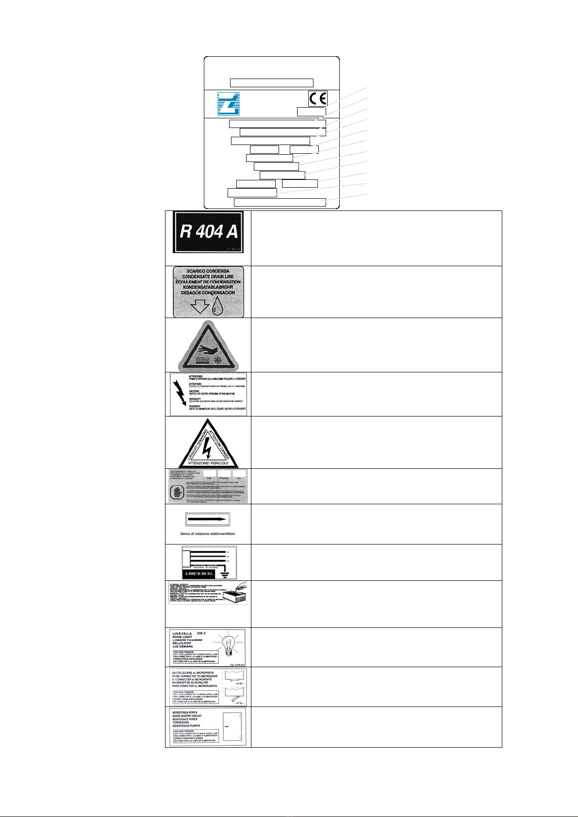
• Quantity and quality of the refrigerant to be charged are indicated on the data plate.
• Do not use refrigerants of different kind (especially inflammable fluids, for example hydrocarbons) or air.
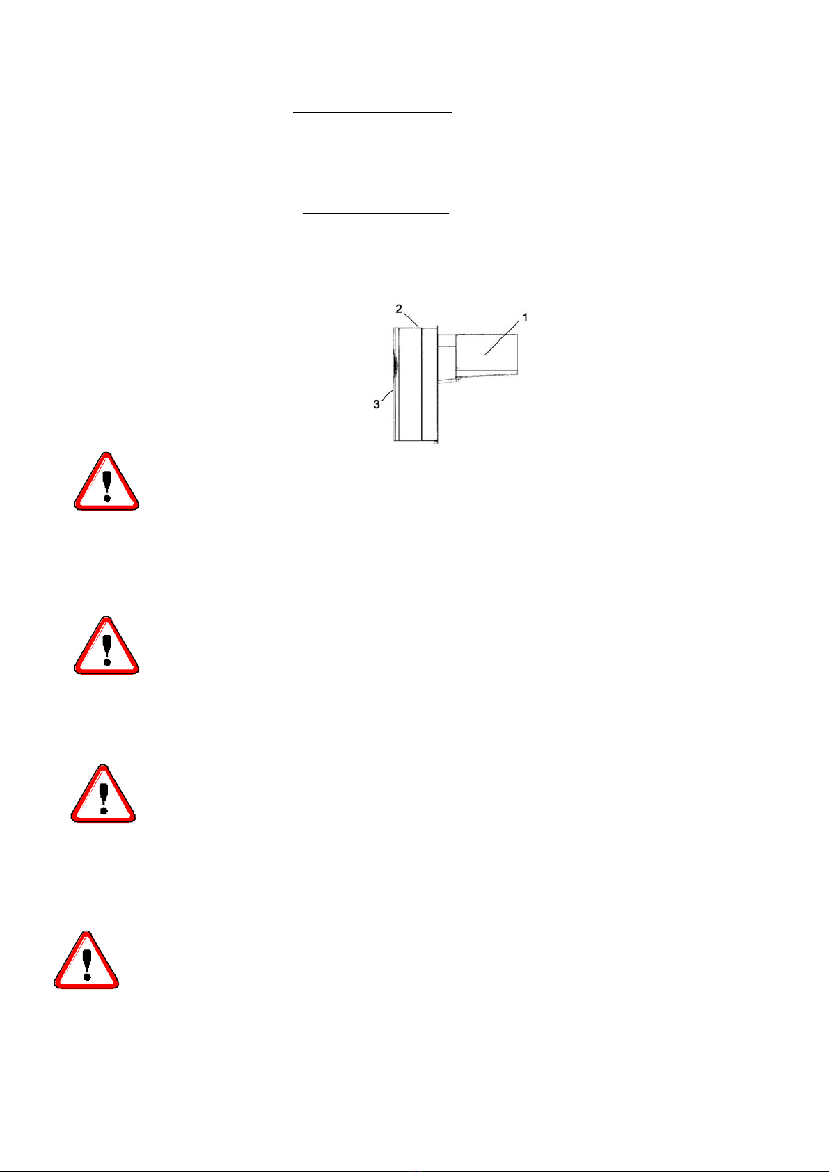
• Do not modify or alter the refrigerating circuit or its components (for example: welding on compressor
body)
• The final user shall protect the system from external fire dangers.

20
2 Table of warning and attention plates
Modello
Model
Matricola
Serial Number
Tensione
Voltage
Assorbimento Marcia
Run Absorption
Refrigerante
Refrigerant
Massa
Mass
V/Ph/Hz
AKw
Kg
Kg
Via Martin L. King, nr. 30
46020 PEGOGNAGA
(Mantova) - Italy
ZANOTTI S.p.A.
Modello
Model
Potenza nom.compressore
Nominal Horsepower
A
A
Assorbimento Max
Max Absorption
Assorbimento di spunto
Starting Absorption
Kw
Schema nr.
Diagram nr.
Refrigerant
Condensate drain line
Attention: hot or cold parts
Attention: switch off before operating on the unit.
Attention: danger of electrocution
Connect this cable to a circuit breaker, never to
the main line directly.
Direction of rotation
Colours of supply cable wires
Attention – important : clean the condenser
periodically by blowing air from the inside
outwards.
Stop the unit before cleaning.
Room light cable
Microdoor cable
Door heater cable
1) Year of manufacture
2) ZANOTTI unit code
3) Serial number
4) Voltage
5) Run Absorption
6) Max Absorption
7) Starting Absorption
8) Compressor’s nominal power
9) Refrigerant : Type; Quantity
10) Mass of the unit
11) Electric diagram number

21
3 Description of the unit
The GM series includes air-cooled or water-cooled (optional) condensing units
built on the basis of the single-block principle.
They consist of:
1. a condensing unit placed outside the cold room;
2. an insulating panel (optional) for wall-thru instead of straddle
installation;
3. an evaporator installed inside the room;
4. an electric control panel placed on the condensing unit;
5. a wall-mounted remote control panel (optional).
4 Operation
GM single blocks are compression units where cold is produced by vaporizing a
liquid refrigerant (HFC type) at low pressure in a heat exchanger (evaporator). The
resulting vapour is brought again into the liquid state by mechanical compression at a
higher pressure, followed by cooling in another heat exchanger (condenser).
The compressor is hermetic, with reciprocating motion, supplied with single-phase or
three-phase power.
Defrost takes place automatically in pre-set cycles, by injecting hot gas (standard) or
by means of heaters (optional); manual defrost is also possible.
5
Handling The unit can be handled by lifting and transport means.
UNSCREW THE FIXING SCREWS TO REMOVE CRATING FROM THE UNIT. (fig.
A).
WARNING
Make sure that no one is in transit in the operating area of the lifting/transport means
to prevent any possible accidents to people.
If the unit is in a wooden case or crate, sling the packing properly before handling
it.
Lifting speed shall be such as not to make the packed unit oscillate dangerously and
possibly fall.
Fig. A

22
6 Installation
6.1 Plates
The unit is supplied with warning and attention plates as listed in the relevant table.
6.2 Dimensions
A B C D E F G
GM1 735 790 264 280 510 368 400
GM2 830 790 264 280 510 585 620
GM3 830 982 364 350 632 585 620
6.3 Location
To obtain optimal operation of the unit act as follows:
A) Place the unit in a well ventilated room, far from heat sources.
B) Limit the number of door openings.
C) Make sure that the unit has good air supply and discharge.
D) Fit a drain line to the defrost water drain connection in the lower part of the unit.
Note: GM units are equipped with automatic evaporation of defrost water; drain is
just a precaution in case of troubles.
6.4 Free room
When installing the unit leave enough free room to allow opening, correct use and easy
maintenance in safe conditions.
Solution 1 Solution 3
Solution 2
Installation in a
coldroom with
more than one unit

23
A
Condensate drain line Ø 28
6.5 Installation
Straddle version:
before mounting the unit prepare the cuts and holes in the cold room wall shown in the picture.
Fix the unit in place with the appropriate screws. Position the unit on the cold room, connect the evaporator
drain tray spigot and the hole prepared in the cold room wall using the supplied fitting with pre-inserted
heater (for low temperature units only). Secure with the appropriate screw.
Fill the hole in the wall with insulating material, polyurethane or silicone, and mount the hole cover.
A
mm B
mm C
mm D
mm E
mm F
a°
GM1 19 316 288 83 43 6
GM2 19 316 503 83 43 6
GM3 19 425 503 83 43 6
Thru-wall version (optional):
A) Prepare a opening with suitable dimensions in the cold room wall (see picture).
B) Position the unit onto the cold room wall inserting the evaporator section in the opening.
C) Fix the unit using the screws supplied.
CE
D
G
Inject silicone all
around the panel
o
p
enin
g
Hole
Condensate drain line Ø 14
EEC
D
F
Fitting
B

24
Mod. A B C D E F G H
GM1 735 264 280 110 400 335 375 100
GM2 830 264 280 110 400 335 590 100
GM3 830 364 350 110 522 440 590 100
6.6 Fitting the remote panel (optional):
Fix the back plate to the wall using the pre-drilled holes; be careful the panel is kept
in a vertical position.
Fit the connecting cable between panel and unit making sure not to bundle it with
other cables.
ATTENTION
Maximum distance between panel and unit is 10 mt. For longer distances the special
“long distance module” should be used (optional).
ATTENTION
Check that the unit and its devices have suffered no damages
during transport. Pay special attention to the components
secured to the electric panel door and to the refrigerating circuit
pipes. Mount the unit as shown in the drawings; make sure that the
electric connections are carried out properly.

25
6.7 Safety devices
The following
mechanical safety devices
are supplied:
1. Fixed upper and side protections for evaporator and condensing unit, secured
by locking screws.
2. External fan protections placed on the evaporating and condensing units,
secured with screws.
The following
electrical safety devices
are supplied:
a. Protection of fans (belonging to motors) against high power absorption;
with automatic reset.
b. High pressure switch (only for special components) to protect against
excessive pressure; with automatic reset.
WARNING
Above devices have been developed to safeguard the operator’s safety.
6.8 Cleaning
Clean the unit carefully. Remove any dust, foreign substances and dirt possibly deposited during
handling. Use detergents and degreasers.
ATTENTION
Solvents are not allowed.
7 Connecting the unit
ATTENTION
Before connecting the unit make sure that mains voltage and frequency correspond
to the values shown in the data plate. Voltage tolerance: +/- 10% compared to
nominal value.
7.1 Electric connection
Connect the unit after checking the panel components.
ATTENTION
Connection to the electric line shall be effected applying a suitable safety device (a
circuit breaker or a ground fault interrupter) selected by the installer on the basis of the
line involved and of the absorption indicated on the unit plate.
If a cold room includes more units, each unit shall be provided with its own safety device.

26
Connect the unit paying attention to the colours of the supply cable wires:
a) 230V/1/50-60Hz Yellow/Green = Ground
Brown=Phase
b) 230V/3/50-60Hz 4 wires Blue = Phase
Yellow/Green = Ground
Brown = Phase
Black=Phase
c) 400/3/50 Hz 5 wires Blue = Neutral
Yellow/Green = Ground
Brown=Phase
Black=Phase
Black=Phase
We advise to install a microswitch (not supplied) on the cold room door which will
- switch on the light in the cold room, stop the unit and
- override the temperature alarm (for about one hour after door closing)
every time the door is opened.
The necessary cable is available with the unit. Connect it keeping in mind the following:
microswitch closed = door closed.
ATTENTION
Above microswitch is not supplied with the unit. If the microdoor cable is disconnected or
damaged, the same conditions will occur as in case of open door and connected microdoor.
“B” RANGE units (B = low temperature) are supplied with a cable for door heater connection, to
be made using a fuse suitable for the door heater used.
The unit is also equipped with a cable for cold room lamp connection (lamp voltage should be 230 V and lamp
max capacity 100 Watts).
ATTENTION
Do not connect microdoor, cold room light or door heater cables to the 230V line.
Each cable is equipped with a plate showing how it should be connected.
WARNING
Any defective electrical part should be replaced by trained personnel exclusively.
The electric connection should be effected by qualified personnel.
7.2 Connection to water system
(
water condenser
)
This connection is only necessary if the unit has a water-cooled condenser. It is
effected by following the indications of the tags positioned by the inlet and outlet
pipes. Connection pipes should never be smaller in diameter than those on the unit. A
minimum water pressure of 1 bar is required for correct operation of the unit.

27
8 Electric controls
8.1 Control panel
1. Control LED (GREEN)
ON : compressor is running, unit is refrigerating.
Flashing : compressor is in start delay mode.
OFF : compressor is off, room temperature is down to set value.
2. Control LED (GREEN)
ON : evaporator fan is running.
Flashing : evaporator fan is in start delay mode.
OFF : evaporator fan is off. Defrost is in course.
3. Control LED (YELLOW)
ON : Automatic or manual defrost is in course.
4. Alarm LED (RED)
ON : alarm has been activated because of a malfunctioning sensor, or pressure
switch intervention, or cold room temperature exceeding allowed tolerances.
OFF : Unit is operating normally.
5. DISPLAY : on connection to the mains it shows OFF to indicate the condition of
the unit. By pressing ON/OFF key for 3 seconds the unit is turned ON and the
display shows the cold room temperature. In programming mode the
parameters to be set are displayed; in alarm mode the alarm code is displayed.
6. "SET" key : when pressed for 3 seconds it lights up and allows room
temperature to be set. During programming it is used to pass from a submenu
to an upper one.
7. "DOWN/ROOM LIGHT" key: in programming mode or when setting room
temperature it is used to reduce the value displayed; otherwise it is used to
switch on/off the cold room light.
8. "SB.M./UP" key: in programming mode it is used to increase the values
displayed. If pressed for more than 4 seconds it enables manual defrost to be
carried out.

28
9. "ON/OFF" key: when pressed for 3 seconds it turns the unit on or off.
10. "Enter" key: it gives access to programming menu and submenus. Access
to the programming mode requires the installator’s assistance and should
be effected only if necessary.
9 Checks, regulations and adjustments
Before turning the unit on, check that:
- locking screws are tight
- electrical connections have been carried out correctly.
In the event that the unit has been opened:
- no tools were left inside
- assembly is correct
- there are no gas leaks
- front cover is secured correctly
9.1 Starting
Before starting the unit act as follows:
- Connect the unit to the mains. The display is turned on and shows OFF.
- If the unit has a preheating cycle, leave it in this condition for at least 3 hours.
- If the unit has a voltage monitor, leave it in this condition for at least 7 minutes to
have the counting phase carried out
- Set the required cold room temperature.
- Press ON/OFF key to switch the unit on.
ATTENTION
Medium temperature range : +10 -5°C
Low temperature range : -15 -25°C
Setting room temperature:
• Connect the unit to the mains. OFF is displayed.
• Press SET for three seconds. The green led lights up and the previously set
temperature is displayed.
• To change this value press following keys:
• UP to increase temperature
• DOWN to decrease temperature
Press SET key or wait 5 seconds to have room temperature displayed.
ATTENTION
24 hours after starting check evaporator state. If ice has formed, defrost frequency
should be increased. In low temperature units the evaporator condition should be
checked every week during the first month of operation.

29
10. Wiring
A wiring diagram, specific for the units of the GM series, is enclosed with these use
and maintenance instructions.
11. Maintenance and repairs
Suitable maintenance is crucial for obtaining longer life, perfect working conditions and high
efficiency of the unit as well as for ensuring the safety features provided by the
manufacturer.
12 Routine maintenance
Good operation of the unit requires the condenser to be cleaned periodically (frequency of
cleaning depends on the environment where the unit is installed).
Turn off the unit and clean it by blowing air from the inside outwards. Should no air jet be
available, use a long-haired brush and work on the outside of the condenser.
In case of water-cooled condensers have the unit cleaned by a plumber with special
descaling agents.
WARNING
Use safety gloves to protect your hands from possible cuts.
WARNING
Disconnect the unit before working on it.
10.1 Periodical maintenance
Periodically check wear condition of electrical contacts and remote switches; if necessary
replace them.
12.2 Service operations to be carried out by qualified technicians or by the manufacturer
Following operations shall be carried out by qualified technicians or by the manufacturer
exclusively. Under no circumstances the user is allowed to:
• replace electrical components
• work on the electric equipment
• repair mechanical parts
• work on the refrigerating system
• work on the control panel, ON/OFF and emergency switches
• work on protection and safety devices.
12.3 Troubleshooting
During operation following troubles may occur:
1 Compressor stops. The unit is equipped with an overtemperature device which stops the
compressor every time the max. allowable temperature of motor windings is exceeded.
Possible causes are:
- insufficient ventilation of the room where the unit is installed;
- anomaly in mains voltage;
- faulty operation of condenser fan.
Device reset is automatic.

30
2 Ice forms on the evaporator preventing air from flowing regularly.
Possible causes are:
- the door is opened too frequently;
- faulty operation of evaporator fan;
- faulty solenoid valve (in models with hot gas defrost);
- faulty defrost heater (in models with electric defrost);
- faulty defrost process. In this case some measures can be taken:
increase defrost termination temperature by some degrees, increase number of
defrosts.
ATTENTION
Do not use either hot water or any pointed, cutting, metal objects to remove ice blocks.
3. Display does not light up. Check:
- if there is power to the unit;
- if mains cable is connected properly;
- fuses inside the electric panel
4. Unit does not start operating when pressing ON/OFF key (the display is turned on):
check microdoor connection keeping in mind that the switch contact must be closed when
the door is closed.
Unsatisfactory efficiency of the unit:
If no defects are found in the unit check that: cold room doors are perfectly tight; there is no
cold dispersion; the cold room is used wisely; no unfrozen liquids or foodstuffs are placed in
the low temperature room; the evaporator is ice-free.
We recommend installation of the machines far from the doors especially when the cold room
is expected to be opened many times a day.
WARNING:
Removal of protections during machine operation is absolutely forbidden. They have
been developed to safeguard the operator’s safety.
12.4 Alarms
When an alarm condition occurs the following warning devices are activated (depending on
the nature of the alarm):
alarm led
buzzer
alarm relay.
The buzzer and the alarm relay can be muted by pressing any key. When a key is pressed,
the led flashes as long as the alarm condition is present. To have the alarm code
displayed, press ENTER key for 3 seconds: FnC appears. Press SB.M./UP key until AL is
displayed and then press ENTER. At this point a code is displayed indicating the cause of the
alarm.
To leave the alarm menu wait 15 seconds or press SET as long as cold room temperature is
displayed.

31
ALARM DISPLAY CAUSE REMEDY
High temperature (HI)
Red led and alarm relay
are activated; HI is
displayed in the alarm
menu as indicated above.
Excessive door openings
Excessive product load
Product too warm
Malfunction of the unit
Low temperature
(LI)
Red led, buzzer and alarm
relay are activated; LI is
displayed in the alarm
menu.
Malfunction of the
electronic controller Service intervention
Room sensor (E1)
Red led, buzzer and alarm
relay are activated; E1 and
Err are displayed
alternately.
Faulty sensor
Sensor with wrong
connection
Replace sensor
Evaporator sensor (E2)
Red led, buzzer and alarm
relay are activated; Err and
cold room temperature are
displayed alternately. E2 is
displayed in the alarm
menu.
Faulty sensor
Sensor with wrong
connection
Replace sensor
ondenser sensor
(E4)
Red led, buzzer and alarm
relay are activated; Err and
cold room temperature are
displayed alternately. E4 is
displayed in the alarm
menu.
Faulty sensor
Sensor with wrong
connection
Replace sensor
Condenser temperature
If the condensing
temperature exceeds a
factory pre-set value, red
led and buzzer are
activated; H4 is displayed
in the alarm menu.
Dirty condenser Clean condenser
High pressure
(E0)
Each time the pressure
switch trips, the buzzer and
the red led are activated. If
more than 10 trips occur in
1 hour, then the unit is
turned off automatically.
The alarm relay is
activated, Err and cold
room temperature are
displayed alternately. E0 is
displayed in the alarm
menu. To reset the unit
turn it off and then on
again using the ON/OFF
key.
Faulty operation of
condenser fan.
Dirty condenser.
Switch off the refrigerating
unit, wait a few seconds
and switch on again.

32
Voltage monitor (E8)
The voltage monitor is an
electronic device which
checks the supply voltage
of the unit. When voltage
variations exceed +/- 12%
the device activates the red
led, the buzzer and the
alarm led. Err and cold
room temperature are
displayed alternately. E8
is displayed in the alarm
menu. The unit stops for
about 6 minutes and
restarts automatically if
voltage is within the
prescribed limits.
Warning: On first starting
the monitor carries out a
counting phase of 7
minutes, during which the
unit should be left
connected but in OFF
condition.
Wrong supply voltage
13 HOW TO ORDER SPARE PARTS
When ordering spare parts make reference to the number written on the unit plate.
WARNING
Worn parts should be replaced only by qualified personnel or by the manufacturer.
14 HOW TO DISPOSE OF THE PACKING
Wooden, plastic, polystyrene packing shall be disposed of according to the regulations in force in the
country where the unit is used.
15 HOW TO DISPOSE OF THE UNIT
Do not discharge scrapped components in the environment. They should be disposed of by companies
dealing with special waste collection and recovery, according to the regulations in
force in the country where the unit is used.
WARNING
Do not discharge the refrigerant in the atmosphere. It should be disposed of by
companies dealing with special waste collection and recovery.

80
Zanotti S.p.A.
Via M.L. King, 30 - 46020 Pegognaga (MN) Italy
Tel. 0376.5551 - Fax 0376.536554
0MAN106/E
04/2004

1
LEGENDA SCHEMA ELETTRICO - WIRING DIAGRAM
LEGENDE SCHEMA ELECTRIQUE - SCHALTPLANLEGENDA
LEYENDA ESQUEMA ELECTRICO - LEGENDA ESQUEMA ELECTRICO
BA
SONDA TEMPERATURA AMBIENTE
ROOM SENSOR
SONDE CHAMBRE FROIDE
RAUMSONDE
SONDA CAMARA
SONDA TEMPERATURA AMBIENTE
BC
SONDA CONDENSATORE
CONDENSER ALARM SENSOR
SONDE ALARME CONDENSEUR
KOND-LÜFTER- ALARMSONDE
SONDA ALARMA CONDENSADOR
SONDA ALARME CONDENSADOR
BS
SONDA SBRINAMENTO
DEFROST SENSOR
SONDE DEGIVRAGE
ABTAUUNGSONDE
SONDA DESCARCHE
SONDA DEGELO
BVR
VARIATORE DI VELOCITA’
SPEED REGULATOR
VARIANT VITESSE
GESCHWINDIG- KEITSREGLER
VARIADOR DE VELOCIDAD
VARIADOR DE VELOCIDADE
BVRS
SONDA VARIATORE VELOCITA’
SPEED REGULATOR SENSOR
SONDE VARIATEUR VITESSE
GESCHWINDIGKEITSREGLERSONDE
SONDA VARIADOR VELOCIDAD
SONDA VARIADOR DE VELOCIDADE
E
RESISTENZE SBRINAMENTO
DEFROST HEATER
RESISTANCES DEGIVRAGE
ABTAUHEIZUNGEN
RESISTENCIAS DESCARCHE
RESISTêNCIAS DE DEGELO
E1
RESISTENZA CARTER COMPRESSORE M1
COMPRESSOR CRANKCASE HEATER
RESISTANCE CARTER COMPRESSEUR
KOMP.-ÖLSUMPFHEIZUNG
RESISTENCIA DEL CARTER DEL
COMPRESOR
RESISTêNCIA DO CARTER COMPRESSOR M1
EP
RESISTENZA PORTA
DOOR HEATER CIRCUIT
RESISTANCE PORTE
TÜRHEIZUNG
RESISTENCIA PUERTA
RESISTêNCIA DA PORTA
ER1
RISCALDATORE QUADRO
CONTROL BOARD HEATER
RESISTANCE TABLEAU CONTROLE
SCHALTTAFELHEIZUNG
RESISTENCIA CUADRO ELECTRICO
AQUECIMENTO DO QUADRO
ER2
RISCALDATORE MONITOR
VOLTAGE REGULATOR HEATER
RESISTANCE MONITEUR
MONITORHEIZUNG
RESISTENCIA MONITOR
AQUECIMENTO DO MONITOR
ES
RESISTENZA SCARICO CONDENSA
CONDENSATE DRAIN HEATER
RESISTANCE ECOULEMENT CONDENSE
KONDENSWASSERABLAUFHEIZUNG
RESISTENCIA DESAGÜE CONDENSACION
RESISTêNCIA DO DRENO DE CONDENSAÇãO
F13
FUSIBILE MONITOR
VOLTAGE REGULATOR FUSE
FUSIBLE MONITOR
MONITORSICHERUNG
FUSIBLE MONITOR
FUSíVEIS DO MONITOR

2
F1
FUSIBILE COMPRESSORE
COMPRESSOR FUSE
FUSIBLE COMPRESSEUR
KOMPRESSORSICHERUNG
FUSIBLE COMPRESOR
FUSIVEIS COMPRESSOR
F1E
CENTRALINA ELETTRONICA
ELECTRONIC CONTROL CAB
PANNEAU DE CONTRôLE ELECTRONIQUE
ELEKTRONENKONTROLL- PANEEL
PANEL DE CONTROL ELECTRONICO
F20
FUSIBILE AUSILIARIO
AUXILIARY FUSE
FUSIBLE AUXILIAIRE
HILFSICHERUNG
FUSIBLE AUXILIAR
FUSíVEIS AUXILIARES
FL
FUSIBILE LUCE CELLA
ROOM LIGHT FUSE
FUSIBLE LUMIERE CHAMBRE
ZELLELICHTSICHERUNG
FUSIBLE LUZ CAMARA
FUSíVEL LUZ DA CAMARA
FM
MONITOR
VOLTAGE REGULATOR
MONITOR
MONITOR
MONITOR
MONITOR
FTE
TERMOSTATO EMERGENZA
EMERGENCY ‘STAT
THERMOSTAT EMERGENCE
NOTSTANDE- THERMOSTAT
TERMOSTATO DE EMERGENCIA
TERMOSTATO EMERGêNCIA
H22
LAMPADA LUCE CELLA
COLDROOM LIGHT
LAMPELUMIERE CHAMBRE
KÜHLZELLELICHT
PILOTO LUZ CAMARA
LAMPADA LUZ DA CAMARAU
HA
ALLARME
ALARM
ALARME
ALARM
ALARMA
ALARME
HI
SUONERIA ALLARME TEMPERATURA
ACUSTIC TEMPERATURE ALARM
SONNERIE ALARME TEMPERATURE
TEMP.- ALARMWECKER
ALARMA SONORA DE TEMPERATURA
SINALEIRA ALARME DE TEMPERATURA
K1
TELERUTTORE COMPRESSORE M1
COMPRESSOR M 1 CONTACTOR
TELERUPTEUR COMPRESSEUR M 1
KOMPRESSORFERNSCHALTER M 1
CONTACTOR COMPRESOR M 1
INTERRUPTOR COMPRESSOR M1
K11
TELERUTTORE SBRINAMENTO
DEFROST CONTACTOR
TELERUPTEUR DEGIVRAGE
ABTAUFERNSCHALTER
CONTACTOR DESCARCHE
INTERRUPTOR DE DEGELO
M1
MOTORE COMPRESSORE nº1
COMPRESSOR MOTOR Nr.1
MOTEUR COMPRESSEUR Nr.1
KOMPRESSORMOTOR Nr.1
MOTOR COMPRESOR Nº1
MOTOR COMPRESSOR nº1
MP
MICRO PORTA CELLA
DOOR MICROSWITCH(ROOM)
MICROPORTE CHAMBRE
TÜRMIKROSCHALTER(KÜHLZELLE)
MICROPUERTA(CAMARA)
MICRO PORTA CAMARA
MVC
MOTORE VENTOLA CONDENSATORE
CONDENSER FAN MOTOR

3
MOTEUR VENTILATEUR CONDENSEUR
KOND.-VENTILATORMOTOR
MOTOR VENTILADOR CONDENSADOR
MVE
MOTORE VENTOLA EVAPORATORE
EVAPORATOR FAN MOTOR
MOTEUR VENTILATEUR EVAPORATEUR
VERDMF.-VENTILATORMOTOR
MOTOR VENTILADOR EVAPORADOR
P1MX
PRESSOSTATO INSERZIONE VENTOLA
COND.
COND. FAN STARTING PRESSURE SWITCH
PRESSOSTAT MISE EN MARCHE
VENTILATEUR COND.
KOND.-VENTILATORANLAUFPRESSOSTAT
PRESOSTATO INSERCION VENTILADOR
COND.
PRESSOSTATO ACIONADOR VENTILADOR
COND.
PMI
PRESSOSTATO BASSA PRESSIONE
L/P SWITCH
PRESSOSTAT BASSE PRESSION
NIEDERDRUCKPRESSOSTAT
PRESOSTATO BAJA PRESION
PRESSOSTATO BAIXA PRESSãO
PMX
PRESSOSTATO ALTA PRESSIONE
H/P SWITCH
PRESSOSTAT HAUTE PRESSION
HOCHDRUCKPRESSOSTAT
PRESOSTATO ALTA PRESION
PRESSOSTATO ALTA PRESSãO
Q1
INTERRUTTORE GENERALE
MAIN SWITCH
INTERRUPTEUR GENERAL
HAUPTSCHALTER
INTERRUPTOR GENERAL
INTERRUPTOR GENERAL
Q3
INTERRUTTORE ESCLUSIONE VAR.
VELOCITA’
COND. FAN SPEED REGULATOR “OFF”
SWITCH
INTERR. EXCLUSION VARIATEUR VITESSE
VENT. COND.
KOND.-VENTILATORGESCHW. REGLER
“AUS”
INTERR. EXCLUSION VARIADOR VELOCIDAD
VENT. COND.
INTERRUPTOR DESLIGA VAR. VELOCIDADE
T
TRASFORMATORE
TRANSFORMER
TRANSFORMATEUR
TRANSFORMATOR
TRANSFORMADOR
TRASFORMADOR
X
MORSETTIERA-CONNETTORE
TERMINAL BOARD-CONNECTOR
PLAQUE DE JONCTION-CONNECTEUR
KLEMMKASTEN-VERBINDER
REGLETA-CONECTOR
TERMINAL-CONECTOR
YG
SOLENOIDE GAS
REFRIGERANT SOLENOID
SOLENOIDE REFRIGERANT
KÄLTEMITTELMAGNETVENTIL
SOLENOIDE GAS
SOLENóIDE GáS
YS
SOLENOIDE GAS CALDO SBRINAMENTO
HOT GAS SOLENOID
SOLENOIDE GAZ CHAUD
HEISSGASSOLENOID
SOLENOIDE GAS CALIENTE
SOLENóIDE GáS QUENTE DEGELO
Other manuals for GM1
1
This manual suits for next models
2
Table of contents
Other Zanotti Refrigerator manuals
Popular Refrigerator manuals by other brands

Avanti
Avanti FFFD150H3S instruction manual

Emerson
Emerson Copeland OME-4MTL-12X Application guidelines

Lynx
Lynx L24BF User's manual & installation instructions

Hussmann
Hussmann Innovator Installation and service manual

Hotpoint
Hotpoint CSX20 How to get the best

True
True RESIDENTIAL ADA HEIGHT TURADA-24-R/L-RS-A-S Installation guide and user's manual