zarges A555000CE User manual

WARNING: ALL USERS OF THIS EQUIPMENT MUST READ AND
UNDERSTAND ALL INSTRUCTIONS. FAILURE TO DO SO MAY
RESULT IN SERIOUS INJURY OR DEATH. USERS SHOULD BE
FAMILIAR WITH PERTINENT REGULATIONS GOVERNING THIS
EQUIPMENT. ALL USERS OF THIS PRODUCT MUST BE PROPERLY
INSTRUCTED ON HOW TO USE THE DEVICE. AVOID CONTACT
WITH PHYSICAL HAZARDS (THERMAL, CHEMICAL, ELECTRICAL,
ETC.). MAKE ONLY COMPATIBLE CONNECTIONS.
Patent US # 8,312,966 / US # 8,646,575 / US 8,973,705 B2
BANTAM BEAMER
ADJUSTABLE FROM 3.5 -14 inches
Model # A555000CE

User Instructions must always be available to the user and are not to be removed except by the user of this equipment. For proper use, see supervisor,
User Instructions, or contact the manufacturer. Werner Co. can supply additional information upon request.
Compliant fall arrest and emergency rescue systems help prevent serious injury during fall arrest. Users and purchasers of this equipment must read
and understand the User Instructions provided for correct use and care of this product. All users of this equipment must understand the instructions,
operation, limitations and consequences of improper use of this equipment and be properly trained prior to use in accordance with applicable
standards. All references to “applicable standards” refer to EN, ANSI, OSHA, state, local, and/or federal standards that apply to approved use. The local
competent person must keep these instructions, make them available to users, and require their use.
Misuse or failure to follow warnings and instructions may result in serious personal injury or death.
PURPOSE
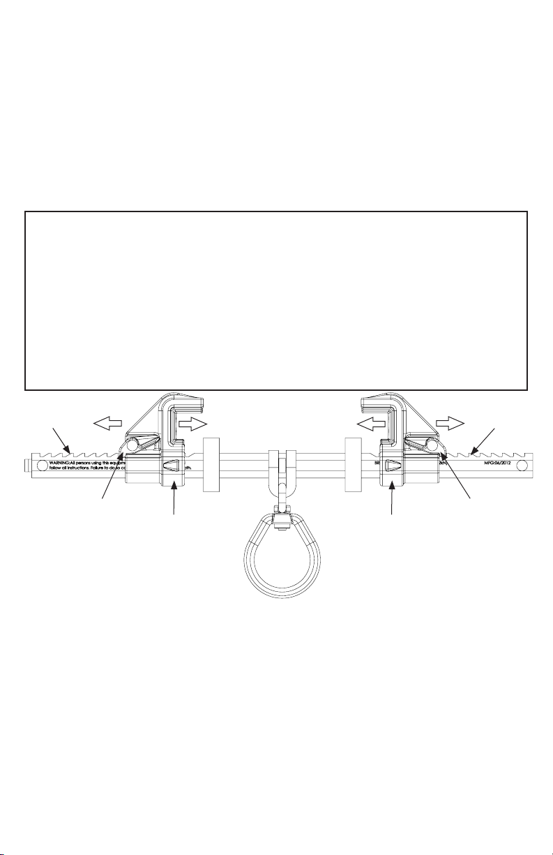
The A555000 is an anchorage connector designed to function as an interface between the anchorage and a fall arrest, work
positioning, rope access, or rescue system for the purpose of coupling the system to the anchorage. Any references to“anchorage
connector” in this manual include, and apply to, the A555000.
USE INSTRUCTIONS
1. A user must be of sound mind and body to properly and safely use this equipment in normal and emergency situations.
2. Before using a personal fall arrest system, user must be trained in accordance with the requirements of applicable standards
in the safe use of the system and its components.
3. Only use with systems that comply with applicable standards. The anchorage must have the strength capable of supporting
a static load, applied in the directions permitted by the system, of at least 5,000-lbf (22kN) in the absence of certication.
4. The user shall be equipped with a means of limiting the maximum dynamic forces exerted on the user during the arrest of a
fall to a maximum of 8 kN (1800-lbf). In the EU these forces must be limited to 6kN (1350-lbf).
5. Use of this product must be approved by an engineer or other qualied person (as dened by OSHA 29 CFR 1926.32 (m) and
EN 795:2012 Annex 1) to be compatible with any and all structural & operational characteristics of the selected installation
location and system to be connected to this anchorage connector.
6. The anchorage connector must be inspected prior to each use for wear, damage, and other deterioration. If defective
components are found the anchorage connector must be immediately removed from service in accordance with applicable
standards and the manufacturer’s inspection requirements.
7. The anchorage connector should be positioned in such a way that minimizes the potential for falls and the potential fall
distance during use. The complete fall arrest system must be planned (including all components, calculating fall clearance,
and swing fall) before using.
8. A rescue plan, and the means at hand to implement it, must be in place that provides the prompt rescue of users in the
event of a fall, or assures that users are able to rescue themselves.
9. After a fall occurs the anchorage connector must be removed from service and destroyed immediately.
10. The applicable essential health and safety requirements from EU Regulations have been checked and tests carried out to
verify the conformity of this PPE are available upon request.
11. Digital copy of this instructions can be found at at: https://www.wernerco.com/us/products/fall-protection/anchorage-
connectors/A5500Series/A555000.
USE LIMITATIONS: This anchorage connector has been tested in compliance with the requirements of ANSI/ASSE Z359.7 and
EN 795:2012 Type B. Compliance testing covers only the hardware and does not extend to the anchorage and substrate to which
the anchorage connector is attached. The anchorage connector must not be used outside its limitations, or for any purpose other
than that for which it is intended. If this anchorage connector is used dierently from these instructions, it must be designed,
installed, and used under the supervision of an engineer according to ANSI Z359.6 and local building codes as applicable.
1. The anchorage connector is designed for single user.
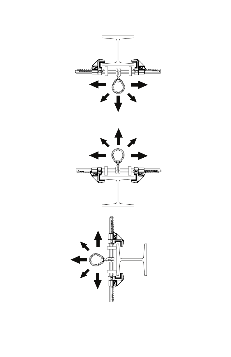
2. The anchorage connector may only be loaded as shown in the LOADING CONDITIONS DIAGRAM.
3. The anchorage connector is designed to be used in temperatures ranging from -40ºF to +130ºF (-40°C to +54°C).
4. Do not expose the anchorage connector to chemicals or harsh solutions which may have a harmful eect.
5. Do not alter or modify this product in anyway.
6. Caution must be taken when using any component of a fall arrest, work positioning, rope access, or rescue system near
moving machinery, electrical hazards, sharp edges, or abrasive surfaces, as contact may cause equipment failure, personal
injury, or death.
7. Do not use/install equipment without proper training by a“competent person”as defined by OSHA 29 CFR 1926.32(f) and
EN795:2012 Annex A1.
8. Do not remove the labeling from this product.
9. Additional requirements and limitations may apply depending on anchorage type and fastening option utilized for
installation. All placements must be approved by an engineer or other qualied person.
10. This anchorage connector should not be used as part of a horizontal lifeline system that has not been designed and/or
approved to be used with 5,000-lbf (22kN) anchorage connectors.
11. The anchorage connector should only be used as intended (see PURPOSE).
12. If attaching the anchorage connector to the support structure by methods other than instructed, the attachment must be
certied by a qualied person to meet the requirements of the system that will connect to the anchorage connector.
Read This Instruction Manual Carefully Before Using This Equipment.

INSTALLATION:
1. Locate a structural steel beam ange capable of withstanding a 5,000-lbf. static load or
meeting OSHA and EN 795 2012 requirements for a safety factor of two.
2. Push in on the latch handle to allow the adjustable hook to move.
3. Keeping the unit perpendicular to the beam, t the hooks over the edges of the beam ange.
4. Slide the adjustable hook so that both hooks are snug against the beam ange.
5. Pull back the adjustable hook to ensure the ratchet teeth are fully seated in the nearest
ratchet notches.
6. Tug, rock, and twist the anchor in all directions to ensure that it cannot come o of the ange.
*Always re-adjust according to Installation steps 1-6 when moving to a new or dierent sized
beam.
** D-ring is centered on the anchorage connector for ease of sliding on beam anges.
Particularly in rope access applications, bodyweight may disengage the centering feature in
some loading conditions. This is not a safety concern, but it may aect usability.
PERFORMANCE:
Minimum Breaking Strength: 5000-lbf (22kN)
Maximum Capacity: One worker when
used as a single point anchorage connector
for personal fall arrest or restraint system
DIMENSIONS:
Weight: 3.3-lbs (1504g)
Beam Flange Width Range: 3.5 -14 inches
Beam Flange Thickness: .25 - 1.25 inches
REGULATORY COMPLIANCE:
ANSI Z359.18 Type A, ANSI Z359.7-2019,
EN 795:2012 Type B (CE 0161)
OSHA 29 CFR 1926.502, OSHA 29 CFR 1910.140
EU 2016/425
COMPONENT MATERIALS:
Aluminum: Cross Bar
Bronze: Clamps
Stainless Steel: D-Ring Bracket
Zinc Plated Steel: D-Ring, Spring, Hardware
Adjustable Directions
Notches
Latch Handle
Notches
Latch Handle
Adjustable Hook Adjustable Hook
COMPATIBILITY LIMITATIONS
Anchorage connector must only be coupled to compatible connectors. OSHA 29 CFR 1926.502, 1910.140, and EN 362 prohibits
snaphooks from being engaged to certain objects unless two requirements are met: it must be a locking type snaphook, and
it must be “designed for” making such a connection. “Designed for” means that the manufacturer of the snaphook specifically
designed the snaphook to be used to connect to the equipment listed. The following connections must be avoided, because
they can result in rollout* when a nonlocking snaphook is used:
• Direct connection of a snaphook to horizontal lifeline.
• Two (or more) snaphooks connected to one D-ring.
• Two snaphooks connected to each other.
• A snaphook connected back on its integral lanyard.
• A snaphook connected to a webbing loop or webbing lanyard.
• Improper dimensions of the D-ring, rebar, or other connection point in relation to the snaphook dimensions that
would allow the snaphook keeper to be depressed by a turning motion of the snaphook.
*Rollout: A process by which a snaphook or carabiner unintentionally disengages from another connector or object to
which it is coupled. (ANSI Z359.0-2007)

LOADING CONDITIONS DIAGRAM
Placement at or below a user’s working height requires integration of an ANSI Z359 compliant
energy absorbing connecting component (Energy Absorbing Lanyard or Self Retracting Lifeline)
and free fall limits of the connecting component must be followed. The beam anchor must be
attached to the I-beam ange facing the user (top ange if above, bottom ange if below, etc.).

WARNING LABEL LOCATIONS
WARNING: It is essential to the safety of the end user that the seller of this device
include all instructions pertaining to the proper use, maintenance and inspection of
the device in the language of the country in which the product is to be sold.
BREAKING STRENGTH: 5000 lbf (22.2 kN)
MFG: MM/YYYY
WARNING: All persons using this equipment must read, understand and follow
all instructions. Failure to do so could result in serious injury or death.
QUALITY CONTROL AND INSPECTIONS
Units produced are designed and manufactured according to the standard(s) on the product label
(CE, ANSI, CSA, etc.). Product designs are validated through conformity assessments required ac-
cording to the standard(s) to which the product is labelled (Declaration of Conformity, Certicate of
Conformity, etc.). Quality control during production is completed by sampling a minimum of three
units per batch, prior to acceptance of the batch, and validating dimensions and markings. Samples
are statically tested according to the applicable standard before batches are accepted or released.
Outgoing products are inspected by Quality Control, minimum 3 per order, for acceptance validat-
ing markings, labels, packaging, and documentation. The Module C2 procedure for annual product
checks as stated in Regulation (EU) 2016/425 Annex VII is conducted by the notied body AITEX
(0161).
Hybrid Beamer
Model: A555000CE
Batch # XXXX
Compliance: OSHA 1926.502, OSHA 1910.140, ANSI Z359.18 Type A, ANSI Z359.7(19)
EN 795:2012 Type B CE 0161
Stainless Steel, Aluminum, Zinc Plated Steel, Bronze
Pat # US 8,312,966 / US 8,646,575 / US 8,973,705 B2
MAX
1(888) 523-3371
P/N 112573-16 REV I
P/N 112573-17 REV I
0161
WARNING: ALL USERS OFTHIS EQUIPMENT MUST READ AND
UNDERSTAND ALL INSTRUCTIONS. FAILURE TO DO SO MAY
RESULT IN SERIOUS INJURY OR DEATH. USERS SHOULD BE
FAMILIAR WITH PERTINENT REGULATIONS GOVERNING THIS
EQUIPMENT. ALL USERS OF THIS PRODUCT MUST BE PROPERLY
INSTRUCTED ON HOW TO USE THE DEVICE. AVOID CONTACT
WITH PHYSICAL HAZARDS (THERMAL, CHEMICAL, ELECTRICAL,
ETC.). MAKE ONLY COMPATIBLE CONNECTIONS.
Serial#

Annex II Regulation (EU)
2016/425
795:
2012
1.1.1. Ergonomics N/A
1.1.2.1. Optimum level of protection N/A
1.1.2.2. Classes of protection appropriate to different
levels of risk N/A
1.2.1.1.Suitable constituent materials 4.2
1.2.1.2.Satisfactory surface condition of all PPE
parts in contact with the user N/A
1.2.1.3.Maximum permissible user impediment N/A
1.3.1.Adaptation of PPE to user morphology N/A
1.3.2.Lightness and strength 4.1.6
1.3.3.Compatibility of different types of PPE intended
for simultaneous use N/A
1.3.4.Protective clothing containing removable
protectors N/A
1.4.Manufacturer’s instructions and information 7
2.1.PPE incorporating adjustment systems 4.4.3.5
2.2.PPE enclosing the parts of the body to be
protected N/A
2.3.PPE for the face, eyes and respiratory system N/A
2.4.PPE subject to ageing N/A
2.5.PPE which may be caught up during use N/A
2.6.PPE for use in potentially explosive atmospheres N/A
2.7.PPE intended for rapid intervention or to be put
on or removed rapidly N/A
2.8.PPE for intervention in very dangerous situations N/A
2.9.PPE incorporating components which can be
adjusted or removed by the user 4.1.5
2.10.PPE for connection to complementary equip-
ment external to the PPE N/A
2.11.PPE incorporating a uid circulation system N/A
2.12.PPE bearing identication markings or indica-
tors directly or indirectly relating to health and safety 6
2.13.PPE capable of signalling the user’s presence
visually N/A
2.14.Multi-risk PPE N/A
3.1.1.Impact caused by falling or ejected objects and
collisions of parts of the body with an obstacle N/A
3.1.2.1.Prevention of falls due to slipping N/A
3.1.2.2.Prevention of falls from a height 4.4.2.3
3.1.3.Mechanical vibration N/A
3.2.Protection against static compression of a part
of the body N/A
3.3.Protection against mechanical injuries N/A
3.4.1.Prevention of drowning N/A
3.4.2.Buoyancy aids N/A
3.5.Protection against the harmful effects of noise N/A
3.6.Protection against heat and/or re N/A
3.6.1.PPE constituent materials and other compo-
nents N/A
3.6.2.Complete PPE ready for use N/A
3.7.Protection against cold N/A
3.7.1.PPE constituent materials and other compo-
nents N/A
3.7.2.Complete PPE ready for use N/A
3.8.1.Insulating equipment N/A
3.8.2.Conductive equipment N/A
3.9.1.Non-ionising radiation N/A
3.9.2.1.Protection against external radioactive
contamination N/A
3.9.2.2.Protection against external irradiation N/A
3.10.1.Respiratory protection N/A
3.10.2.Protection against cutaneous and ocular
contact N/A
3.11.Diving equipment N/A

MAINTENANCE, CLEANING AND STORAGE
Cleaning periodically will prolong the life and proper functioning of the product. The frequency
of cleaning should be determined by inspection and by severity of the environment. Clean with
compressed air and/or a sti brush using plain water or a mild soap and water solution. Do not use
any corrosive chemicals that could damage the product. Wipe all surfaces with a clean, dry cloth
and hang to dry, or use compressed air. When not in use, store anchorage connectors in a cool, dry,
clean environment, out of direct sunlight and free of corrosive or other degrading elements.
*It is essential for the safety of the end user that if this product is re-sold outside the original
country of destination the reseller shall provide instructions for use, maintenence, and for periodic
examination and repair in the language of the country in which the product is to be used.
Inspection:
Ocial inspections must be made at least annually. The inspection must be performed by a
competent or qualied person other than the intended user. If severe environmental conditions
exist then inspections must be carried out more frequently. All inspection results must be logged
in the space provided above. It is recommended that the anchor device is marked with the date of
the next or last inspection. This product, according to EN 795:2012, does not have an expiry date
providing before use and annual inspection are satisfactory.
1. Ensure all labeling is axed to the unit.
2. Inspect anchoring system for signs of damage or wear.
3. Ensure the ring is free to swivel and pivot.
4. Check for excessive play and wear on the retaining bushing
(Bushing should not wiggle or rotate.)
5. Ensure latches engage and disengage properly.
6. Record inspection results in the space provided above.
*If inspection reveals any damage that could aect the strength or operation of the
device, inadequate maintenance, or an unsafe condition, proper disposal is required.
The anchorage connector must be rendered unusable and then properly discarded.
MODEL NUMBER:
DATE OF MANUFACTURE:
INSPECTION AND MAINTENANCE LOG
Date Part Number Comments Inspector Name
Inspect retaining
bushing for wear
or damage.

Zarges
Zargesstraße 7
82362 Weilheim, Germany
+49 881 687 - 100 www.zarges.de
105548-11 REV J
Notied Body responsible for the EU type examination and ongoing
conformity:
AITEX
Plaça Emili Sala, 1,
03801 Alcoi,
Alicante, Spain,
+34 965 54 22 00
0161
Table of contents