Zebra ZebraStat ZS-2 User manual

ZebraStat
Operation Manual
®
Model ZS-2

2Contents
Safety Information........................................3
Using the ZebraStat.............................4-5
Troubleshooting Electronic Boards..........6-7
Voltage Problems......................................8-9
Feature Identification (Photo)................10-11
Continuity Mode....................................12-13
AnalysisMode.......................................14-15
Activation Mode....................................16-17
CircuitProtection........................................18
Avoiding Problems......................................19
Warranty......................................Back Cover
Your ZebraStat will give you longer life if you
treat it carefully, like any other sensitive tool.
Maximum Input Voltage.........................28 Volts
Maximum Current Through Unit............5 Amps
Overall Circuit Protection.............5 A. @ 24 V.
White Wire Circuit Protection.......3 A. @ 24 V.
Unit Size............................8”L. x 5”W. x 2.25”H.
UnitWeight...............................................18 oz.
Warranty................One Year Limited Warranty
Specifications

Safety Information
Please read these instructions before using
your ZebraStat.They contain information to
protect you, your customers, and their prop-
ertyfrom harmordamage. Understanding the
proper use of this tool may also assist you to
make quicker and more accurate diagnostics
on the equipment that you service.
Maximum Input Voltage.....................28 Volts
Maximum Current Through Unit.........5Amps
• NEVER connect any lead to (nor allow
any unconnected lead to touch) Line Volt-
age, or any voltage higher than 28 Volts.
• Do not perform an activation that a normal
thermostat could not perform, such as calling
for heating and cooling simultaneously.(Un-
less you are servicing a heat pump.)
• If the equipment requires it, respect staging
precedence. (i.e.: Do not turn on stage two if
stage one is not already activated.)
• Do not allow your ZebraStat to get wet. If it
does get wet; dry it thoroughly before using.
3

Using the ZebraStat
4
To use your ZebraStat, follow these steps:
1) Decide the mode that you want to use
2) Hook up appropriate leads to equipment
3) Manipulate Mode & Component switches
4) Observe the LED’s and equipment tested
Explanation of steps:
1) Mode. ZebraStat operates in 3 different
modes.You caneasilyleaveithookedupand
use all 3 modes on the same equipment as
needed. The 3 modes are:
• Continuity - This mode tests that the wires
that you connect to electrically ‘go some-
where’. For instance, the wire that you con-
nect to the FAN lead normally goes through a
fan relay, and the continuity mode will tell you
if there is a continuous circuit through that re-
lay on the other end of the equipment’s wire.
• Analyze - This mode simply displays the
power flowing through the circuits that your
leads are connected to. First, the red LED’s
tell you power is available in the equipment.
YellowLED’slightwhenthe thermostatis call-
ingforheating,cooling,fan,orreversingvalve.

Using your ZebraStat (continued)
• Activate -This mode is like having a remote-
control thermostat. Technicians often use it
when the thermostat is not easily accessible:
when making a diagnosis or repair to a unit in
an attic, basement, roof,or new construction
where the thermostat hasn't been installed yet.
2) Hook-Up. Start with the Mode Switch in the
ANALYZE position and have all component
switches OFF. The hookup of Zebra-Stat’s
leads is the same for all modes. First, connect
the component lead’s alligator clips to their re-
spectivewiresattheequipment.(Commonuses
of wire colors are listed below the component
switches.However,youcanuseanyofthewires
to test any other 24V function, like ‘Emergency
Heat’.) Then connect the Red and Blue leads
totheequipment’s24V power, observingpolar-
ity. All modes exceptANALYZE require that all
thermostat functions be OFF.
3)& 4)Manipulate Controls& ObserveLED’s
&Equipment. Seethefollowingsections(Con-
tinuity, Analysis, or Activation) for the proper
steps to follow next.
5

6Troubleshooting
Electronic Boards
A blown fuse on an electronic control board
presents special challenges. Rather than just
replacingthefuse(andpossiblywatchit‘blow’
again) the ZebraStat offers a diagnostic al-
ternative. The White wire (the HEAT1 circuit)
has a special function built into it. Between
the Red and White wires is a low-amp, auto-
reset, solid-state 'circuit breaker'. This circuit
breaker is set to ‘trip’ at 3 Amps,providing a
safe alternative to repeatedly replacing fuses
while looking for the cause.
Here’s how it works: Remove the blown fuse.
Attach the Red and the White leads of the
ZebraStat to the board or fuseholder where
the fuse was. No other leads should be at-
tached for this mode. Turn the mode switch
to ACTIVATE and turn ON the HEAT1 com-
ponent switch. All other component switches
should remain off. Now, the ZebraStat’s cir-
cuits are acting as a 'circuit breaker'with a rat-
ing of 3 Amps.

Troubleshooting (continued) 7
If the current flowing into the Zebrastat
through these two wires should exceed 3
Amps, the breaker will ‘trip’, and the lower Trip
LED will light. The breaker will stay in this
‘tripped’ condition until the power is removed
from one of the leads for about 15 seconds.
(Some electronic thermostats may start a set/
reset cycle as they lose power and drop out.)
A typical problem causing a fuse to blow on
one of these boards is a shorted thermostat
wire. Diagnosing which wire is accomplished
much easier with a ZebraStat: Hook up the
ZebraStat as described above. When the
Zebrastat’s breaker trips, remove power to
the system for 15 seconds. While the power
is off remove one thermostat wire at a time
from the control board, turning on the power
again after each disconnection. When theTrip
LED does NOT light up after removing a wire,
the suspect circuit has been found. If all ex-
ternal low voltage control wires are removed,
and the Trip LED still lights, it’s time to suspect
that the board itself may have a problem.

Voltage Problems
Voltage problems in a system are frequently
overlooked, but are very easy to find. For in-
stance, many technicians don’t compare the
current draw on contactors when replacing
one. In most cases there won’t be a problem,
but if the transformer is already close to its
output capacity, and the new contactor re-
quires a higher current level to close, inter-
mittentproblems arelikelytoarise,especially
ifthelinevoltagedropsafewpercentbecause
of high demand, say, on a hot afternoon.
The ZebraStat has a built-in voltage monitor
section that makes it easy to tell if the voltage
being supplied at the Red and Blue leads is
adaquate.(Thesevoltagescouldeasilybede-
terminedwithavoltmeter,ofcourse;butmany
technicians do not check for low-voltage lev-
elswhileunderload,eventhough theycould.)
Getting used to glancing at the VOLTAGE
section of the ZebraStat may help you de-
tect some of these problems before they ac-
tually causea fault.
8

Voltage Problems (continued)
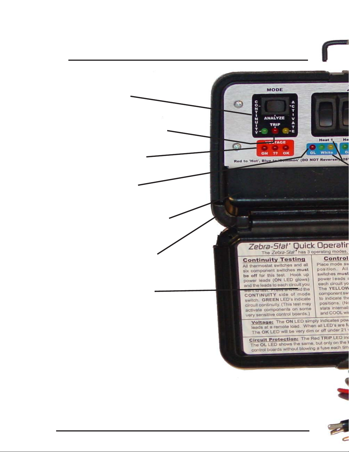
There are 3 red LED’s in the voltage section:
ON, ??, and OK. The ON LED will light when
thevoltageapplied tothe powerinputleads is
at least 8 volts. The ?? (Questionable) LED
glows about half-brightness at 19.5 volts, and
full-brightness at 20.5 volts. The OK LED
glows about half-brightness at 21.5 volts, and
is fully bright at 23 volts.
Any time that you are using the ZebraStat
and notice that the OK LED isn’t fully lit, you
may want to check the voltage level at the
component that is farthest away from the sys-
tem transformer while under load. (The volt-
agedropfromthewireswillbegreatestthere.)
IftheOK LEDisn’tglowingatleasthalf-bright-
ness, there is the potential that higher tem-
peratures (higher wire resistance) and lower
line voltage (due to high demand) may cause
that component to not be able to close fully,
or, in the case of a reversing valve, not be
abletochangepositions. Ahigher-ratedtrans-
former may be called for, or larger wiring.
9

10 Feature Identification
Mode Switch
Voltage Monitor
Lower Trip LED
Lead Compartment
Magnet (on back)
Quick Reference
ZebraStat Model ZS-2
Upper Trip LED (Red)

on Hanging Hook
Component
Switches
Leads
Component
Displays
Velcro Strap
-2
Continuity LED’s
(6 - Green)
Activation LED’s
(6 - Yellow)
Wire Color
Codes
11

Continuity Mode
12
Continuity Mode tests that the wires your
ZebraStat’sleads areconnectedto‘gosome-
where’electrically. For instance, the wire that
youconnected theFAN leadto normallygoes
through a fan relay. Using this mode will tell
youifthereisacontinuouscircuitthrough that
relay on the other end of the wire.
1) Turn all thermostat functions to OFF.
2) Turn all the ZebraStat’s component
switches to OFF, and put the Mode Switch in
the ANALYZE position.
3)Attach the ZebraStat’s component leads to
the appropriate equipment wires, then attach
the Red and Blue power leads to the
equipment’s 24VAC hot and common wires,
observing polarity.
4) Verify that no yellow LED’s are lit before
proceeding. If they are, recheck thermostat
for ON (or wiring for shorts) before continuing.

Continuity (continued)
Caution: The continuity mode passes a very
small amount of current to ‘test’ each of the
circuits that it is connected to. As more mod-
ern equipment uses computer-type process-
ing boards to control equipment, some may
be designed that have functions that might be
activatedbythe ZebraStat’stiny(about7mil-
liamps)ofcurrenttotestthedifferentcircuits.
Be aware that some circuits might possibly
be activated while testing in Continuity Mode.
(For instance, don’t test continuity on equip-
ment if your hand is near the fan. It could start
during this test. Ditto for the condensing unit.)
5) Place the Mode Switch to the Continuity
Position. Green LED’s should illuminate un-
der each component being tested. No light
probably indicates an incomplete circuit. A
yellow LED indicates the component under
test is currently ACTIVATED; the LED will
change back to green when activation is re-
moved. Control boards on some new variable
speed units may give false positive indications.
13

14 Analysis Mode
Analyzis Mode simply displays any control
powerthatisbeing sentto thecircuitsthatyour
leads are connected to. The red LED’s will
indicate the level ofAC power available at the
equipment. Yellow component LED’s will illu-
minate on each circuit that is currently ener-
gized. This mode is often used by a tech to
isolate the general area of a problem.
For instance, you turned the FAN switch on at
the thermostat, but the fan does not start.
Observing a lit yellow LED in the FAN section
of the ZebraStat connected to the equipment
would tell you that the signal is getting to the
equipment (suggesting a problem inside the
equipment). If the corresponding LED was
notlit,(thesignalwasnotgettingto theequip-
ment) it suggests that the problem may be in
the thermostat or it’s associated wiring.
1) Turn all of the ZebraStat’s component
switches to OFF, and put the Mode Switch in
the ANALYZE position.

Analysis (continued)
2) Attach the ZebraStat’s component lead’s
alligator clips to the appropriate equipment
wires, then attach the Red and Blue power
leadsto theequipment’s 24VAChot andcom-
mon wires, observing polarity.
3) Notice which yellow LED’s are illuminated
under their component switches. (All of the
component switches must be OFF.) These
LED’s indicate which circuits are currently re-
ceivingpower. Techniciansoftenusethisfea-
ture to troubleshoot: (a) cross-wired thermo-
stat wires (for instance, if thecondensing unit
starts when the fan switch is activated on the
thermostat) or; (b) shorted thermostat wires
(for instance, if the two cooling stages start
simultaneously when only one is being called
for; or a continuously operating fan). NOTE:
Many thermostats pre-connect FAN & COOL
leads when set to ‘Cool’ mode, etc.
4) Manipulate the thermoat’s switches and
observe the results on the ZebraStat to verify
that all functions are working properly.
15

16 Activation Mode
Activationmodeissimilairtohavingaremote-
controlled thermostat. Technicians often use
this mode when the thermostat is not easily
accessible, as in when making a diagnosis or
repair to equipment in an attic, basement, on
a roof, or other location remote from the area
where the thermostat is located.
1) Turn all thermostat functions to OFF.
2) Turn all of the ZebraStat’s component
switches to OFF, and put the Mode Switch in
the ANALYZE position.
3) Attach the ZebraStat’s component lead’s
alligator clips to the appropriate equipment
wires, then attach the Red and Blue leads to
theequipment’s24VAChotandcommonwires,
observing polarity.
4) Verify that no yellow LED’s are lit before
proceeeding.Ifanyare,recheckthermostatfor
ON (or wiring for shorts) before continuing.

Activation (continued)
Caution: Remote activation can surprise an-
othertechnicianworkingelsewhereonrelated
equipment. Communicate your intentions to
anyone else involved. For instance, when re-
motely activating the cooling stages of a sys-
tem; you don’t want to start a fan or compres-
sor that someone may be inspecting.
5) Turn the Mode Switch to ACTIVATE.
6) Turn on component switches as appropri-
ate.Usecaretoactivatecomponentslogically;
for instance, do not turn on BOTH a heating
and a cooling stage at the same time. Like-
wise, you usually turn on FAN when a
COOLing stage is active. Finally, respect the
sequence of stages; don’t activate stage 2
(cooling or heating) unless stage 1 is active.
NOTE: Some systems may have other com-
ponents, like ‘Emergency Heat’ that you may
test. You canuseanyofthe four‘stage’wires,
(HEAT 1 & 2, etc.) to test these components.
17

18 Circuit Protection
Your ZebraStat provides circuitprotection in
two ways. Each uses a solid-state, automati-
cally-resetting circuit breaker device. The
white test lead is protected with a 3 Amp de-
vice. You can learn more about its use in the
“Troubleshooting Electronic Boards” section.
The second device provides an overall pro-
tection for the ZebraStat. It is rated at ap-
proximately 5 Amps at 28 Volts. (150VA)
If you inadvertantly hook up the ZebraStat’s
power input leads using an incorrect ‘polarity’
and attempt to use the Activation Mode, or if
you allow a loose ‘hot’ lead to touch ground,
you will probably ‘trip’ this circuit protection,
shutting down the ZebraStat, and turning on
the red TRIP LED. The unit will remain in the
tripped condition until you remove all power
to the unit for about 15 seconds. Before re-
connecting, discover and correct the condi-
tion that caused the trip in the first place.
This protection device is not meant to protect
the unit from higher voltages than 28 Volts.

Avoiding Problems
1) The “power-in” wires (RED & BLUE) ARE PO-
LARIZED,eventhoughit’s anACcircuit!The RED
lead must connect to the equipment’s HOT wire
(usually red), and the BLUE lead must connect to
the equipment’s COMMON wire (usually brown or
blue). REVERSINGTHESELEADS CAN CAUSE
THE ZebraStat’s CIRCUIT BREAKER TO TRIP.
2) If you are getting a strange LED indication in
either the CONTINUITY or ANALYZE modes, it
could be caused by having one of the ZebraStat’s
component switches ON. Leave all six switches
OFF for testing in either of these two modes.
3) In the CONTINUITY or ACTIVATE modes, all
thermostat switches should be OFF, and it must
not be calling for any heating or cooling. Strange
LED indications may appear on the ZebraStat if
all thermostat functions aren’t completely ‘OFF’.
4) Some thermostats internally connect their ‘G’
and ‘Y’ terminals when in ‘Auto Fan’. (This will be
noticedin theCONTINUITYorANALYZE modes.)
5) Some thermostats may activate the reversing
valve as soon as they are switched into ‘Heat’ or
‘Cool’. (CONTINUITY orANALYZE modes.)
19

One Year Limited
Warranty
For a period of one (1) year from the origi-
nal end-user’s date of purchase, Zebra
Instruments warrants that this tool will per-
form as described. Should you encounter
any problems, please contact us and we
will attempt to resolve your problem as
quickly as possible. This resolution may
include replacement; exchange; or repair
of a defective unit, at our option. This war-
rantydoesnotapplytounitsthathavebeen
exposed to: voltages and/or currents that
are higher than those specified in this
manual; abuse or rough handling; or dam-
age from moisture or exposure to chemi-
cals. Out-of-warranty repairs are available
fora nominalchargeplus shipping.Please
contact us for a return authorization num-
ber before returning any unit.
Zebra Instruments 512.869.7000
PO Box 3000 #1, Georgetown, TX 78627
www.ZebraInstruments.com
©2004 Zebra Instruments
Table of contents
Other Zebra Remote Control manuals