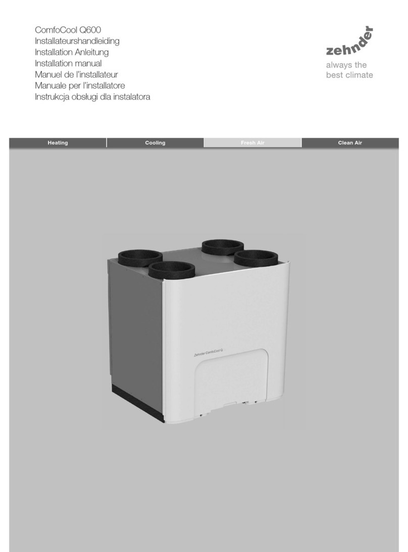
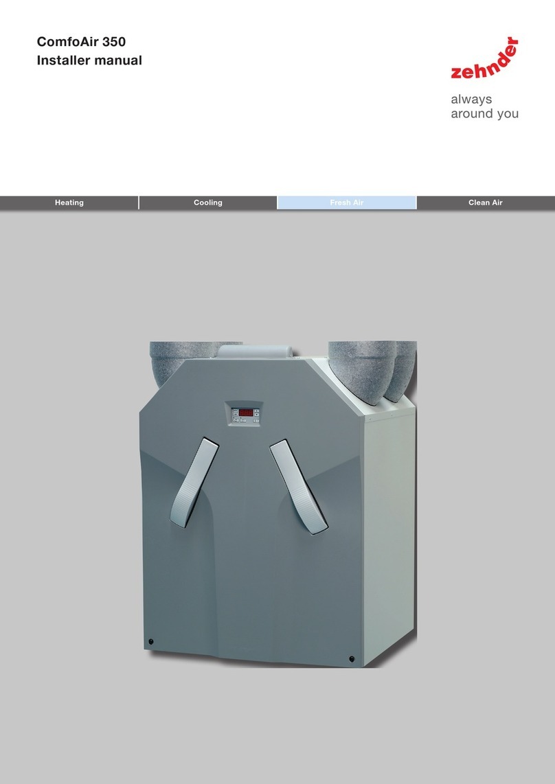
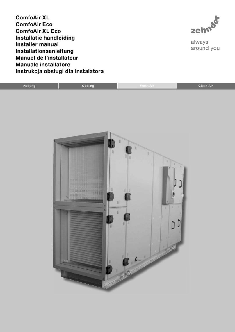
Zehnder Rittling ComfoAir 800 User manual

ComfoAir XL
ComfoAir Eco
Manual
Cooling Fresh Air Clean AirHeating

2 - EN
Foreword
Read this document carefully before use.
This document provides all the information
required for the safe and optimal installation and
maintenance of the ComfoAir XL and ComfoAir Eco
with software version 3.07 or higher. In this following
document they will be referred to as “the unit”.
The unit is subject to continuous development and
improvement. As a result, the unit may slightly differ
from the descriptions.
The following pictograms are used in this
document:
Point of attention.
Risk of:
- damage to the unit;
- performance of the unit is compromised if
instructions are not observed carefully.
Risk of personal injury for the user.
Maintenance
Questions
Please contact the supplier if you have any questions
or would like to order a new document or new filters.
The contact details of the main supplier can be
found at the end of this document.
All rights reserved.
This documentation has been compiled with the utmost care. The publisher cannot be held liable for any damage
caused as a result of missing or incorrect information in this document. In case of disputes the Englisch version of
these instructions will be binding.

2 - EN EN - 3
Table of contents
Foreword ...................................................................................................................................................................2
1. Safety instructions ................................................................................................................................................... 5
2. Transport and unpacking......................................................................................................................................... 5
3. Installation conditions .............................................................................................................................................6
4. Technical specifications ..........................................................................................................................................6
4.1 NTC sensors........................................................................................................................................................ 6
4.2 Configuration ComfoAir XL standard...................................................................................................................7
4.3 Configuration ComfoAir XL A (modulated frost bypass in supply air) ..................................................................8
4.4 Configuration Main PCB......................................................................................................................................9
4.5 Configuration I/O PCB....................................................................................................................................... 10
4.6 Operating principle diagram .............................................................................................................................. 11
5. Installation ............................................................................................................................................................. 12
5.1 Mounting ........................................................................................................................................................... 12
5.2 Air ducts............................................................................................................................................................ 12
5.3 Condensation drain ........................................................................................................................................... 13
5.4 Siphon heating .................................................................................................................................................. 13
5.5 Constant flow control ........................................................................................................................................ 14
5.6 Sensor (0..10V) control....................................................................................................................................... 14
5.7 Constant pressure control................................................................................................................................. 14
5.8 Switch to second setpoint................................................................................................................................. 14
5.9 Summer night ventilation................................................................................................................................... 15
5.10 Modbus ............................................................................................................................................................. 15
5.11 Manually switching functions off ....................................................................................................................... 15
5.12 Reset malfunction button .................................................................................................................................. 15
5.13 Failure contact................................................................................................................................................... 15
5.14 Fire contact ....................................................................................................................................................... 15
5.15 Dirty filter alert .................................................................................................................................................. 15
5.16 External supply air temperature sensor............................................................................................................. 16
5.17 Battery .............................................................................................................................................................. 16
6. Commissioning ....................................................................................................................................................... 17
6.1 Air volume control (M02, M12-04) ...................................................................................................................... 17
6.2 Ventilation time clock (M60)............................................................................................................................... 18
6.3 PI control units .................................................................................................................................................. 19
6.4 Siphon heating (M50, M06 option 7).................................................................................................................. 19
6.5 Constant flow control (M02-10option 0)............................................................................................................. 19
6.6 Sensor (0..10V) control (M02-10 M04-11, M09)................................................................................................... 20
6.7 Constant pressure control (M02-10, M04-11, M09) ........................................................................................... 20
6.8 Switch to second setpoint (M02, M05 option 25)............................................................................................... 20
6.9 Summer night ventilation (M02-09, M05 option 21, M06 option 10)................................................................... 21
6.10 Modbus (M80) ................................................................................................................................................... 21
6.11 Manually switching functions off (M05) ............................................................................................................. 21
6.12 Reset malfunction button (M05 option 23, M06)................................................................................................ 21
6.13 Failure contact (M05 option 18, M06) ................................................................................................................ 21
6.14 Fire contact (M02, M05 option 20/24)................................................................................................................ 21
6.15 Dirty filter alert (M70, M06)................................................................................................................................22
6.16 External supply air temperature sensor............................................................................................................. 22
6.17 Battery (M06, M07)............................................................................................................................................ 22

4 - EN
6.18 Temperature control (M10)................................................................................................................................. 23
6.19 Frost protection................................................................................................................................................. 24
6.20 Preset settings .................................................................................................................................................. 24
6.21 Parameters ........................................................................................................................................................ 25
M1 – Actual Controls ......................................................................................................................................... 25
M2 – Ventilation................................................................................................................................................. 26
M3 – n/a ............................................................................................................................................................ 26
M4 – Ventilation settings ................................................................................................................................... 26
M5 – Digital Input settings................................................................................................................................. 27
M6 – Relay settings ........................................................................................................................................... 27
M7 – Analog output settings.............................................................................................................................. 28
M8 – Communication settings ........................................................................................................................... 28
M9 – Analog input settings ................................................................................................................................ 28
M10 – Temp Control .......................................................................................................................................... 29
M11 – Bypass settings....................................................................................................................................... 29
M12 – Heat Exchanger settings ......................................................................................................................... 29
M13 – Pre heater frost settings.......................................................................................................................... 30
M20 – Failures ................................................................................................................................................... 30
M50 – Miscellaneous ......................................................................................................................................... 30
M60 – Time clock .............................................................................................................................................. 31
M70 – Filters...................................................................................................................................................... 31
M80 – Modbus Communication......................................................................................................................... 32
M90 – SD Card .................................................................................................................................................. 32
M99 – Service.................................................................................................................................................... 32
7 Operation ................................................................................................................................................................ 33
7.1 Using the display on the main PCB ...................................................................................................................33
7.2 Using the SD Card on the main PCB (M90) .......................................................................................................34
7.3 Service parameter (M99) ................................................................................................................................... 34
8 Maintenance
7.3 Service parameter (M99)
.................................................................................................................................................... 35
8.1 Filters .........................................................................................................................................................36
8.2 Condensation drain(s) ................................................................................................................................36
8.3 Casing
8.2 Condensation drain(s)
........................................................................................................................................................ 37
8.4 Heat exchanger .......................................................................................................................................... 37
8.5 Fans
8.4 Heat exchanger
........................................................................................................................................................... 38
8.6 Battery ....................................................................................................................................................... 38
9. Failures....................................................................................................................................................................39
10 CE certification and warranty ...............................................................................................................................41
I Installation report................................................................................................................................................... 42
II Maintenance Log .................................................................................................................................................... 42

4 - EN EN - 5
1. Safety instructions
Always follow the safety regulations, warnings,
comments and instructions given in this document.
Personal injury or damage to the unit can arise
from non-compliance with the safety regulations,
warnings, comments and instructions in this
document.
�The unit may only be installed, connected,
rendered operational and maintained by an
appropriately approved installer, unless otherwise
indicated in this document;
� Only a recognized cooling-technology fitter is
permitted to carry out work on the DX battery;
� Installation of the unit must be carried out
in accordance with the general and locally
applicable construction, safety and installation
instructions of the local council, electricity and
water boards or other agencies;
� The unit is only suitable for connection to 230V
50/60Hz mains; With the exception of the unit size
6000, which is suitable for 400V 50/60Hz
(3 phases);
� The unit must be connected to a separate group in
the fuse box;
� When carrying out any work on the unit, make
sure the power is disconnected and cannot be
inadvertently reconnected;
The primary circuit-breaker can be locked
with a padlock.
� Always take ESD-inhibiting measures when
dealing with PCBs, (printed circuits boards) such
as wearing an antistatic wristband;
� Store this document for the entire working life of
the unit.
Safety provisions and measures
� The unit cannot be opened without using tools;
� It should not be possible to touch the fans,
therefore ducting must be connected to the unit at
a minimum duct length of 900mm.
2. Transport and unpacking
Take the necessary precautions when transporting
and unpacking the unit and make sure the packing
material is disposed of in an environmentally friendly
manner.
Fork lift truck instructions
� The bottom of the unit must be supported during
transport;
� Make sure the forks are slid completely under the
unit, in order to avoid denting the housing;
� Check whether access to the area is not
obstructed by excessively small passages etc.
Hoisting instructions
� Hoisting the unit may only be carried out by
persons authorized to do so;
� Check the dimension sketch and the weight given
on the unit;
� Hoist the appliance by means of the hoisting lugs
on the base frame;
� When hoisting, protect the housing from denting
by the hoisting strap. A suitable load spreader can
be used for this purpose;
MAX.60°
� Remove the hoisting lugs after placing the unit.

6 - EN
Checking the delivery
Contact your supplier immediately in case of damage
or an incomplete delivery. The delivery should at
least include:
� The unit; Check the identification plate to ensure
that it is the required type.
� Seal cap, seal plug, cable feed in packaging;
� Hoisting instructions (attached to the operating
side);
� Documentation.
The unit can be supplied in the following sizes:
ComfoAir 800 ComfoAir 3300
ComfoAir 1500 ComfoAir 4400
ComfoAir 2200 ComfoAir 6000
Meaning of the suffixes found on the
identification plate:
Suffix Explanation
ComfoAir XL
ComfoAir Eco
Product family name
2200 Product type name (air
volumes in m3/h)
CFE The unit has a counterflow
plate exchanger installed as
default.
AThe unit has a modulated frost
bypass installed in the outdoor
air as default.
LThe unit is a left-hand version.
(Exhaust/Supply Left)
RThe unit is a right-hand
version. (Exhaust/Supply
Right)
BThe unit has an open/close
bypass installed as default.
BM The unit has a modulating
bypass installed as default.
IThe unit is suitable for indoor
installation;
OThe unit is suitable for outdoor
installation;
PF The unit has a panel filter
installed as default.
BF The unit has a bag filter
installed as default.
CL The unit has a cooler installed
as default.
PRH The unit has a pre heater
installed as default.
POH The unit has an postheater
installed as default.
DMP ODA The unit has an outdoor air
damper installed as default
DMP EHA The unit has an exhaust air
damper installed as default
The identification plate detailing information on the
unit can be found on the operating side of the unit.
Suffixes between brackets mean there is space
reserved for installing the specified function.
3. Installation conditions
In order to determine whether the unit can be
installed in a certain area, the following aspects
must be taken into account:
� Check whether the admissible load (kg/m2) of the
roof or floor is sufficient to bear the given weight
of the unit;
� The system must be fitted to allow sufficient
room around the unit for the air duct connections,
condensation drain as well as for carrying out
maintenance activities like a filter exchange;
To ensure components can be replaced, at least
one casing‘s width of free space is required.
� The condensation must be drained off frost-free,
at a gradient and incorporate an air seal (U-bend
or dry siphon);
� The room must offer the following provisions:
- Air duct connections;
- Electrical power connection;
- Provisions for the condensation drain;
- Facilities for battery or batteries.
4. Technical specifications
The units specific technical specifications are added
separately to the unit. This can includes the following
information:
� Dimension sketch;
� Wiring diagram;
� Air specifications;
� Parameter list with Factory settings.
All general technical information can be found in this
document.
4.1 NTC sensors
The unit has 7 analogue temperature inputs.
The first 5 temperature inputs have a preset function.
The function of temperature sensors 6 and 7 can
be set (parameter M50). Only NTC sensors can be
connected to these inputs.
The resistance of the NTC sensors in the unit are as
follows:
Temperature Resisitance [kΩ]
[ºC] MIN. MED. MAX.
10 19.570 19.904 20.242
15 15.485 15.712 15.941
18 13.502 13.681 13.861
19 12.906 13.071 13.237
20 12339 12.491 12.644
21 11.801 11.941 12.082
22 11. 291 11.420 11.550
25 9.900 10.000 10.100
30 7.959 8.057 8.155

6 - EN EN - 7
4.2 Configuration ComfoAir XL standard
APO P OB M
LK
J
IHA N
C D E F G
G
Letter Description
A2 filter for air purification.
�Top = Outdoor air F7 filter.
�Down = Exhaust air G4 filter.
Standard
BPre heater (filled with glycol mixture) for additional heating of the supply air. Optional
CHigh Efficient (HE) Counter-Flow plate heat Exchanger (CFE) for heat recovery. Standard
DPrimary circuit-breaker for safe installation and maintenance of the unit. Standard
EBypass valve for free cooling operated by a servomotor. Standard
FDrip catcher standard when using a cooler or change-over battery. Optional
G2 energy-efficient EC motors with high-efficient fan.
�Top = Outdoor air fan.
�Down = Extract air fan.
Standard
HDrip tray with siphon underneath the plate exchanger. Standard
IElectronics panel with main PCB including integrated display. Standard
JPostheater for additional heating of the supply air. Optional
KCooler for additional cooling of the supply air.
Or change-over battery to heat and cool using a single battery.
Optional
LDrip tray with condensation drain,
underneath a cooler or change-over battery and its drip catcher.
Optional
MConnection PCB behind the design front. Standard
NMetal (magnelis) support frame (with adjustable feet). Standard
O2 drip catchers on the outdoor units. Standard
PDamper operated by a spring-loaded servomotor Optional
Not
visible in
picture.
5 temperature sensors. Standard
Tubtaras for connecting the air ducts. Standard
Coated metal roof on the outdoor units. Standard
Flexible connection sleeve Optional

8 - EN
4.3 Configuration ComfoAir XL A (modulated frost bypass in supply air)
AB B
M
L
KJ
I
HA CN D
EF FG
G
Letter Description
A2 filters for air purification.
�Top = Outdoor air F7 filter.
�Down = Exhaust air G4 filter.
Standard
BDamper operated by a spring-loaded servomotor Optional
CHigh Efficient (HE) Counter-Flow plate heat Exchanger (CFE) for heat recovery. Standard
DPrimary circuit-breaker for safe installation and maintenance of the unit. (on the side of the external electronics cabinet) Standard
EModulated frost bypass valve for free cooling and frost protection operated by a servomotor. Standard
F2 drip catchers on the outdoor units. Standard
G2 energy-efficient EC motors with high-efficient fan.
�Top = Outdoor air fan.
�Down = Extract air fan.
Standard
HDrip tray with siphon underneath the plate exchanger. Standard
IMain PCB including integrated display in external electronics cabinet. Standard
JPost heater for additional heating of the supply air. Standard
KCooler for additional cooling of the supply air. Optional
LDrip tray with condensation drain underneath a cooler Optional
MConnection PCB in external electronics cabinet. Standard
NMetal (magnelis) support frame (with adjustable feet). Standard
Not
visible in
picture.
5 temperature sensors. Standard
Coated metal roof on the outdoor units. Standard
Flexible connection sleeve Optional

8 - EN
EN - 9
4.4 Configuration Main PCB
A C D E F G HB
KIHNM OPQ L J
#Description Specification
ASupply voltage connection. Power 230 V
B2 power relay outputs. Power 230 VAC
Maximum current 8 A
CPressure sensor for supply flow calculation. - -
DPressure sensor for exhaust flow calculation. - -
E2 analogue outputs. Impedance 10 Ω
Minimum load resistance
Maximum current
5 kΩ
5 mA
F3 digital inputs. Maximum terminal resistance
(detection closed)
150 Ω
Maximum current 1 mA
GType B USB communications connector. - -
H4 operating push buttons. - -
ILCD two-line display. - -
JSD slot.
Check whether the SD-card used is not locked and can be overwritten.
Size
Type
≥ 4GB
SD/HC
K6 temperature inputs. - -
LRJ45 communications connector for linking to the connector PCB. - -
MPressure sensor for supply dirty filter alert. - -
NPressure sensor for extract dirty filter alert. - -
OSlow-blow fuse. Type 315mAT
P5 communication ports. - -
QButton cell. Type CR2032 Li-Mn 3V

10 - EN
4.5 Configuration I/O PCB
A C DB
F GE H I D
#Description Specification
ASupply voltage connection. Power 230 V
B2 power relay outputs. Power 230 VAC
Maximum current 8 A
C4 potential free relay outputs. - -
D6 digital inputs.(detection closed) Maximum terminal resistance 150 Ω
Maximum current 1 mA
EUSB communications connector for linking to the main PCB. - -
F2 communication ports. - -
G3 analogue inputs. Impedance (per unit) 15 kΩ
Maximum current (all 12V
connections together)
150 mA
H3 analogue outputs. Impedance 10 Ω
Minimum load resistance 5 kΩ
Maximum current 5 mA
ITemperature input 7. - -

10 - EN
EN - 11
4.6 Operating principle diagram
Standard unit
ODA
ETA
EHA
SUP
A unit (modulated frost bypass in supply air)
ODA
ETA
EHA
SUP
Legend
Code Decription
Filter
Heater
Cooler
Code Decription
Heat exchanger
Fan
Temperature sensor
Code Decription
Bypass
Damper
ODA Outdoor air
SUP Supply air
ETA Extract air
EHA Exhaust air

12 - EN
5. Installation
When carrying out any work on the unit, make
sure the power is disconnected and cannot be
inadvertently reconnected.
Always take ESD-inhibiting measures when
dealing with PCBs, (printed circuits boards) such
as wearing an antistatic wristband.
After fitting and commissioning, a number of checks
must be carried out. At the back of this document
is an installation report stating the points requiring
checking.
5.1 Mounting
1. Set the height of the unit and ensure it stands level.
Make sure the unit is evenly supported.
In units with (adjustable) feet, all (adjustable) feet
must be supported.
2. Remove the socket screws (A) from the maintenance
doors.
3. Insert the seal plugs (B) (supplied).
4. Fit the seal cap (C) (supplied).
5. Lock the hinges/clamps.
5.2 Air ducts
EHA
SUP
ODA
ETA
Left-hand version
ODA
ETA
EHA
SUP
Right-hand version
Legend
Code Decription
ODA Outdoor air
SUP Supply air
ETA Extract air
EHA Exhaust air
The following aspects must be taken into account,
while installing the air ducts:
� Install the air ducts with as little air resistance as
possible and free from air leakage;
� Install a silencer straight directly onto the supply
and return air connections. For relevant advice,
please contact Zehnder;
� Insulate the outdoor air and the air exhaust duct
between the roof/wall passage to render the
unit damp proof. This prevents the formation of
condensation on the outside of the ducts;
� To prevent unnecessary temperature loss in either
the summer or the winter, we recommend fitting
thermal and damp-proof insulation to the supply
ducts from the unit up to the supply valves;
� Make sure the inside of the air ducts do not have
an obstruction of any sort. Air ducts may not
have sharp bents, dents or long screws inside.
Obstructions will compromise the performance
and maintenance of the system.

12 - EN
EN - 13
5.3 Condensation drain
Plate exchanger
The plate exchanger is placed in a drip tray which
is fitted with a membrane siphon as standard. The
membrane siphon connects to a plastic 32mm drain
through which condensation can be drained directly.
The condensation drain must have a free outlet to
the siphon of the domestic waste-water system.
Cooling battery
Each cooling battery is placed in a drip tray fitted
with a 32mm plastic drain. In order to prevent
external air leakage, a membrane siphon must be
connected to this plastic drain on site.
Use a siphon with water lock if the cooler is installed
behind the fan (overpressure).
Use a membrane siphon if the cooler is installed
in front of the fan (underpressure). The membrane
siphon does not lock the output pipe with a water
lock, but with a self-locking valve.
135?
Take account of the following factors when fitting the
condensation drain:
� Spray or blow the membrane siphon before first
use to loosen the non-return valve;
� The membrane siphon must be mounted at an
angle of 45°;
� When determining the height of the water lock
(siphon with water lock), take into account not
only the total pressure in the casing, but also
pressure surges that may occur when the valves
are opened and closed, for example. The supplied
overpressure siphon is suitable for overpressures
of up to 600Pa in the cooling section;
� The siphon with water lock must be fitted with a
sealable filler opening and drain option;
� One siphon is fitted for each drain;
� The siphon with water lock must first be filled with
water when (re)starting the unit after a long period
of inactivity;
� The siphon must be connected air-tight to the
condensation drain of the unit;
� The siphon may not be connected directly to the
domestic waste-water system. The siphon must
have a free outlet to the siphon of the domestic
waste-water system;
� The condensation must be drained off frost-free.
5.4 Siphon heating
Siphons are sensitive to frost. A siphon heater
reduces the risk of frost damage. A siphon heater
is a heating spiral that can be wrapped around the
siphon. In order to maximize heating efficiency, the
heating spiral is insulated on the outside.
A present siphon heater must be connected to his
own relay output on the I/O PCB. The connected
relay can be controlled by the standard temperature
sensor T1 of the unit or by a separate temperature
sensor installed near the siphon.
When using a separate temperature sensor the
temperature sensor must be connected to one of the
spare temperature inputs (NTC6 located on the main
PCB or NTC7 located on the I/O PCB)
The separate temperature sensor of the siphon
heating can only be connected to NTC6 or NTC7.

14 - EN
5.5 Constant flow control
Separate speed switches
When the ventilation setting of the unit must be
controlled by constant flow connect up to 4 switches
to the digital inputs on the I/O PCB. Each switch
must be linked to its own digital input.
SAG 0-3 CV
The “SAG 0-3 CV” is a position
switch with 3 settings in one
switch. The “SAG 0-3CV” can also
be connected to the unit instead of
3 separate switches. This saves a
digital input by switching to the
second ventilation speed when two inputs are
controlled simultaneously. Connect the “SAG 0-3
CV” switch to the digital inputs 4 and 6 on the I/O
PCB as shown in the schematic.
Ventilation speed 4 is not used by the “SAG 0-3CV”.
When a fourth ventilation speed is also desired a
separate switch must be installed to his own digital
inputs on the I/O PCB.
3 Position switch (Umschaltend)
Connect the 3 Position switch
switch to the digital inputs 4, 5 and
6 on the I/O PCB as shown in the
schematic.
The “Enable time clock” function
can also be configurated to one of
the digital input of the 3 Position switch instead to
one of the ventilation speeds.
1
3
4
5
SAG 0-M
The SAG 0-M is a switch for
variable speed adjustment.
Connect the SAG 0-M to its own
analog input on the I/O PCB.
5.6 Sensor (0..10V) control
When the ventilation setting of the unit must be
controlled by sensors connect the desired sensors to
the analog inputs on the I/O PCB. Each sensor must
be linked to its own analog input.
5.7 Constant pressure control
When the ventilation setting of the unit must be
controlled by pressure sensors connect the desired
pressure sensors to the analog inputs on the I/O
PCB. Each pressure sensor must be linked to its own
analog input.
5.8 Switch to second setpoint
When the ventilation setting of the unit is controlled
by one or more sensors it is possible to select a
second setpoint. To use this function an on/off
switch must be connected to his own digital input on
the I/O PCB.
5.9 Summer night ventilation
When desired the unit can provide summer night
ventilation to lower the indoor temperature of the
building. To use this function an on/off switch must
be connected to his own digital input on the I/O PCB.
Indicator
When desired an indicator (e.g. a light) can be
connected to the unit to verify whether the summer
night ventilation is active. To use this function the
indicator must be connected to his own relay output
on the I/O PCB.

14 - EN
EN - 15
5.10 Modbus
When desired the unit can be connected to a
building management system with a Modbus
connection.
Two communication ports on the I/O PCB are used
to connect the unit to a Modbus field bus. These
two communication ports are wired in parallel and
can be used to expand the Modbus network. The
connectors for Modbus can be found at X9 on the
I/O PCB A6/B6/GND and A7/B7/GND.
The unit extern
ModBusRS485(linetype)
5.11 Manually switching functions off
When desired the following functions can be
switched off manually:
� Supply fan;
� Exhaust fan;
� Post-heater;
� Post-cooler;
� The unit;
� Heat/Cool mode (coolmode is closed);
� Ventilation time clock;
To use these functions an on/off switch must be
connected to an digital input on the I/O PCB. Each
function switch must be linked to its own digital input
on the I/O PCB.
The “Enable time clock” function can also be
configurated to one of the digital input of the 3
Position switch instead to one of the ventilation
speeds.
Indicator fans on
When desired an indicator (e.g. a light) can be
connected to the unit to verify whether the fans
are on. To use this function the indicator must be
connected to his own relay output on the I/O PCB.
Most error messages affect the „ComfoAir XL
active“ contact. This contact can therefore be
used as error messages indicator. Which error
messages do not affect the „ComfoAir XL active“
contact can be found in the error messages list.
5.12 Reset malfunction button
When desired a reset malfunction button (pulse
switch) can be connected to his own digital input on
the I/O PCB.
The reset malfunction button must be a normally
open contact.
5.13 Failure contact
When desired a general failure contact can be
connected to his own digital input on the I/O PCB.
The general failure contact must be an normally
closed contact.
Indicator
When desired an indicator (e.g. a light) can be
connected to the unit to verify whether the alarm
contact of the unit is activated. To use this function
the indicator must be connected to his own relay
output on the I/O PCB.
Most error messages affect the „Alarm“ contact.
This contact can therefore be used as error
messages indicator. Which error messages do
not affect the „Alarm“ contact can be found in
the error messages list.
5.14 Fire contact
In order to be able to respond to a fire, a fire contact
must be connected to his own digital input on the I/O
PCB.
The fire contact must be a normally closed
contact.
Switch to second response
When desired the unit can switch to an alternative
response/scenario to fire. To switch to this second
programed scenario an on/off switch must be
connected to his own digital input on the I/O PCB.
The second response switch must be a normally
open contact.
5.15 Dirty filter alert
When a filter of the unit is dirty, the corresponding
error code will be displayed on the display of the
main PCB. (E44/E47 = exhaust; E45/E48 = supply)
When desired an indicator (e.g. a light) can be
connected to the unit to verify whether the dirty filter
alert of the unit is activated. To use this function the
indicator must be connected to his own relay output
on the I/O PCB.

16 - EN
5.16 External supply air temperature
sensor
When desired the supply air temperature can be
measured outside the unit. To use this function a
NTC sensor must be connected to one of the spare
temperature inputs (NTC6 located on the main PCB
or NTC7 located on the I/O PCB)
The external supply air temperature sensor can
only be connected to NTC6 or NTC7.
5.17 Battery
Warning for hot water battery!!
Its medium is warm or hot water under excess
pressure “Danger of combustion”.
When a battery is installed as default in the unit the
piping of the battery is sealed off with a compression
fitting.
1. Remove the sealing cap from the compression
fitting
2. Connect the piping system to the compression
fitting.
The following aspects must be taken into account,
while connecting the piping system:
� Ensure the connection hoses are not in front of
the operating doors, as this might hinder the
checking and maintenance process;
� The battery connections must be counterflow
connected to the airflow as indicated on the unit;
Cooler Heater
Code Decription
+input
-output
� When connecting the battery, the piping system
must be fitted with a good vent and drainage
system directly outside the unit.
Coupling
Drain
Vent
Compressedairconnection
Airchamber
3. Tighten the compression fitting on both sides of
the compression fitting.
When tightening the connections to the battery,
the connecting stump must be held firmly in
order to avoid the battery connection being
bent or rotated, as this might otherwise result in
serious damage
Tighten coupling
Hold connection stump
Battery pump
When the battery is controlled by a pump (230V), this
battery pump must be connected to a power relay
output on the I/O PCB. Each battery pump must be
linked to its own power relay output on the I/O PCB.
Battery valve
When the battery is controlled by a valve (0-10V), this
battery valve must be connected to an analog output
on the I/O PCB. Each battery valve must be linked to
its own analog output on the I/O PCB.

16 - EN
EN - 17
6. Commissioning
Each unit is preprogrammed with a set of default
parameters. These preprogrammed settings are
stored on the main PCB and can always be restored
using parameter M99-99. Next to changing the
preprogrammed parameters on the display it is also
possible to load a new set of parameters to the
main PCB. This can be done with the special control
software “ComfoAir XL Control Center” or with
parameter M90-03.
More information about the “ComfoAir XL Control
Center” can be found in its own manual. More
information about parameter M90-03 can be found
in the chapter about using de SD card on the main
PCB.
Not all parameters can be set as default. Some
parameter settings depend on the hardware which
is installed on site. These parameters must be set
to the correct value after installing. How to set the
correct value can be found in this commissioning
chapter.
After fitting and commissioning, a number of checks
must be carried out. At the back of this document
is an installation report stating the points requiring
checking.
6.1 Air volume control (M02, M12-04)
The unit is preset with a set of air volumes for each
ventilation level. These preset air volumes can be
changed in parameter M02-01 till M02-08.
Function Parameter
Air volume Supply air 1 M02-01
Air volume Supply air 2 M02-02
Air volume Supply air 3 M02-03
Air volume Supply air 4 M02-04
Air volume Exhaust air 1 M02-05
Air volume Exhaust air 2 M02-06
Air volume Exhaust air 3 M02-07
Air volume Exhaust air 4 M02-08
The unit is preset with a maximum air volume
in parameter M04. These setting depend on
the type of fans installed. Do not change these
settings.
When two ventilation speeds are activated at the
same time the unit will run on the highest activated
ventilation speed. Regardless of the set volume of
that ventilation speed.
In order to achieve a smooth control, it is
recommended to program the ventilation levels in
linear progression. If the ventilation levels are not
programmed linearly, the fans might appear to be
running uncontrolled or even power down when
powering up was expected.
Positive sensor control
With a positive sensor control, power will go up if the
measurement is below the set point. In the event of
a higher measurement, power will go down. Most of
the pressure sensors use positive control.
0–10 V signal
Speed
Negative sensor control
With a negative sensor control, power will go up if
the measurement is higher than the set point. In the
event of a lower measurement, power will go down.
Most of the CO2sensors use negative control.
0-10 V signal
Speed
Balanced ventilation (M12-04)
When desired the unit can maintain balanced
ventilation under all circumstances. Even when the
software requires the reduction of only one fan. If
the “balanced ventilation (frost)” option is activated
in parameter M12-04 (option 1) all fans will always
reduce or stop at the same time/rate.
The ComfoAir XL A is preset to balanced
ventilation.

18 - EN
6.2 Ventilation time clock (M60)
The unit can also be controlled automatically by a
built-in timer. To ensure the timer works properly, the
correct time must be set first in parameter M60-01
and M60-2. When setting parameter M60-04 to “1”
the unit will automatically adjust for Daylight Saving
Time.
Function Parameter
Real time M60-01
Real date M60-02
Daylight Saving Time automatic M60-04
In parameter M60 six switching moments can be set
for the timer.
Not all switching moments need to be
programmed.
Function Parameter
Switch moment 1 M60-1x
Switch moment 2 M60-2x
Switch moment 3 M60-3x
Switch moment 4 M60-4x
Switch moment 5 M60-5x
Switch moment 6 M60-6x
For each switch moment three parameters must
be set. In the 1st parameter (M60-x1), the required
switch time must be entered.
In the 2nd parameter (M60-x2), the required switch
day or days must be selected. As default all 2nd
parameters (M60-x2) are set to “0” (Never), this way
the unit will not respond to the timer.
In the 3rd parameter (M60-x3), the required
ventilation speed must be entered.
Function Parameter
Switching time M60-x1
Switching day M60-x2
Ventilation speed M60-x3
Switching day(s) in M60-x2 Option
Never 0
Every day 1
Weekday mon..fri 2
Weekend sat+sun 3
Monday 4
Tuesday 5
Wednesday 6
Thursday 7
Friday 8
Saturday 9
Sunday 10
Ventilation speed in M60-x3 Option
M02-10 = 0: Ventilation off
M02-10 ≠ 0: First setpoint
0
M02-10 = 0: Ventilation speed1
M02-10 ≠ 0: First setpoint
1
M02-10 = 0: Ventilation speed2
M02-10 ≠ 0: First setpoint
2
M02-10 = 0: Ventilation speed3
M02-10 ≠ 0: First setpoint
3
M02-10 = 0: Ventilation speed4
M02-10 ≠ 0: First setpoint
4
M02-10 = 0: Ventilation speed4
M02-10 ≠ 0: Second setpoint
5
In parameter M60-03 the current requested
ventilation speed by the ventilation time clock is
displayed.
With the “Enable time clock” function it is possible
to switch off the ventilation time clock function with
an installed switch. (see chapters about manually
switching functions off)
The clock works on a battery. When the battery is
empty or the clock is broken, the unit will display
error E04 or E05

18 - EN EN - 19
6.3 PI control units
The unit is equipment with several PI controls. These
PI controls are preset and can be altered when
desired.
It is recommended to keep the factory setting.
Wrong settings may cause unwanted software
responses.
PI controller Parameter
Supply air M04
Exhaust air M04
Constant pressure control M04
Sensor control M04
Heating M10
Cooling M10
Bypass frost (only ComfoAir XL A) M11
PreHeat supply M13
PreHeat exhaust M13
Explanation Proportional Integral controller
Proportional means the difference between the
desired and measured value enhanced by the
k-value.
Integral means providing a constant summation of
the error and keep sending more signals depending
on how long the error between desired and
measured value exists. (The time needed to get an
equivalent value as the P-action. A small time gives a
powerful I-action.)
6.4 Siphon heating (M50, M06 option 7)
When a siphon heater is present to protect the
siphon from frost, the siphon heater must be
assigned in parameter M06 to the “Siphon heating”
function. Check which relay the siphon heater is
connected to and choose option 7 for that relay.
Switching temperature (M50-06)
The siphon heater is switched on by the unit at a
preset temperature. This temperature is preset in the
unit and can be altered when desired in parameter
M50-06.
Temperature sensor (M50 option 1)
When a separate temperature sensor is present for
the siphon heater, the separate temperature sensor
must be assigned in parameter M50 to the “Siphon
temperature” function. Check which temperature
input the temperature sensor is connected to and
choose option 1 for that temperature input.
When there is no separate temperature sensor
present for the siphon heater, the relay will be
controlled by the outdoor temperature (NTC1).
6.5 Constant flow control (M02-10option 0)
When using a switch to control the ventilation, the
unit must be set to option 0 “Constant Flow” in
M02-10. In the chapter about the air volume control
is explained how to change the air volume of each
ventilation speed.
Separate speed switches (M05)
Each connected switch must be assigned in
parameter M05 to the desired ventilation speed.
Check which digital input the switch is connected to
and choose the desired option for that digital input/
switch.
Ventilation speeds in M05 Option
Ventilation speed 1 1
Ventilation speed 2 2
Ventilation speed 3 3
Ventilation speed 4 4
When two switches are activated at the same time
the unit will run on the highest activated ventilation
speed. Regardless of the set volume of that
ventilation speed.
SAG 0-3CV (M05 and M50-03)
When a “SAG 0-3CV”switch is
present, one digital input is spared
by switching to the second
ventilation speed when two inputs
are controlled simultaneously. The
connected digital inputs must be
assigned in parameter M05 to the correct ventilation
speeds.
Assign the first connected digital input of the “SAG
0-3CV” to option 1 “Ventilation speed 1” (in the case
of the schematic displayed in the installation chapter
this is digital input 4).
Assign the second connected digital input of the
“SAG 03-CV” to option 3 “Ventilation speed 3” (in the
case of the schematic displayed in the installation
chapter this is digital input 6).
Set parameter M50-03 to “1” to indicate the presents
of a “SAG 0-3V” switch.
Ventilation speed 4 is not used by the “SAG 0-3CV”.
When a fourth ventilation speed is also desired a
separate switch must be connected and assigned as
described for the separate speed switches.
3 Position switch (Umschaltend)
When a 3 Position switch is
present, the connected digital
inputs must be assigned in
parameter M05 to the correct
ventilation speeds. Assign the first
connected digital input of the 3
Position switch to option 3 “Ventilation speed 3” or
“Enable time clock” (in the case of the schematic
displayed in the installation chapter this is digital
input 4).

20 - EN
Assign the second connected digital input of the
3 Position switch to option 2 “Ventilation speed
2” (in the case of the schematic displayed in the
installation chapter this is digital input 5).
Assign the third connected digital input of the 3
Position switch to option 1 “Ventilation speed 1”
(in the case of the schematic displayed in the
installation chapter this is digital input 6).
SAG 0-M (M09 option 3)
When a “SAG 0-M” switch is
present, the switch must be
assigned in parameter M09 to the
“Proportional ventilation” function.
Check which analog input the
switch is connected to and choose
option 3 for that analog input/switch.
When the switch is fully opened (10V) the unit will run
on the set air volume of ventilation speed 4. When
the switch is fully closed (0V) the fans of the unit will
turn off.
6.6 Sensor (0..10V) control (M02-10 M04-11,
M09)
When using a sensor to control the ventilation, the
unit must be set to option 3 “0..10V (positive)” or
option 4 “0..10V (negative)” in M02-10. (see chapter
“Air volume control” to learn the difference between
positive and negative control)
Each connected sensor must be assigned in
parameter M09 to the correct “air flow” function.
Check the location of sensor connected and to
which analog input the sensor is connected and
choose option 8 for a supply sensor or option 9 for
an exhaust sensor for that analog input/sensor.
The preset value of the desired setpoint can be
changed in parameter M02-15 (supply air) and/or
M02-16 (exhaust air).
Only one sensor present (M04-11)
When only one sensor is present, an air ratio factor
must also be set in parameter M04-11.
6.7 Constant pressure control (M02-10,
M04-11, M09)
When using a pressure sensor to control the
ventilation, the unit must be set to option 1
“Constant Pressure (positive)” or option 2 “Constant
Pressure (negative)” in M02-10. (see chapter “Air
volume control” to learn the difference between
positive and negative control)
Each connected pressure sensor must be assigned
in parameter M09 to the correct “air pressure”
function. Check the type of sensor connected and
to which analog input the sensor is connected and
choose the correct option for that analog input/
sensor.
Pressure functions in M09 Option
0..500Pa supply 4
0..500Pa exhaust 5
0..300Pa supply 6
0..300Pa exhaust 7
The preset value of the desired pressure setpoint
can be changed in parameter M02-11 (supply air)
and/or M02-12 (exhaust air).
Only one sensor present (M04-11)
When only one pressure sensor is present, an air
ratio factor must also be set in parameter M04-11.
6.8 Switch to second setpoint (M02, M05
option 25)
When a switch is present to switch to a second
setpoint, the switch must be assigned in parameter
M05 to the “Second setpoint select” function. Check
which digital input the switch is connected to and
choose option 25 for that digital input/switch.
Constant pressure control (M02-13, M02-14)
When the ventilation setting of the unit is controlled
by one or more pressure sensors the preset value
of the desired second setpoint can be changed
in parameter M02-13 (supply air) and/or M02-14
(exhaust air).
Sensor (0..10V) control (M02-17, M02-18)
When the ventilation setting of the unit is controlled
by one or more sensors , the preset value of
the desired second setpoint can be changed in
parameter M02-17 (supply air) and/or M02-18
(exhaust air).
This manual suits for next models
11
Table of contents
Other Zehnder Rittling Air Conditioner manuals