Zehnder Rittling ComfoAir 350 User guide

ComfoAir 350
Installer manual
Cooling Fresh Air Clean AirHeating

EN - 2
All rights reserved.
This manual has been compiled with the utmost care. The publisher cannot be held liable for any damage caused as
a result of missing or incorrect information in this manual. In case of disputes the Dutch version of these instructions
will be binding.

3 - EN
Table of Contents
Preface 1
1 introduction .........................................................................................................................................1
1.1 Guarantee and liability..................................................................................................................... 1
1.1.1 Guarantee conditions.............................................................................................................................1
1.1.2Liability...................................................................................................................................................1
1.2 Safety
........................................................................................................................................... 2
1.2.1 Safety regulations ...............................................................................................................................2
1.2.2 Safety provisions and measures .........................................................................................................2
1.2.3 Pictograms used .................................................................................................................................2
2 For the installer...................................................................................................................................................3
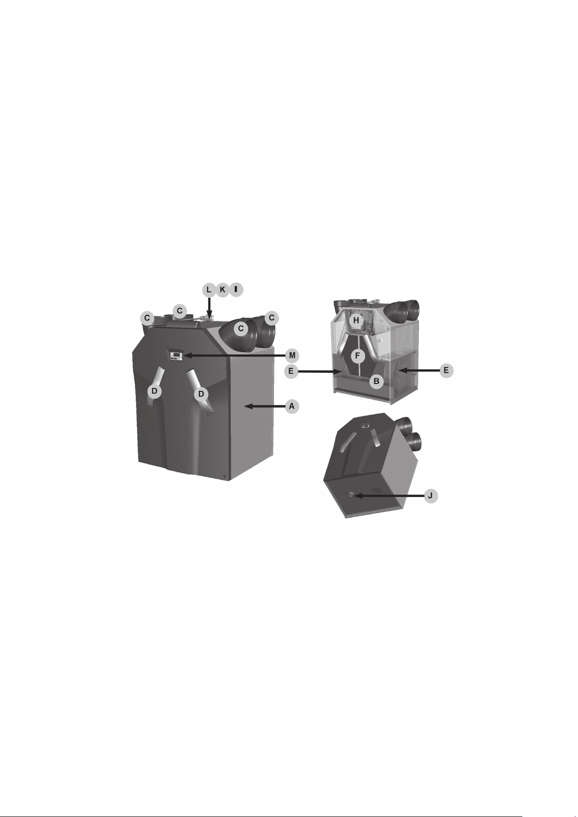
2.1 ComfoAir configuration .................................................................................................................................3
2.2 Technical specifications ................................................................................................................................4
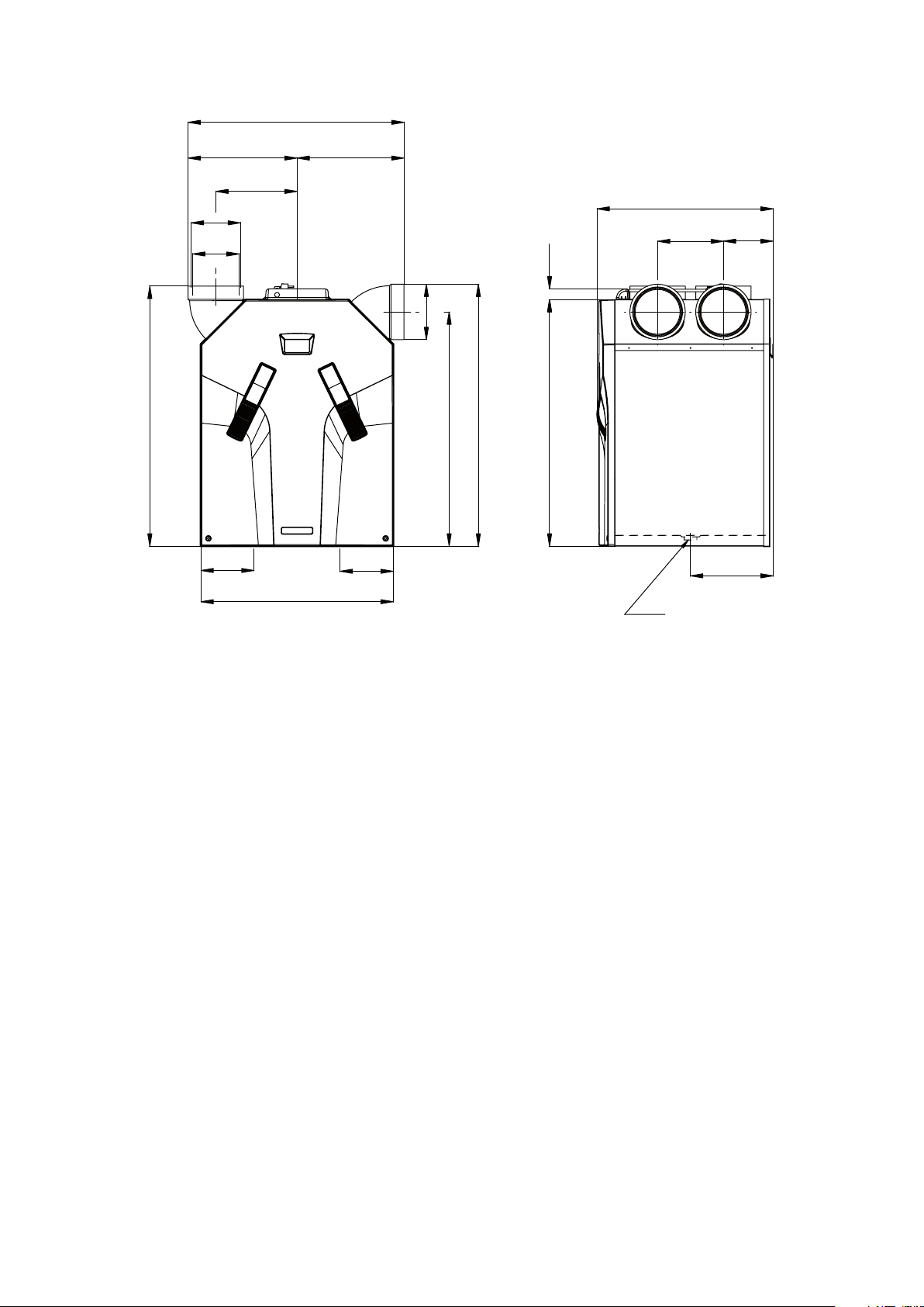
2.3 Dimension sketch ..........................................................................................................................................6
2.4 Installation conditions ...................................................................................................................................7
2.5 Installation of the ComfoAir ...........................................................................................................................7
2.5.1 Transport and unpacking ....................................................................................................................7
2.5.2 Checking the delivery..........................................................................................................................7
2.6 Mounting of the ComfoAir .............................................................................................................................7
2.6.1 Mounting on the wall...........................................................................................................................7
2.6.2 Connection of the air ducts.................................................................................................................8
2.6.3 Connection of the condensation drain ................................................................................................8
2.7 Commissioning the ComfoAir ........................................................................................................................9
2.7.1Display on the unit .................................................................................................................................9
2.7.2 P menus for the user......................................................................................................................... 10
2.7.3 P menus for the installer ...................................................................................................................12
2.8 Programming air specifications ...................................................................................................................15
2.9 Maintenance by the installer........................................................................................................................16
2.9.1 Inspecting and cleaning the heat exchanger.....................................................................................16
2.9.2 Inspecting and cleaning the fans ...................................................................................................... 17
2.9.3 Inspecting and cleaning the preheater element filter......................................................................... 17
2.10 Malfunctions................................................................................................................................................18
2.10.1 Malfunction alerts on digital operating devices.................................................................................18
2.10.2 3-position switches with malfunction indicator .................................................................................18
2.10.3 What to do in the event of a malfunction / Trouble shooting ............................................................. 19
2.10.4 Malfunctions (or problems) without alarms ......................................................................................25
2.11 Service parts ...............................................................................................................................................26
2.12 Wiring diagram: ComfoAir 350 Basic – LEFT-HAND version........................................................................27
2.13 Wiring diagram: ComfoAir 350 Basic – RIGHT-HAND version .....................................................................28
2.14 EEC declaration of conformity ....................................................................................................................29

EN - 4

5 - EN
Preface
Carefully read this manual before use.
This manual provides all the information required
for safe and optimal installation and maintenance
of the ComfoAir 350 . It is also intended as a
reference for servicing, so that this can be carried
out in a responsible manner. The device is subject
to continuous development and improvement. As
a result, the ComfoAir 350 may slightly differ from
the descriptions.
NOTE
This manual has been compiled with
the utmost care. However, no rights can be
derived from it. In addition, we at all times
reserve the right to change the contents of
this manual, without prior notice.
1 Introduction
The device's name is ComfoAir 350 . In the
following it will be referred to as ComfoAir.
The ComfoAir is a balanced ventilation system with
heat recovery in order to create healthy, balanced
and energy-efficient ventilation in houses. The
ComfoAir has a CE marking on the identification
plate. The identification plate can be found on top
of the ComfoAir.
1.1 Warranty and liability
1.1.1 Guarantee conditions
The ComfoAir is covered by a manufacturer’s
warranty for a period of 24 months after fitting
up to a maximum of 30 months after the date
of manufacture. Warranty claims may only be
submitted for material faults and/or construction
faults arising during the warranty period. In the
case of a warranty claim, the ComfoAir must
not be dismantled without written permission
from the manufacturer. Spare parts are only
covered by guarantee, if they were supplied by
the manufacturer and have been installed by an
approved installer.
The warranty becomes invalid if:
■The guarantee period has elapsed;
■The device is used without filters;
■Parts are used that have not been supplied by
the manufacturer;
■Non-authorised changes or modifications have
been made to the unit.
1.1.2 Liability
The ComfoAir has been designed and manufactured
for use in “balanced ventilation systems”. Any
other use is deemed unintended use and can lead
to damage to the ComfoAir or personal injury, for
which the manufacturer cannot be held liable.
The manufacturer is not liable for any damage
originating from:
■Non-compliance with the safety, operating and
maintenance instructions in this manual;
■The use of components not supplied or
recommended by the manufacturer.
Responsibility for the use of such components
lies entirely with the installer;
■Normal wear and tear.

EN - 6
1.2 Safety
1.2.1Safety regulations
Always comply with safety regulations in
this manual. Non-compliance with the safety
regulations, warnings, notes and instructions in this
manual can cause personal injury or damage to the
ComfoAir.
■The ComfoAir may only be installed, connected,
rendered operational and maintained by an
appropriately approved installer, unless otherwise
indicated in this manual;
■Installation of the ComfoAir must be carried out in
accordance with the general and locally applicable
construction, safety and installation instructions
of the local council, electricity and water boards
or other agencies;
■Observe the safety regulations, warnings,
comments and instructions as prescribed in this
manual at all times;
■Keep this manual with the ComfoAir throughout
its life;
■Instructions with regard to cleaning or replacing
the filters of the intake and exhaust valves must
be carefully observed;
■The specifications stated in this document may
not be changed;
■Modifying the ComfoAir is not allowed;
■The ComfoAir is only suitable for connetion to
230V 50Hz mains;
■It is recommended to take out a maintenance
contract so that the device is checked on a regular
Basic. The supplier can provide a list of registered
installers nearby.
1.2.2 Safety provisions and measures
■The ComfoAir cannot be opened without using
tools;
■It should not be possible to touch the fans,
therefore ducting must be connected to the
ComfoAir at a minimum duct length of 900mm.
1.2.3 Pictograms used
The following pictograms are used in this manual:
Point of attention.
Risk of:
- damage to the device;
- performance of the device is compromised if
instructions are not observed carefully.
Risk of personal injury to the user or installer.

7 - EN
2 For the Installer
2.1 ComfoAir configuration
The standard ComfoAir configuration consists of:
■External casing (A) of coated sheeting;
■Interior (B) of high-quality, expanded polypropylene (E)PP;
■4 connections (C) for the air ducts;
■2 plate filters (D) for air purification. Filter classification: outside air G4, return air G4;
■2 energy-efficient DC motors (E) with high-efficient fan;
■HE (High efficient) heat exchanger (F);
■Control circuit board (H1) with connections for the fans, the bypass, the Preheater element, temperature
sensors (T1 to T4), the 3-position switch with or without malfunction indicator (optional) and the bathroom
switch (optional);
■Identification plate (I) detailing information on the ComfoAir (not visible);
■Condensation drain (J) to drain the condensation of the warm return air;
■Sticker (K) detailing the air connections (not visible);
■Cable for power supply with 230V 5 core connection (L);
■Display (M) to read data, and for programming procedures.

EN - 8
2.2 Technical specifications
ComfoAir 350 nL (normal air volumes)
Position Ventilation capacity Power
Low Setting 100 m3/h at 20 Pa 21 W
Medium Setting 150 m3/h at 65 Pa 44 W
High Setting 225 m3/h at 150 Pa 105 W
Maximum 325 m3/h at 235 Pa 243 W
Position Ventilation capacity Current
Low Setting 100 m3/h at 20 Pa 0.17 A
Medium Setting 150 m3/h at 65 Pa 0.35 A
High Setting 225 m3/h at 150 Pa 0.81 A
Maximum 325 m3/h at 235 Pa 1.77 A
Electricity
Power supply 230/50 V/Hz
Cos.phi 0,50 - 0,60
Connecting Power 1,59 kW
Maximum Power Pre-heater 1,35 kW
Leakage current <1mA
Supply fan noise level (at 0 m)
Position Ventilation capacity Sound power
Low Setting 100 m3/h at 20 Pa 49 dB(A)
Medium Setting 150 m3/h at 65 Pa 59 dB(A)
High Setting 225 m3/h at 150 Pa 70 dB(A)
Maximum 325 m3/h at 235 Pa 75 dB(A)
Exhaust fan noise level (at 0 m)
Position Ventilation capacity Sound power
Low Setting 100 m3/h at 20 Pa 43 dB(A)
Medium Setting 150 m3/h at 65 Pa 48 dB(A)
High Setting 225 m3/h at 150 Pa 55 dB(A)
Maximum 325 m3/h at 235 Pa 61 dB(A)

9 - EN
ComfoAir 350 HL (high air volumes)
Position Ventilation capacity Power
Low Setting 125 m3/h at 25 Pa 27 W
Medium Setting 225 m3/h at 150 Pa 105 W
High Setting 300 m3/h at 230 Pa 196 W
Maximum 325 m3/h at 235 Pa 243 W
Position Ventilation capacity Current
Low Setting 125 m3/h at 25 Pa 0.21 A
Medium Setting 225 m3/h at 150 Pa 0.81 A
High Setting 300 m3/h at 230 Pa 1.42 A
Maximum 325 m3/h at 235 Pa 1.77 A
Electricity
Power supply 230/50 V/Hz
Cos.phi 0,50 - 0,60
Connecting Power 1,59 kW
Maximum Power Pre-heater 1,35 kW
Leakage current <1mA
Supply fan noise level (at 0 m)
Position Ventilation capacity Sound power
Low Setting 125 m3/h at 25 Pa 54 dB(A)
Medium Setting 225 m3/h at 150 Pa 67 dB(A)
High Setting 300 m3/h at 230 Pa 73 dB(A)
Maximum 325 m3/h at 235 Pa 75 dB(A)
Exhaust fan noise level (at 0 m)
Position Ventilation capacity Sound power
Low Setting 125 m3/h at 25 Pa 45 dB(A)
Medium Setting 225 m3/h at 150 Pa 55 dB(A)
High Setting 300 m3/h at 230 Pa 59 dB(A)
Maximum 325 m3/h at 235 Pa 61 dB(A)
General Specifications
HE Exchanger Material Polystyrene
Interior Material (E)PP / PA / PC
Thermal Yield 95%
Mass 39 kg

EN - 10
2.3 Dimension sketch
801 35
214
761
ø180
851
845
702
ø160
ø151
354 348
264
161
572
625
269
172 172
CONDENSATION DRAIN
LEFT-HAND VERSION
CONDENSA
TION DRAIN
RIGHT-HAND VERSION
CONDENSATION DRAIN ø32 (OUTSIDE)

11 - EN
2.4 Installation conditions
In order to determine whether the ComfoAir can be
installed in a certain area, the following aspects
must be taken into account:
■The ComfoAir must be installed according to
the general and locally applicable safety and
installation regulations of power and water
companies, as well as the instructions in this
manual.
■The system must be fitted to allow sufficient
room around the ComfoAir for the air
connections and supply and exhaust ducts as
well as for carrying out maintenance activities.
■The ComfoAir must be installed in a frost-free
space. The condensation must be drained off
frost-free, at a gradient and incorporate a 'U'
bend.
We do not recommend installing the
ComfoAir in areas with a higher average
humidity (such as bathroom or toilet). This
will prevent condensation on the outside
of the ComfoAir.
■The room must offer the following provisions:
- Air duct connections.
- 230V electrical connection.
- Provisions for the condensation drain.
- Wiring for an wired 3-position switch
(optional).
■A gap should be left near the doors in order to
ensure effective and draughtfree airflow in the
house. A gap under the inside doors must be
atleast 10mm.
If these openings are obstructed, due to
draught excluders or deep-pile carpet, the
airflow in the house will stagnate. As a result,
system performance will be compromised or
fail altogether.
2.5 Installation of the ComfoAir
2.5.1Transport and unpacking
Take the necessary precautions when transporting
and unpacking the ComfoAir.
Make sure the packing material is disposed
of in an environmentally friendly manner.
2.5.2 Checking the delivery
Contact your supplier immediately in case of
damage or an incomplete delivery. The delivery
must include:
■ComfoAir;
Check the identification plate to ensure that it is
the required type.
■4 x 45O connection bends;
■Mounting bracket;
■Documentation.
The ComfoAir is supplied in the following types:
Type
ComfoAir 350 Basic L
ComfoAir 350 Basic R
ComfoAir 350 Basic L RF
ComfoAir 350 Basic R RF
ComfoAir 350 Basic L VV
ComfoAir 350 Basic R VV
ComfoAir 350 Basic L VV RF
ComfoAir 350 Basic R VV RF
Meaning of the suffixes:
* L = Left version
* R = Right version
* RF = Contains the wireless control function by
default.
* VV = Contains a preheater element by default
2.6 Mounting of the ComfoAir
2.6.1Mounting on the wall
Mount the ComfoAir against a wall with a minimum
mass of 200 kg/m2. For other types of wall, we
recommend using the Zehnder mounting frame
on the floor (available as an optional extra). This
reduces contact noise as much as possible. The
ComfoAir does not require any space at the sides
for effective operation.
Do not mount the side of the ComfoAir
against the wall due to the risk of impact
sound.
1. Fasten the mounting bracket to the wall. Make
sure it is level and at least 878mm from the floor
(depending on the type of condensation drain
selected).
Leave a minimum space of 1m in front of the
ComfoAir for carrying out maintenance.
2. Hang the ComfoAir on the mounting bracket.
3. Mount the condensation drain under the
ComfoAir. The stated dimension of 235 mm is an
indication only, and is dependent on the type of
condensation drain selected.

EN - 12
2.6.2 Connection of the air ducts
The following aspects must be taken into account,
while installing the air ducts:
■Install the air exhaust duct so it drains in the
direction of the ComfoAir.
■Insulate the outside air supply and the air exhaust
duct between the roof/wall passage to render the
ComfoAir damp proof. This prevents the formation
of condensation on the outside of the ducts.
■To prevent unnecessary temperature loss in either
the summer or the winter, we recommend fitting
thermal and damp-proof insulation to the supply
ducts from the ComfoAir up to the supply valves.
■Install the air ducts with a minimum ø of 150 mm,
as little air resistance as possible and free from
air leakage.
■Install a silencer of at least 1m straight directly
onto the supply and return airconnections. For
relevant advice, please contact Zehnder.
■When using flexible channels only Zehnder
channel systems may be used. Any other flexible
channel will disturb the basic operating principle of
the balanced ventilation system.
■
We recommend that the ventilation system is fitted
with intake and exhaust valves made by Zehnder.
Outside air
Exhaust air
Supply air
Return air
ComfoAir 350 - LEFT
Return air
Supply air
Exhaust air
Outside air
ComfoAir 350 - RIGHT
2.6.3 Connection of the condensation
drain
ComfoAir 350 - LEFT
ComfoAir 350 - RIGHT
Standard heat exchanger
Warm exhaust air is cooled by the outside air in the
heat exchanger. This causes the moisture in the
indoor air to condense in the heat exchanger. The
condensation water created in the heat exchanger
is fed to a PVC condensation drain.
The connection for the condensation drain has an
external diameter of 32 mm. It is located underneath
the ComfoAir.
■Connect the condensation drain, via a pipe or
hose, to the water seal (siphon) of the domestic
waste-water system.
■Position the upper edge of the water seal at least
40 mm underneath the condensation drain of the
ComfoAir.
■Make sure that the outer end of the pipe or tube
exits is at least 60mm below the water level.
Ensure that the water seal connected to the
domestic waste-water system is always full
of water. This prevents the ComfoAir from
sucking in any leakage air.

13 - EN
Enthalpy exchanger
When the ComfoAir is fitted with an enthalpy
exchanger the humidity from the extracted air is
partly transferred to the fresh supply air. In this case
you delay the process of drying out the house in dry
winter months, additionally there is no condensate
that must be drained from the ComfoAir. Therefore
a condensation drain is not necessary with an
enthalpy exchanger.
Ensure that the condensation drain is sealed.
This prevents the ComfoAir from sucking in
any leakage air.
The condensation drain can be sealed with a
standard screw-cap.
2.7 Commissioning the ComfoAir
After installation, the ComfoAir must be
commissioned.
This can be done via the P menus on the digital
operating device. These P menus can be used to
enter various settings (ventilation programmes,
in particular) for the ComfoAir. An overview of the
available P menus is given below:
Menu Options
P1 Reading statuses (from menu P2)
P2 Setting time delays
P3 Setting and reading the ventilation levels
P4 Setting and reading the temperatures
P5 Setting additional programmes
P6 Setting additional programmes
P7 Reading and resetting malfunctions (and system
information)
P8 Setting the RF input and analogue
inp ut s (0 -10V )
P9 Reading statuses (from menu P5 and P6)
P menus P1, P2 and P9 can be accessed by the
user, mainly to read statuses and set time delays.
The remaining P menus P3 to P8 are intended
solely for the installer.
The ComfoAir's bypass valve will not work for
the first 4 minutes after a power cut unless
the programme mode is activated.
2.7.1 Display on the unit
The ComfoAir can be operated and commissioned
by means of a display. The display is a digital
operating device which is mounted on the
ComfoAir.
select menu up
OK down
supply off supply on
(led green) (led green)
comfort temperature
Shown in display
Ventilation setting absent
Ventilation setting low
Ventilation setting medium
Ventilation setting high
Menu symbol
Malfunction code (flashes)
Bypass
Access to the menus
Sequence Press Display Description
1MENU P2 Time delay
2q + q
(3 seconds)
P3 Press the buttons
simultaneously.
3 q P4 Temperatures
4 q P5 Settings
5 q P6 Settings
6 q P7 Malfunction / Reset /
Self-test
7 q P8 0 - 10V Inputs
8 q P9 Status
Example
Setting the MEDIUM POSITION of the supply fan to
40%.
Sequence Press Display Description
1MENU P2 Time delay
2q + q
(3 seconds)
P3 Press the buttons
simultaneously.
3OK P30 Exhaust fan
Position A
4q (6x) P36 Select P36
5OK 50 Current setting
6q (10 x
or press
continuously)
40 Select 40
7OK P35 Value is 40
8MENU P3
9MENU 1Fan setting
Some P menus (such as P1 and P9) can only
be read.
Leaving Reading menu
■At action point 6 press "MENU" (instead of "OK").
The display can not be used for setting the
ventilation positions of the ComfoAir. The
arrowkeys are only for setting the additional
programmes.
OK
MENU
·
·
·
OK
MENU
·
·
·
OK
MENU
·
·
·
OK
MENU
·
·
·
OK
MENU
·
·
·
1
A
2
3
X X
X X
•
1
A
2
3
X X
X X
•
1
A
2
3
X X
X X
•
1
A
2
3
X X
X X
•
1
A
2
3
X X
X X
•
1
A
2
3
X X
X X
•
1
A
2
3
X X
X X
•

EN - 14
2.7.2P menus for the user
Menu P1 ¨Status of programmes
Status
Sub-menu Description Activated
P11 Is menu 21 currently active? Yes (1) / No (0)
P12 Is menu 22 currently active? Yes (1) / No (0)
P13 Is menu 23 currently active? Yes (1) / No (0)
P14 Is menu 24 currently active? Yes (1) / No (0)
P15 Is menu 25 currently active? Yes (1) / No (0)
P16 Is menu 26 currently active? Yes (1) / No (0)
Menu P2 ¨Setting time delays
Time delay values
Sub-menu Description Minimum Maximum General
Reset
P21
(Optional)
Note:
Only applies to systems fitted with a
corded switch and a second switch in
the bathroom.
Delay timer for the bathroom switch (to switch to high
position).
■'x' minutes after operating the bathroom switch, the
ComfoAir switches to the high setting.
- Low voltage input
0 Min. 15 Min. 0 Min.
P22
(Optional)
Note:
Only applies to systems fitted with a
corded switch and a second switch in
the bathroom.
Overrun timer for the bathroom switch (to switch to
normal position).
■'x' minutes after operating the bathroom switch, the
ComfoAir switches back to the normal setting.
- Low voltage input
0 Min. 120 Min. 30 Min.
P23
(Optional)
Note:
Only applies to systems fitted with a
hardwired 3-position switch.
Overrun timer for ventilation position 3 (using a wired
3-position switch).
■If ventilation setting 3 (high) is switched on briefly (<
3 sec), the ComfoAir will switch to the high setting
for 'x' minutes and then automatically returns to the
normal setting.
If any 3-position switch is operated during this lagging
time the ComfoAir will instantly revert to the ventilation
position as set at that time.
0 Min. 120 Min. 0 Min.
P24 Filter warning
■'x' weeks after cleaning the filters the "filter dirty"
alert will reappear.
10 weeks 26 weeks 16 weeks
P25
Note:
Only applies to systems fitted with an
RF switch.
Overrun timer for ventilation setting 3 (using " ").
■After pressing " " briefly (< 2 sec.), the ComfoAir
will switch to the high setting for ‘x’ minutes and then
automatically returns to the normal setting.
If any 3-position switch is operated during this lagging
time the ComfoAir will instantly revert to the ventilation
position as set at that time.
1 Min. 20 Min. 10 Min.
P26
Note:
Only applies to systems fitted with an
RF switch.
Overrun timer for ventilation setting 3 " using ".
■After pressing " " continuously (> 2 sec.), the
ComfoAir will switch to the high setting for ‘x’ minutes
and then automatically returns to the normal setting.
If any 3-position switch is operated during this lagging
time the ComfoAir will instantly revert to the ventilation
position as set at that time.
1 Min. 120 Min. 30 Min.
P27 N/A 0 Min. 120 Min. 30 Min.
Menu P9 ¨Status of programmes (from menu P5 and P6 additional programmes)
Status
Sub-menu Description Activated
P90 Open fire programme active? Yes (1) / No (0)
P91 Bypass Open? Yes (1) / No (0)
P94 Analogue input (0-10V) active? Yes (1) / No (0)
P95 Frost protection or Preheater active? Yes (1) / No (0)
P97 Enthalpy programme active? Yes (1) / No (0)

15 - EN
2.7.3 P menus for the installer
Menus with a line at minimum and maximum value are Reading menus.
Menu P3 ¨Setting ventilation programmes
Ventilation programme values
Submenu Description Minimum Maximum General
Reset
P30 N/A 0% or 15% 97% nL / HL
15% / 15%
P31 Setting the capacity (in %) of the
exhaust fan in low position.
16% 98% nL / HL
35% / 40%
P32 Setting the capacity (in %) of the
exhaust fan in medium position.
17% 99% nL / HL
50% / 70%
P33 Setting the capacity (in %) of the
exhaust fan to high position.
18% 100% nL / HL
70% / 90%
P34 N/A 0% or 15% 97% nL / HL
15% / 15%
P35 Setting the capacity (in %) of the
supply fan in low position.
16% 98% nL / HL
35% / 40%
P36 Setting the capacity (in %) of the
supply fan in medium position.
17% 99% nL / HL
50% / 70%
P37 Setting the capacity (in %) of the
supply fan in high position.
18% 100% nL / HL
70% / 90%
P38 Current capacity (in %) of the
exhaust fan.
- - Current %
P39 Current capacity (in %) of the
supply fan.
- - Current %
Menu P4 ¨Reading the temperatures
Temperature values
Submenu Description Minimum Maximum General
Reset
P41 Comfort temperature 12 oC28 oC20 oC
P45 Current value of T1
(= outside air temperature)
- - Current oC
P46 Current value of T2
(= supply air temperature)
- - Current oC
P47 Current value of T3
(= return air temperature)
- - Current oC
P48 Current value of T4
(= exhaust air temperature)
- - Current oC

EN - 16
Menu P5 ¨Setting additional programmes
Additional programme values
Submenu Description Minimum Maximum General
Reset
P50 Activation of the open fire programme. 0 (= No) 1 (= Yes) 0
P51 Confirming the presence of
a Preheater element
0 (= No) 1 (= Yes) 0
Only change if a preheater element is installed afterwards or a general reset is given.
P52 Setting the Preheater programme.
■0; Guaranteed protection.
■1; High protection.
■2; Nominal protection.
■3; Economy.
0 3 2
In gua r ante ed prot ect ion mo de the Preheater element is switched on soonest; this level offers the best guarantee of balanced
ventilation. Vice versa, in econo my mod e the Preheater element switches on at the last possible moment; balanced ventilation is
not guaranteed in this mode.
When commissioning the ComfoAir, the Preheater programme can usually be left at level 2: nom inal m ode (factory setting). In
areas with frequent cold spells in winter (frequent periods of -10°C or lower), level 1 should be selected: hi gh pr otecti on or even
level 0: guarant eed protec tion.
P54 Confirming the presence of a bypass. 0 (= No) 1 (= Yes) 1
The standard ComfoAir configuration includes a bypass. Therefore, leave the value at ‘1’.
P56 Setting the required air volume in the house.
■nL: ”normal air volume”.
■HL: "high air volume".
nL HL HL
Setting the air volume is the starting point for programming the air specifications and setting the fans.
P57 Setting the ComfoAir type.
■Li = ”Left-hand version”.
■Re = ”Right-hand version”.
Li Re Li
With delivery the ComfoAir is correctly pre-programmed at the factory.
After an general reset the pre-programming is lost and the setting must be reset.
The right setting is mentioned on the identification plate on top of the ComfoAir.
P58 n/a 0 1 0
P59 Confirming the presence of an enthalpy exchanger.
■0; Enthalpy exchanger not fitted
■1; Enthalpy exchanger with RH sensor.
■2; Enthalpy exchanger without RH sensor.
0 (= No) 2 (= Yes) 0
Only an enthalpy exchanger without RH sensor can be fitted.
Menu P6 ¨Setting additional programmes
Additional programme values
Submenu Description Minimum Maximum General
Reset
P60 Confirming the presence of a geothermal heat exchanger.
■0; Geothermal heat exchanger not fitted
■1; Geothermal heat exchanger fitted
■3; Geothermal heat exchanger unregulated.
0 (= No) 3 (= Yes) 0
Only an unregulated geothermal heat exchanger can be fitted.

17 - EN
Menu P7 ¨Reading malfunctions (and system information)
(Malfunction) information values
Submenu Description Minimum Maximum General
Reset
P70 Current software version. Version number of the software (without “v”)
P71 Most recent malfunction. Code in accordance with alarm and malfunction alert
P72 Malfunction before the most recent one Code in accordance with alarm and malfunction alert
P73 Malfunction before the most recent two Code in accordance with alarm and malfunction alert
P74 Resseting malfunction(s)
■Set value tot '1' and press "OK" on the display.
01
(= activate)
0
P75 General reset.
■Press "OK" on the display for at least 5 seconds to
carry out a general reset.
All original software settings are re-
stored following a general reset.
0 1
(= activate)
0
Note:
After a general reset, the ComfoAir will ask you to reset the “nL / HL” (see P56) and “Li / Re” (see P57)
settings.
Following a general reset, all settings and programmes need to be checked and set to the right value.
P76 Self-testing the ComfoAir 0 1
(= activate)
0
■The LED's on the display will start blinking.
■The ComfoAir will run at maximum Rotation Per Minute (RPM).
■The bypass valve will open and close.
■The preheater valve will open and close after the bypass has closed (If a preheater element is fitted).
P77 Resetting filter dirty counter 0 1
(= activate)
0
Note:
This resets the counter that triggers a dirty filter alert on the ComfoAir. This allows the filter to be cleaned or replaced before
the dirty filter alert appears.
Menu P8 ¨Setting the RF input and digital inputs (0-10V)
Analogue input values
Submenu Description Minimum Maximum General Reset
850 RF input 1 0= not fitted 1= fitted 0 1 0
851 0= controlling 1= programming (RF input 1) 0 1 0
852 set point RF input 1
(programming)
0 100 50
853 min. setting RF input 1 0 99 0
854 max. setting RF input 1 0 100 100
855 0=positive RF input 1 1=negative setting RF input 1 0 1 0
856 Read-out RF input 0 100 -

EN - 18
The default settings of the ComfoAir nL are:
Position low 35%
Position medium 50%
Position high 70%
The default settings of the ComfoAir HL are:
Position low 40%
Position medium 70%
Position high 90%
Follow this procedure to programme the ComfoAir
(after installation):
1. Set the ComfoAir in programming mode.
- Display: Press simultaneously for at least 3
seconds on " " and " " until “InR” appears
on the display.
In programming mode, the bypass and
Preheater element valves are always closed.
After 30 minutes, the ComfoAir automatically
terminates the programming mode.
2. Close all windows and outside doors.
3. Close all inside doors.
4. Check the presence of structural overflow
provisions.
The structural overflow provisions must be at
least 12 cm2 per l/s.
5. Check if both fans function in the three speed
settings.
6. Switch the ComfoAir to high speed.
7. Install all valves and set the valves according
to the settings given or as set in the reference
house.
If no data are known:
– Install the valves and open them as far as
possible.
– Measure the air volumes; starting with the
intake air and then the exhaust air.
– If the measured air volumes deviate from the
nominal air volumes by more than +/-10%,
and the majority of the deviations is positive,
ensure that all deviations are positive. If the
majority of all deviations is negative, ensure
that all deviations are negative. Ensure that
one supply valve and one exhaust continue to
be fully open.
8. Change the fan settings in P menus P30 to P37 of the
digital operating device.
– Select the lowest possible setting in order to
conserve energy.
– Ensure that the ratios between low, medium and
high remain equal.
Use the chart of the ComfoAir's air
specifications to set the fans.
9. In the event that the currently set air volumes still
deviate too much: Adjust the valves.
10. Check the entire installation again, after all
valves have been set.
11. Switch the ComfoAir (back) to ventilation
position 2.
2.8 Programming air specifications
After installation, the ComfoAir must be programmed.
This can be done using the air specifications of the ComfoAir above.

19 - EN
- Display: Press simultaneously for 3 seconds on
"" and " "until “InR” disappears of the
display.
2.9 Maintenance by the installer
The following maintenance must be carry out by the
installer:
■Inspecting and (if necessary) cleaning the heat
exchanger;
■Inspecting and (if necessary) cleaning the fans;
■Inspecting and (if necessary) cleaning the
preheater element filter (If a preheater element is
fitted).
A concise explanation of these maintenance
activities is given in the paragraphs below.
Check the condensation drain once every 2
years.
Failure to carry out (periodic) maintenance
on the ComfoAir ultimately compromises the
performance of the ventilation system.
2.9.1Inspecting and cleaning the heat
exchanger
Check the heat exchanger once every 2 years.
1. Disconnect the power (A) from the ComfoAir.
2. Remove the handles (B) from the ComfoAir;
3. Remove the filters from the ComfoAir.
4. Release the front panel by unscrewing the screws
(C).
5. Slide the front panel upwards and remove the
front panel from the ComfoAir.
C
B
A
6. Release the cover panel by unscrewing the screws
(D).
7. Remove the cover panel.
When reassembling the front cover, the lower
section must first be inserted behind the
raised edge to ensure a good seal.
D
ComfoAir – Left-hand version
8. Pull the strap (E) to remove the heat exchanger
and the leakage tray (F).
9. Remove the bypass duct (G) in the left-hand
version of the ComfoAir.
E
F
G
ComfoAir – Right-hand version
8. Remove the bypass duct (G) in the right-hand
version of the ComfoAir.
9. Pull the strap (E) to remove the heat exchanger
and the leakage tray (F).
E
F
G
10. Remove the heat exchanger from the leakage
tray (F).
The heat exchanger may contain some
residual water!
When reassembling the leakage tray the
openings in the leakage tray must be on the
side of the condensation drain.

EN - 20
11. Inspecting and if necessary clean the heat
exchanger.
- Use a soft brush to clean the lamellae.
- Use a vacuum cleaner or air gun (no high
pressure) to remove dirt and dust.
Always clean against the direction of the
airflow. This prevent dirt from getting stuck in
the heat exchanger.
Only standard exchanger with a green cover and
Enthalpy exchanger with a blue cover:
a. Submerge the heat exchanger several times in hot
water (max. 40 °C).
b. Rinse the heat exchanger with clean hot tap water
(max. 40 °C).
c. Clasp the heat exchanger between both hands (on
the coloured side surfaces) and shake the water
from the heat exchanger.
Only an enthalpy exchanger with a bleu cover
can be washed with water. When having an
Enthalpy exchanger with a white cover do
never wash it with water.
Do not use aggressive cleaning agents or
solvents.
If the fans or preheater element filter also
need maintenance do not re-install the heat
exchanger yet.
12. If no more maintenance is necessary install all
parts in reverse order, reconnect the power and
carry out the self-test in accordance with menu
P76.
Fasten the screws to a maximum of 1.5
Nm. This is roughly equal to setting 2 of an
average battery-powered drill.
2.9.2 Inspecting and cleaning the fans
Check the fans once every 2 years.
1. Remove the heat exchanger as instructed in the
maintenance chapter of the heat exchanger.
2. Remove the small plastic panel (H) in front of the
control circuit board panel by unscrewing the two
screws.
3. Release the connectors (K) and the earth wire on the
control circuit board panel and fully remove the cables
including the two grommets (K).
4. Remove the entire scroll casing by pressing the
click fasteners (L).
5. Remove the inflow nozzle by pressing the click
fasteners surrounding the scroll casing.
6. Inspecting and if necessary clean the fans.
- Use a soft brush to clean the fan impellers.
- Use a vacuum cleaner to remove dust.
L
K
H
Do not damage the fan impellers or
temperature sensor.
If the preheater element filter also need
maintenance do not re-install the heat
exchanger yet.
7. If no more maintenance is necessary install all
parts in reverse order, reconnect the power and
carry out the self-test in accordance with menu
P76.
Fasten the screws to a maximum of 1.5 Nm.
This is roughly equal to setting 2 of an average
battery-powered drill.
2.9.3 Inspecting and cleaning the
preheater element filter
Clean the filter of the Preheater (if fitted)
once every 4 years.
1. Remove the heat exchanger as instructed in the
maintenance chapter of the heat exchanger.
2. Remove the small plastic panel (I) in front of the
control circuit board panel by unscrewing the two
screws.
3. Release the connectors (J) and the earth wire on
the control circuit board panel and fully remove
the cables including the two grommets (K).
4. Remove the cable (P) from the control circuit
board panel.
5. Remove the base (Q) of the Preheater element.
– The base is fitted in the electronic carriage with
four snap connections. Two snap connections
are located at the front (visible) and two at the
back (not visible).
6. Inspecting and if necessary clean the preheater
element filter.
- Clean the filter with a brush.
- Remove any deposit using a damp cloth.
7. Install all parts in reverse order.
8. Reconnect the power to the ComfoAir.
Other manuals for ComfoAir 350
2
Table of contents
Other Zehnder Rittling Air Conditioner manuals