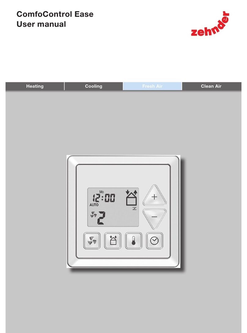
Zehnder Rittling ComfoControl Ease User guide

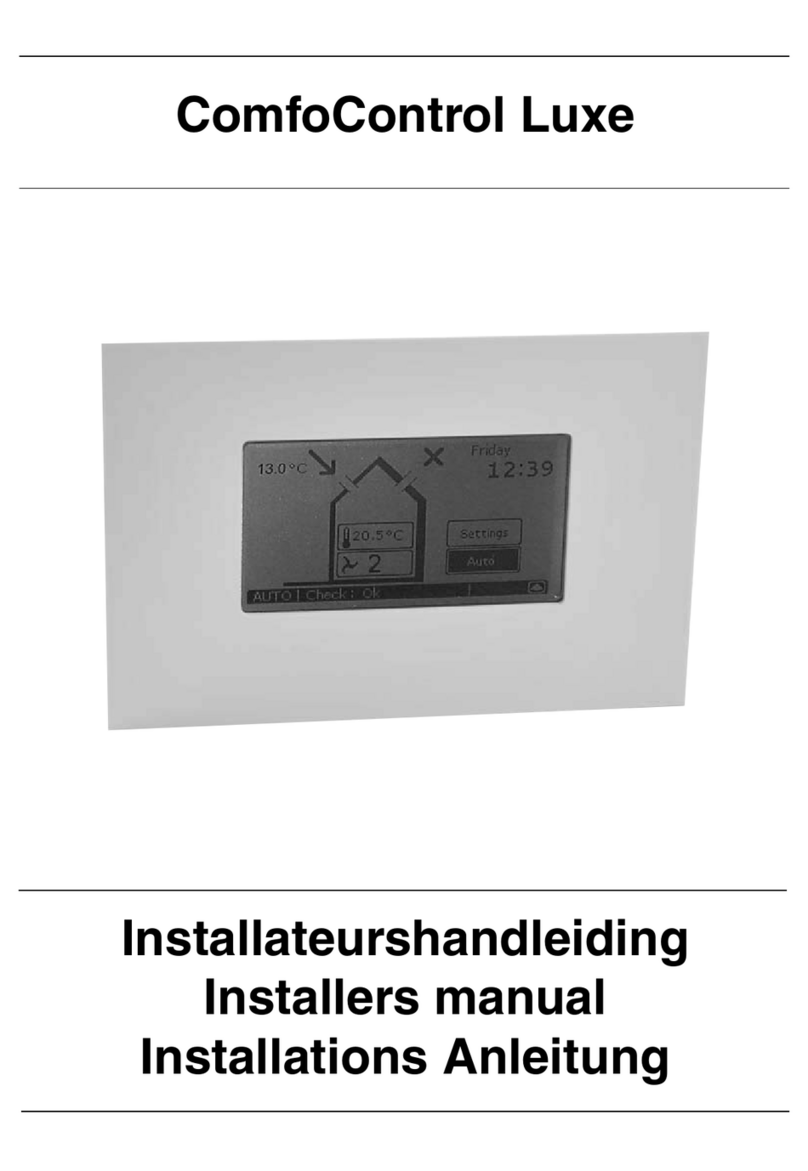
ComfoControl Ease
Installer manual
Cooling Fresh Air Clean AirHeating

2 - EN
All rights reserved.
This documentation has been compiled with the utmost care. The publisher cannot be
held liable for any damage caused as a result of missing or incorrect information in this
manual.

2 - EN EN - 3
Table of contents
Foreword
1. Introduction and Safety .................................................................................... 4
2. Checking the delivery ....................................................................................... 5
3. Installation conditions ...................................................................................... 5
4. The System ........................................................................................................ 6
4.1 Wall mounting ........................................................................................... 6
4.2 Cabling ....................................................................................................... 6
5. Commissioning .................................................................................................. 7
5.1 Use of the ComfoControl Ease .................................................................. 7
5.2 P menus .................................................................................................. 15
6. Maintenance .................................................................................................... 24
7. Malfunctions .................................................................................................... 24
8. Warranty and liability ...................................................................................... 26

4 - EN
Foreword
Read this manual carefully before
use.
This manual provides all the information
required for safe and optimal installation,
operation and maintenance of the
ComfoControl Ease. The device is
subject to continuous development
and improvement. There is therefore a
possibility that the ComfoControl Ease
differs slightly from the descriptions
given.
Applicable pictograms
The following pictograms are used in this
manual:
Point to watch.
Risk of:
- damage to the system;
- system performance is
compromised if instructions are
not observed carefully.
Questions
Please contact Zehnder with any
questions you might have on +1 603 422
6700 or via email at
info@zehnderamerica.com.
You can find more information on Zehnder
at: www.zehnderamerica.com.
1. Introduction
What is the purpose of this control
unit?
The ComfoControl Ease, referred to
further as CC Ease, enables users
to easily and comfortably operate a
balanced ventilation system with heat
recovery. The CC Ease is usually mounted
on the living room wall. It displays all
important information about the ventila-
tion system, referred to further as
ComfoAir, being operated. This means it
is not necessary to access the ComfoAir
unit itself to check that everything is
functioning properly.
The ComfoAir installer manual covers
in greater detail ventilation issues and
how the ComfoAir works. A copy of this
manual can be obtained from Zehnder.
Safety instructions
Always comply with safety regulations
in this manual. If the safety regulations,
warnings, comments and instructions
are not complied with, this can lead to
personal injury or damage to the
CC Ease.
■The CC Ease may only be fitted,
connected and commissioned by an
appropriately approved installer;
■Installation of the CC Ease must
be carried out in accordance with
the general and locally applicable
construction, safety and installation
instructions of the local council and
electricity company;
■Store the manual in the vicinity of the
CC Ease for its entire working life.

4 - EN EN - 5
2. Checking the delivery
Checking the delivery
Contact your supplier immediately in case
of damage or an incomplete delivery. The
delivery must include:
■CC Ease front section with PCB and
connector;
■CC Ease casing with PCB and
connector;
■Documentation.
Transport and unpacking
Take care when transporting and
unpacking the CC Ease.
Make sure the packing material is
disposed of in an environmentally
friendly manner.
3. Installation conditions
In order to determine whether the
CC Ease can be installed in a certain
area, the following aspects must be taken
into account:
■The CC Ease must be mounted at least
5 feet (1.5m) above the floor in a living
area and be easily accessible for the
user;
■The following facilities must be available
in the living area concerned:
- Flush-fit casing for the CC Ease.
- 12V DC power supply from the
ComfoAir.
- Rx/Tx communication cable from the
ComfoAir;
■The cable for connecting the CC Ease
must comply with the following minimal
requirements:
- Cable type: 2-conductor
shielded twisted pair 4 x 22 AWG
(4x0.34mm2).
- Cable length: 131 feet (40m)
maximum.

6 - EN
4. The System
4.1. Wall mounting
The CC Ease can be mounted in a
standard wall-mounted or flush-fit casing.
Wall-mounted casings in the same
colour as the CC Ease are available from
Zehnder.
Dimension sketch
2.36"
2"
1.22"
2.36"
2"
1.22"
Mounting instructions
To ensure the CC Ease front section can
be mounted correctly, the connector
in the casing of the CC Ease must be
located at the bottom.
.
When mounting the front section,
the connector must be plugged
into the PCB in the wall-mounted
casing.
4.2. Cabling
When connecting or
disconnecting the CC Ease,
the ComfoAir must first be fully
disconnected from its power
supply. This prevents current
being supplied to the CC Ease
unit’s input/output system.
The CC Ease should always be
crosslinked (Rx to Tx) with a
2-conductor shielded twisted
pair 4 x 22 AWG (4x0.34mm2) of
up to 131 feet (40m).
CC Ease ComfoAir
The ComfoAir installer manual indicates
the connection point on the side of the
ComfoAir.

6 - EN EN - 7
5. Commissioning
5.1 Use of the ComfoControl Ease
The overview below summarizes the information that will be displayed on the CC Ease.
Time and date
Actual ventilation setting
Ventilation programme
(AUTO) or manual
ventilation (MANUAL)
Signal to replace
internal (I) or external (E)
filter
Supply air
or exhaust air
ON or OFF
bypass activated
Comfort temperature or
temporary high setting,
analogue programme active
The CC Ease has a number of buttons to operate the ComfoAir and to enter the settings.
These buttons are illustrated below.
This button switches to the highest ventilation setting.
- Press once Boost setting ON.
- Press twice Boost setting OFF.
This button allows you to switch between supply/exhaust.
- Press once SUPPLY OFF (and EXHAUST ON).
- Press twice EXHAUST OFF (and SUPPLY ON).
- Press 3 times SUPPLY and EXHAUST both ON.
This button allows you to display or set the comfort temperature.
- Press for less than 2 seconds READ.
- Press for longer than 2 seconds SET.
This button allows you to adjust two settings.
- Press for less than 2 seconds Programme ventilation setting (AUTO / MANUAL).
- Press for longer than 2 seconds Set date and time.
These buttons allow you to adjust various settings:
- In P menu or comfort temperature screen Set values.
- In main screen enter ventilation setting (A, 1, 2, 3).
While the open fire programme is
activated the supply and exhaust
fan cannot be manually switched
off.
Not all CC Ease operating
functions are supported by each
ventilation system.

8 - EN
The CC Ease allows the following
functions to be programmed and
displayed:
■Reading and setting the day and time;
■Reading and setting the comfort
temperature;
■Reading and setting the ventilation
volume;
■Activating the temporary high setting;
■Switching the supply and exhaust fan
on/off (optional);
■Setting a personal ventilation
programme;
■Setting additional ventilation
programmes/options in the P menus.
A concise explanation of the above listing
is given in the paragraphs below.
After 30 seconds, the CC Ease
will return to the main menu
automatically.
> 2 sec. Current day
ashing
Select day
Current hour
ashing
Current minute
ashing
Select hour
Select
minute
Time set
> 2 sec. = fast-set
> 2 sec. = fast-set
Reading and setting the comfort temperature

8 - EN EN - 9
Reading and setting the comfort temperature
< 2 sec. View
comfort temp.
Main
screen
Comforttemperatuur aflezen en instellen
The comfort temperature can be set to
the required indoor temperature. Based
on this temperature, the ComfoAir will
then automatically switch to free cooling
using the bypass if required.
It is best to set the comfort
temperature to the same
temperature as the room
thermostat (of the central heating
system).
> 2 sec. Change
comfort temp.
Save & Main
screen
Reading and setting the ventilation
volume
The actual ventilation level, e.g. “2”, will
always be displayed on the CC Ease.
The ComfoAir regulates the required
ventilation levels automatically in
accordance with a preset ventilation
programme. During automatic ventilation
mode “AUTO” will be displayed on the
CC Ease.
Besides showing the programmed
ventilation setting, the CC Ease also
displays whether a temporary control
system (such as a CO2sensor or a
bathroom switch) is overriding the
ventilation setting.
In the event a required ventilation setting
is being overridden by a time delay
function (such as the bathroom switch
deactivation delay), a “t” is displayed in
the bottom right-hand corner of the
CC Ease.

10 - EN
In the event a required ventilation setting
is being overridden by a signal from a
sensor (such as a CO2sensor), an “A” is
displayed in the bottom right-hand corner
of the CC Ease.
Setting the ventilation levels
The ventilation level can also be set
manually by setting this higher or lower.
A total of 4 ventilation volumes/levels can
be set. These are:
■Setting A Absent.
- Use when house is
unoccupied;
At level A, the house is ventilated
using the minimum prescribed
ventilation volume.
The ComfoAir will switch to the
highest ventilation position set in
the house unless overruled by an
automated software programme.
■Setting 1 Low.
- Use for low ventilation
levels;
■Setting 2 Medium.
- Use if you require normal
ventilation;
■Setting 3 High.
- Use this position during
cooking, showering
and when additional
ventilation is needed;
■Timer Temporary high setting
- Use this position during
cooking, showering and
when extra ventilation is
briefly required.
< 2 sec.
< 2 sec.
or
AUTO setting /
MANUAL
setting
MANUAL
setting &
higher/lower

10 - EN EN - 11
Temporarily activating high setting
> 2 sec. Start Temporary
high setting
(P27)
Once the programmed time delay is
complete, the ComfoAir automatically
switches back to the former ventilation
setting.
The timer of the temporary high
setting can be switched off early
by pressing , or .

12 - EN
Switching supply and exhaust fan on/
off (optional)
While the open fire programme is
activated, the supply and exhaust
fan cannot be manually switched
off.
Bear in mind that switching off
the supply or exhaust fan will
temporarily immobilize your
dwelling’s balanced ventilation
system.
Supply fan switched off
Exhaust fan switched off
Supply and exhaust fans switched on
< 2 sec. Switch
supply/exhaust
fan on/o

12 - EN EN - 13
Setting ventilation programme
> 2 sec.
+
“Sa” flashes Select day
ventilation
profile stage
flashes
Hour
flashes
ventilation
profile stage
moment (1-8)
Select
hour
> 2 sec. = fast-set
Minute
flashes Select
minute
Ventilation
setting flashes
Select
ventilation
setting
Save + Sort
Define
new setting AUTO mode?
Day options are:
- Separate days
- Sa/Su
- Mo/Tu/We/Th/Fri
- Sa/Su/Mo/Tu/We/Th/Fri
"d" = delete
> 2 sec. = fast-set
Yes
Selecting factory reset will reload the default ventilation programme
(setting 2).

14 - EN
Resetting malfunctions
Reset error
messages
or filter dirty
Main Screen
Save
value
> 2 sec.
> 2 sec.
+
Start programme
mode
(InR)
User
P menu
(P1, P2, P9)
Select P menu
End
programme
mode
Installer
P menu
(P1-P9)
Select P submenu
Select value
+
> 2 sec.
> 2 sec.
- P1 & P9 submenus
cannot be changed.
- To perform a factory reset
in P75, press and hold
for 5 seconds.
> 2 sec. = fast-set
> 2 sec.
+
Programme mode
Using P menus

14 - EN EN - 15
5.2 P menus
Not all functions are supported by every
ComfoAir.
This might result in certain P menus not
being visible. It is also possible that some
changes you enter appear to have no
effect.
The ComfoAir installer manual states
which functions are supported. This
manual will also mention the effects of the
different functions.
P menus for the user.
Menu P1 Status of programmes
Status
Sub-menu Description Activated
P10 Is menu 20 currently active? Yes (1) / No (0)
P11 Is menu 21 currently active? Yes (1) / No (0)
P12 Is menu 22 currently active? Yes (1) / No (0)
P13 Is menu 23 currently active? Yes (1) / No (0)
P14 Is menu 24 currently active? Yes (1) / No (0)
P15 Is menu 25 currently active? Yes (1) / No (0)
P16 Is menu 26 currently active? Yes (1) / No (0)
P19 Is menu 29 currently active? Yes (1) / No (0)
Menu P2 Setting time delays
Time delay values
Sub-menu Description Minimum Maximum Factory reset
P20 n/a 0 Min. 180 Min. 0 Min.
P21
(Optional)
Note:
Only applies to systems
fitted with a corded
switch and a second
switch in the bathroom.
Activation delay for the bathroom
switch (to switch to high setting).
■“x” minutes after operating the
bathroom switch, the ComfoAir
switches to the high setting.
- Low voltage input
0 Min. 15 Min. 0 Min.
P22
(Optional)
Note:
Only applies to systems
fitted with a corded
switch and a second
switch in the bathroom.
Deactivation delay for the bathroom
switch (to switch to normal setting).
■“x” minutes after operating the
bathroom switch, the ComfoAir
switches to the normal setting.
- Low voltage input
0 Min. 120 Min. 30 Min.
P23 n/a 0 Min. 120 Min. 0 Min.

16 - EN
Time delay values
Sub-menu Description Minimum Maximum Factory reset
P24 Filter warning
■Here the user can indicate when the
“filter dirty” alert must appear.
10 weeks 26 weeks 16 weeks
P25 n/a 1 Min. 20 Min. 10 Min.
P26 n/a 1 Min. 120 Min. 30 Min.
P27 Time for the temporary high setting.
■After pressing and holding (>2 sec.)
, the ComfoAir runs at the high
setting for “x” minutes and then
switches back automatically to the
normal ventilation setting.
If a switch is operated during the
time delay mode, then the ComfoAir
switches immediately to the selected
ventilation setting.
0 Min. 120 Min. 30 Min.
P29 n/a 1% 99% 10%

16 - EN EN - 17
Menu P9 Status of programmes (from menus P5 and P6: additional programmes)
Status
Sub-menu Description Factory reset
P90 Open fire programme active? Yes (1) / No (0)
P91 Bypass Open? Yes (1) / No (0)
P92 n/a Yes (1) / No (0)
P93 Post-heater on? Yes (1) / No (0)
P94 Analogue ports (0-10V) active? Yes (1) / No (0)
P95 Frost protection on? Yes (1) / No (0)
P96 n/a Yes (1) / No (0)
P97 Enthalpy programme on? Yes (1) / No (0)

18 - EN
P menus for installer.
Menus without minimum and maximum values are read-only menus.
Menu P3 Setting ventilation programmes
Ventilation programme values
Sub-menu Description Minimum Maximum Factory reset
P30 Setting the capacity (in %) of the exhaust fan in
absent setting.
0% or
15%
97% nL / HL
15% / 15%
P31 Setting the capacity (in %) of the exhaust fan in low
setting.
16% 98% nL / HL
35% / 40%
P32 Setting the capacity (in %) of the exhaust fan in
normal setting.
17% 99% nL / HL
50% / 70%
P33 Setting the capacity (in %) of the exhaust fan in high
setting.
18% 100% nL / HL
70% / 90%
P34 Setting the capacity (in %) of the supply fan in absent
setting.
0% or
15%
97% nL / HL
15% / 15%
P35 Setting the capacity (in %) of the supply fan in low
setting.
16% 98% nL / HL
35% / 40%
P36 Setting the capacity (in %) of the supply fan in normal
setting.
17% 99% nL / HL
50% / 70%
P37 Setting the capacity (in %) of the supply fan in high
setting.
18% 100% nL / HL
70% / 90%
P38 Current capacity (in %) of the exhaust fan. - - Current %
P39 Current capacity (in %) of the supply fan. - - Current %
Menu P4 Reading temperatures
Temperature values
Sub-menu Description Minimum Maximum Factory reset
P40
(Optional)
Current value of TAH
(= Temperature of the Post-heater)
- - Current ˚ C
P41 Comfort temperature 12 ˚C 28 ˚C 20 ˚C
P44 n/a - - Current ˚C
P45 Current value of T1
(= Outside air temperature)
- - Current ˚C
P46 Current value of T2
(= Supply air temperature)
- - Current ˚C
P47 Current value of T3
(= Stale air temperature)
- - Current ˚C
P48 Current value of T4
(= Exhaust air temperature)
- - Current ˚C
P49 n/a - - Current ˚C
All temperatures are in degrees Celsius (°C). In the back of this document you
can find an conversion table. (°F = °C × 1.8 + 32)

18 - EN EN - 19
Menu P5 Setting additional programmes
Additional programme values
Sub-menu Description Minimum Maximum Factory reset
P50 Activation of the
open fire programme.
0 (= No) 1 (= Yes) 0
P51 n/a 0 (= No) 1 (= Yes) 0
P52 n/a 0 3 2
P53 n/a 0 (= No) 1 (= Yes) 0
P54 Confirming the presence of a bypass. 0 (= No) 1 (= Yes) 1
The standard ComfoAir configuration includes a bypass.
Leave the value at “1”.
P55
(Optional)
Confirming the presence of a Post-heater.
■0; Post-heater not fitted.
■1; Post-heater fitted.
■2; Post-heater is fitted and is regulated by a Pulse.
Width Modulation (PWM) signal.
0 (= No) 1 (= Yes) 0
P56 Setting the required
air volume in the house.
■nL: “normal air volume”.
■HL: “high air volume”.
nL HL HL
Note:
Setting the air volume is the starting point for programming the air specifications and setting the
fans.
P57 Setting the ComfoAir type.
■Li = “Left-hand version”.
■Re = “Right-hand version”.
Li Re Li
Note:
The ComfoAir is correctly preprogrammed at the factory.
This setting is lost during a factory reset and will then have to be reprogrammed.
The correct setting can be found on the ComfoAir's identification plate.
P58 Enter controller priorities.
■0; In the AUTO mode the signals of the analogue
(0-10V) ports are included when defining the high
setting.
■1; In the AUTO mode the signals of the analogue
(0-10V) ports are ignored when defining the high
setting.
0 1 0
Note:
In the MANUAL mode all signals are always included when defining the high setting.
P59
(Optional)
Confirming the presence of an enthalpy exchanger.
■0; Enthalpy exchanger fitted
■1; Enthalpy exchanger with RH sensor.
■2; Enthalpy exchanger without RH sensor.
0 (= No) 2 (= Yes) 0
If an enthalpy exchanger without a sensor is selected, then the protection programme will
not be activated and malfunction alerts EA1 & EA2 will never occur.

20 - EN
P6 Setting additional programmes (Optional)
Additional programme values
Sub-menu Description Minimum Maximum Factory reset
P60 n/a 0 (= No) 3 (= Yes) 0
P61 n/a 0% 99% 0%
P62 n/a 0ºC 15ºC 7ºC
P63 n/a 10ºC 25ºC 23ºC
P64
(Optional)
Tah (= temperature of the Post-heater), required 5ºC 40ºC 18ºC
Note:
The Post-heater will be deactivated once the set temperature has been reached.
All temperatures are in degrees Celsius (°C). In the back of this document
you can find an conversion table. (°F = °C × 1.8 + 32)
Menu P7 Reading malfunctions (and system information)
(Malfunction) information values
Sub-menu Description Minimum Maximum Factory
reset
P70 Current software version. Version number of the software
(without “v”)
P71 Most recent malfunction. Code in accordance with alarm
and malfunction alert
P72 Second most recent malfunction Code in accordance with alarm
and malfunction alert
P73 Third most recent malfunction Code in accordance with alarm
and malfunction alert
P74 Resetting a malfunction
■Set the value to “1” and press
01(= activate) 0
P75 Factory reset
■Set the value to “1” and press for at least 5
seconds.
All original software settings are restored following a
factory reset.
01(= activate) 0
Note:
After a general reset, the ComfoAir will ask you to reset the “nL / HL” (see P56) and “Li / Re”
(see P57) settings.
After a general reset, all settings and programmes must be checked and set to the correct
values where necessary.
Other manuals for ComfoControl Ease
1
Table of contents
Other Zehnder Rittling Thermostat manuals
Popular Thermostat manuals by other brands

Celect
Celect DRF3 instruction manual

Drayton
Drayton Combi-Stat RTS8 Installation instructions and instructions for use

Honeywell Home
Honeywell Home RTH7600 user manual

Trueway
Trueway Touch PAD TX1000ML220-V2E Applications manual

REMKO
REMKO ATR-4 operating instructions

meitav-tec
meitav-tec ETN24-PM-HP-SUPER-BL Owner's manual & technician settings

Computherm
Computherm Q7 operating instructions

Amana
Amana 2246002 Installation, operation & application guide

EQUATION
EQUATION TH30DP4 instruction manual

Honeywell
Honeywell TC500A Mounting instructions

Danfoss
Danfoss ECtemp 130 installation guide

Travis Industries
Travis Industries SKU 99300689 instructions