Zehnder Rittling ComfoControl Luxe User manual

ComfoControl Luxe
Handleiding
Manual
Manuel
Anleitung
comfosystems

Table of Contents
1 INTRODUCTION ........................................................................................................................................................................................................................................................................................................................ 1
1.1 Foreword .....................................................................................................................................................................................................................................................................................................................................................................................1
1.2 Warranty and liability .......................................................................................................................................................................................................................................................................................................................................... 1
1.2.1 General ................................................................................................................................................................................................................................................................................................................................................................. 1
1.2.2 Warranty conditions ........................................................................................................................................................................................................................................................................................................................ 1
1.2.3 Liability .....................................................................................................................................................................................................................................................................................................................................................................1
1.3 Safety instructions .................................................................................................................................................................................................................................................................................................................................................. 1
1.3.1 Pictograms used ................................................................................................................................................................................................................................................................................................................................... 1
2 FOR THE USER ........................................................................................................................................................................................................................................................................................................................... 1
2.1 ComfoControl .................................................................................................................................................................................................................................................................................................................................................................... 2
2.2 Using ComfoControl ............................................................................................................................................................................................................................................................................................................................................ 2
2.2.1 Time and date settings ................................................................................................................................................................................................................................................................................................................. 2
2.2.2 Comfort temperature settings .......................................................................................................................................................................................................................................................................................... 3
2.2.3 Ventilation volume settings .................................................................................................................................................................................................................................................................................................... 3
2.2.4 Switching extractor hood on/off ................................................................................................................................................................................................................................................................................... 4
2.2.5 Switching supply and exhaust fan on/off ....................................................................................................................................................................................................................................................... 4
2.2.6 Ventilation programme settings ..................................................................................................................................................................................................................................................................................... 5
2.2.7 Temperature programme settings .............................................................................................................................................................................................................................................................................. 6
2.2.8 Time delay settings ............................................................................................................................................................................................................................................................................................................................ 7
2.2.9 Temperature correction settings ................................................................................................................................................................................................................................................................................... 7
2.2.10 Screen settings ......................................................................................................................................................................................................................................................................................................................................... 8
2.2.11 Language settings ............................................................................................................................................................................................................................................................................................................................... 8
2.3 System data ......................................................................................................................................................................................................................................................................................................................................................................... 9
2.3.1 ComfoControl error messages ........................................................................................................................................................................................................................................................................................ 9
2.3.2 ComfoControl filter warning ................................................................................................................................................................................................................................................................................................. 9
2.3.3 Information about ComfoControl status .......................................................................................................................................................................................................................................................... 9
2.4 End of useful life......................................................................................................................................................................................................................................................................................................................................................... 10
3 FOR THE FITTER .................................................................................................................................................................................................................................................................................................................. 10
3.1 Installation conditions ..................................................................................................................................................................................................................................................................................................................................... 10
3.2 Installing ComfoControl .............................................................................................................................................................................................................................................................................................................................. 10
3.2.1 Transport and unpacking ..................................................................................................................................................................................................................................................................................................... 10
3.2.2 Checking the delivery ................................................................................................................................................................................................................................................................................................................ 10
3.3 Wall mounting ................................................................................................................................................................................................................................................................................................................................................................. 10
3.4 Connection to ventilation system ............................................................................................................................................................................................................................................................................................ 10
3.5 Connection to external temperature sensor ....................................................................................................................................................................................................................................................... 11
3.6 Commissioning ventilation and cooling system ......................................................................................................................................................................................................................................... 11
Contents III
English

Introduction 1
1 Introduction
This chapter provides general information on the ComfoControl.
1.1. Preface
In addition to this general chapter, this manual consists
of:
• A section for the user, and...
• A section for the fitter.
Read this manual carefully before use.
- User Chapters 1 and 2.
- Fitter Chapter 3.
This manual provides all the information required for the safe and
effective installation, set-up and operation of the ComfoControl. It
is also intended as a reference work for servicing, so that this can
be carried out in a responsible manner. The device is subject to
continuous development and improvement. There is therefore a
possibility that the ComfoControl differs slightly from the descrip-
tions given.
NOTE
This manual has been compiled with the greatest care. However, no rights
can be derived from it. J.E. StorkAir also retains all rights to change the
contents of this manual without prior notification.
1.2 Guarantee and liability
1.2.1 General
ComfoControl sales and warranty conditions for compa-
nies in the metals, plastics and technology industries were
deposited with the Clerk of the District Courts of the Hague
on the 19th of October 1998, under number 119/1998.
1.2.2 Warranty conditions
The ComfoControl is covered by a manufacturer's war-
ranty for a period of 24 months after fitting, up to a maxi-
mum of 30 months after the date of manufacture. Warranty
claims may only be submitted for material faults and/or
construction faults arising during the warranty period. In
the case of a warranty claim, the ComfoControl must not
be dismantled without written permission from the manu-
facturer. Spare parts are only covered by the warranty if
they were supplied by the manufacturer and have been
installed by an approved fitter.
The warranty becomes invalid if:
• the warranty period has elapsed;
• parts are used which were not supplied by the manu-
facturer;
• unauthorised alterations and/or modifications have
been made to the unit.
1.2.3 Liability
The ComfoControl has been designed and produced for
use in ventilation and cooling systems. Any other appli-
cation is considered inappropriate use and can result in
either damage to the ComfoControl or personal injury for
which the manufacturer cannot be held liable. The manu-
facturer is not liable for any damage derived from:
• Non-compliance with the safety, set-up and operating
instructions in this manual.
• The use of components not supplied or recommended
by the manufacturer.
• Responsibility for the use of such components lies en-
tirely with the fitter.
• Normal wear and tear.
1.3 Safety regulations
Always comply with safety regulations in this manual. Per-
sonal injury or damage to the ComfoControl can arise from
non-compliance with the safety regulations, warnings,
comments and instructions in this manual.
• Only registered fitters are permitted to assemble, fit,
commission and set up the ComfoControl, unless oth-
erwise indicated in this manual.
• The ComfoControl must be fitted in accordance with
the general and locally applicable construction, safety
and installation instructions of the local council, elec-
tricity and water boards or other agencies, such as the
relevant national home-building association.
• Always follow the safety regulations, warnings, com-
ments and instructions given in this manual.
• Store the manual in the vicinity of the ComfoControl
for its entire working life.
• Modifications may not be made to the ComfoControl.
1.3.1 Pictograms used
The following pictograms are used in this manual:
Point of attention.
Risk of:
- damage to the device, or
- personal injury to the user, or
- poor performance of the equipment if
the instructions are not followed carefully.
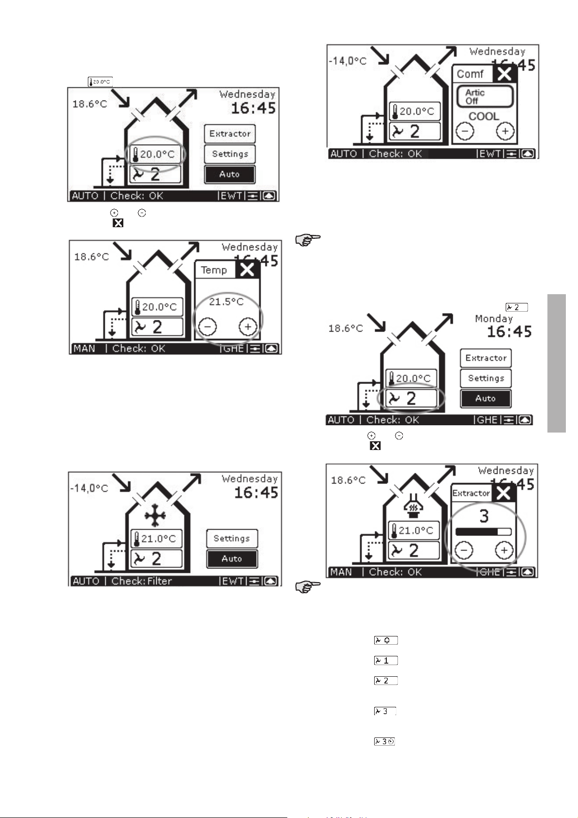
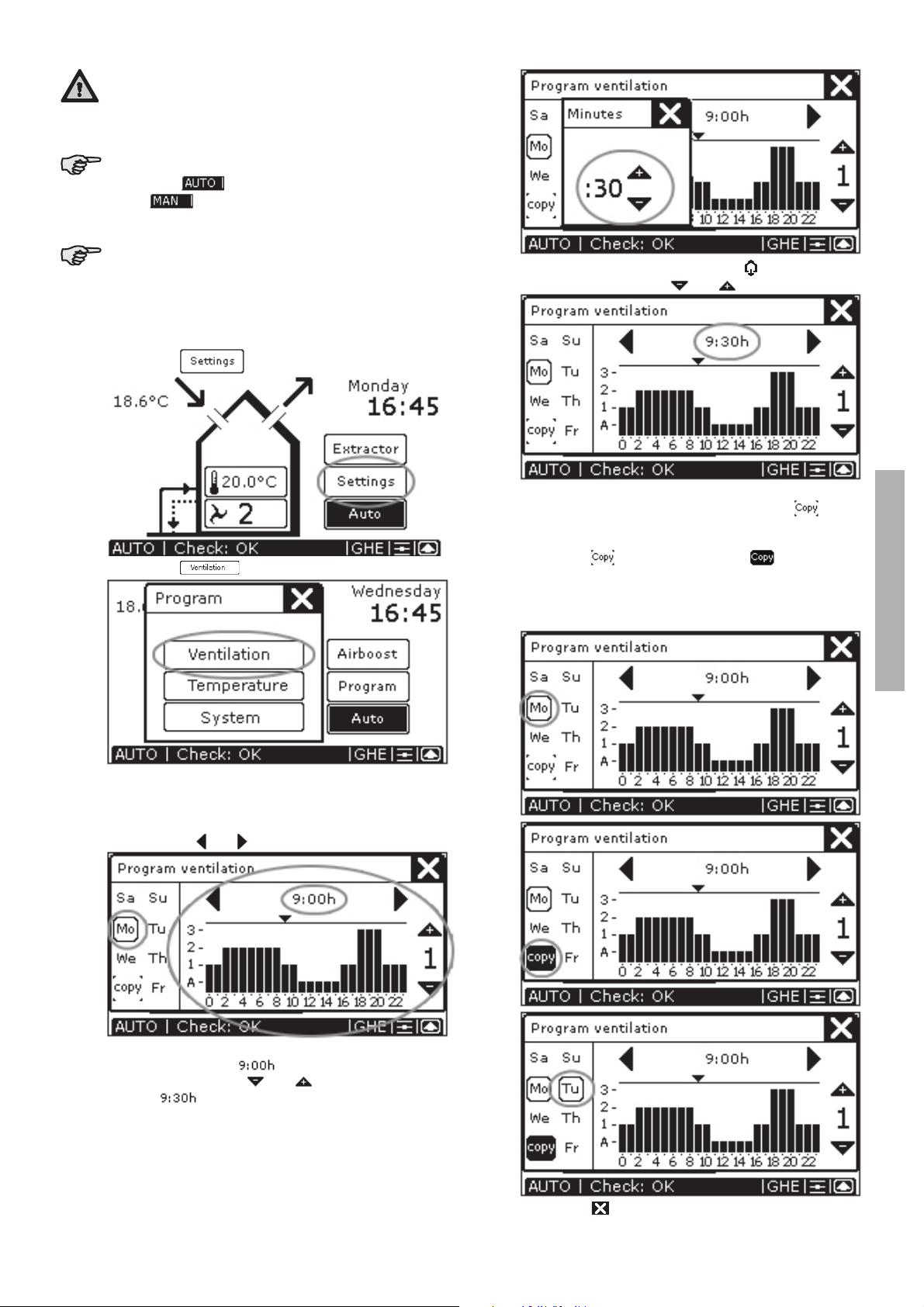
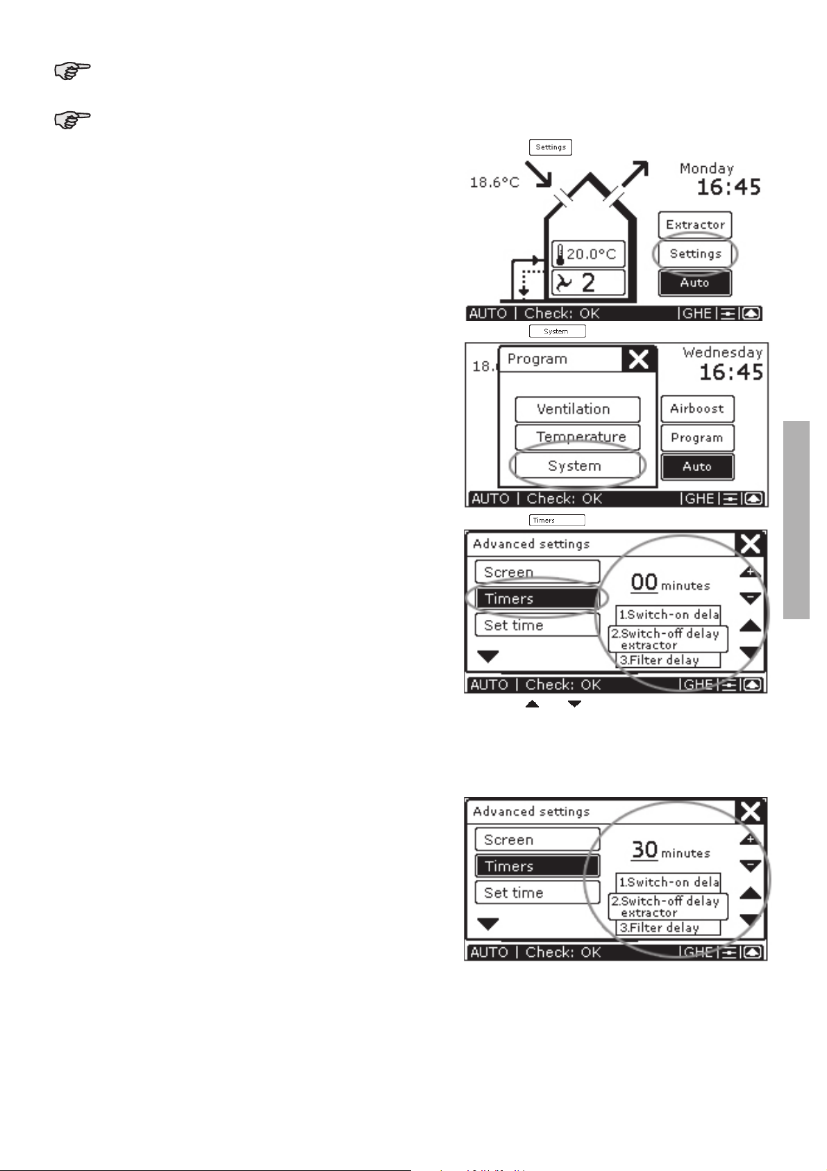
2 For the user
This chapter describes how to operate the ComfoControl.
Congratulations, you now own a ComfoControl,
the touch screen operating panel by J.E. StorkAir for
controlling your ventilation and/or cooling system.
We wish you every comfort.
English

2
2.2 Using ComfoControl
The ComfoControl is used for the following:
- Setting time and date.
- Setting the comfort temperature.
- Setting the ventilation volume.
- Switching the extractor hood on/off.
- Switching the supply and exhaust fan on/off.
If your ventilation system has a chimney cleaning
function, you will be unable to switch the supply
and exhaust fan on and off.
- Setting a personal ventilation programme.
- Setting a personal temperature programme.
- Setting a time delay for a number of ventilation set-
tings.
- Setting a temperature correction.
- Setting the screen.
- Setting the language.
A concise explanation of the above listing is given in the para-
graphs below.
2.2.1 Time and date settings
Use the ComfoControl to:
• Set the date and time.
The procedure is as follows:
1. Press "DAY AND TIME", here " ".
2. Press " " or " " to set the day.
3. Pressleft " " or " " to set the hour.
4. Pressright " " or " " to set the minutes.
5. Press " " to confirm the settings and return to the
main screen.
After 30 seconds, the ComfoControl will return to
the main menu automatically. Your settings have
now been saved.
2.1 ComfoControl
The ComfoControl regulates your ventilation and/or cooling system.
• The ComfoControl is mounted to the living room wall and communicates with your ventilation and/or cooling system.
The list below briefly explains what information the unit displays.
The ComfoControl display is a touch screen. All settings can be accessed, adjusted and confirmed simply by touching the screen.
OPEN or CLOSE air supply
Current outside temperature
Automatic or manual
ventilation activated
Actual temperature
(programmable using
MAN function)
OPEN or CLOSE
air exhaust
Go to SYSTEM STATUS
screen (for system data and
error messages)
Time and date
Cooling system,
reheater and/or
extractor hood activated
Switch extractor hood
ON or OFF
Go to SETTINGS screen
(for ventilation and
temperature settings)
Switch automatic
or manual ventilation
ON or OFF of
System status
and error messages
Actual ventilation setting
(programmable
using MAN function)
Heat Recovery
system activated
Bypass
OPEN [= ]
or bypass CLOSED [= ]
Heat Recovery
system active
If the function is not
surrounded by a ,
then it is not active
If the function is not
surrounded by a ,
then it is not active
English

3
2.2.2 Comfort temperature settings
The procedure is as follows:
1. Press "COMFORT TEMPERATURE", currently
"
".
2. Press " " or " " to set the comfort temperature.
3. Press " " to confirm the settings and return to the
main screen.
Comfo unit
The comfort temperature. Your Comfortunit-equipped
ventilation system tries continuously to maintain the tem-
perature of the room in which the operating panel is loca-
ted at the set comfort temperature.
It may have to open the bypass or activate the active coo-
ling to realize this objective.
• The comfort temperature can be set to between COOL
and WARM. Between these two parameters, you can
set it to 18–24°C.
• When COOL is selected, the system attempts to keep
the temperature as low as possible. If conditions al-
low, active cooling will be activated. Use this setting if
you wish to cool the dwelling considerably.
• If WARM is selected, then the active cooling will never
be activated and the bypass remains closed. Use this
setting when you turn the heating up.
• Your heat-recovery unit is fitted with a system that
detects whether it is summer or winter. In the sum-
mer, the active cooling can be activated, while this is
not desirable under normal winter conditions. All the
same, if you wish to use active cooling in the winter,
then set the temperature to COOL.
• Active cooling can be deactivated. In the screen in
which the comfort temperature can be entered, you
will see a button that can be set to either “Artic Auto”
or “Artic Off”. Select “Artic Off” if you do not wish to
use active cooling, even if your dwelling gets warmer
than the required comfort temperature.
After 30 seconds, the ComfoControl will return to
the main menu automatically. Your settings have
now been saved.
2.2.3 Ventilation volume settings
The procedure is as follows:
1. Press "VENTILATION SETTING", currently " ".
2. Press " " or " " to set the ventilation volume.
3. Press " " to confirm the settings and return to the
main screen.
After 30 seconds, the ComfoControl will return to
the main menu automatically. Your settings have
now been saved.
There are 4 ventilation volumes/settings. These are:
• Setting " " Absent.
- Use when absent.
• Setting " " Low setting
- Use for low ventilation levels.
• Setting " " Normal.
- Use for normal
ventilation levels.
• Setting " " High setting.
- Use for cooking, showering and if
extra ventilation is required.
• Setting " " High setting, with programmed
deactivation delay. See § 2.2.8.
English

4
- Use for cooking, showering and if
extra ventilation is required.
The ComfoControl will display "
" as stand-
ard during manual ventilation, and not " ".
If you wish to reactivate the automatic ventilation setting,
then:
• Press "AUTO" to return to the automatic ventilation
setting.
2.2.4 Switching extractor hood on/off
The procedure is as follows:
1. Press " " to activate the extractor hood.
2. Press " " or " " to set the ventilation volume for the
extractor hood.
3. Press " " to confirm the settings and return to the
main screen.
The extractor hood symbol (" ") then appears
on the ComfoControl display.
4. Press " " again to deactivate the extractor
hood.
Note!
If the extractor hood is fitted with a time-delay switch (see
§ 2.2.8 for more information about time delay), then it will
not switch off immediately, but will continue to run for the
programmed time period.
The extractor hood symbol (“ ”) disappears from
the ComfoControl display once the programmed
time delay has run its course.
Note!
If the extractor hood is fitted with a time-delay switch (see
§ 2.2.8 for more information about time delay), then the
time delay symbol (“ ”) will appear on the ComfoCon-
trol display in place of the ventilation volume buttons. The
extractor hood will be switched off after the programmed
number of minutes.
There is no ventilation volume setting
(“ “) displayed on the ComfoControl is when the
extractor hood is activated. Instead, the extractor hood
ventilation setting is displayed in the extractor hood sym-
bol. These are:
• “ ” for extractor hood ventilation setting 1.
• “ ” for extractor hood ventilation setting 2.
• “ ” for extractor hood ventilation setting 3.
If the extractor hood is running, the programmed
ventilation setting is displayed in the extractor
hood symbol (e.g. “ ”).
2.2.5 Switching the supply and exhaust fan on/off
The procedure is as follows:
1. Press “ « to switch off the supply fan.
2. Press “ « to switch off the exhaust fan.
Once the supply and exhaust fans have been de-
activated, “ ” is displayed on the ComfoControl
to indicate they are switched off.
3. Press “ ” by the supply fan symbol to reactivate the
supply fan.
4. Press “ ” by the exhaust fan symbol to reactivate
the exhaust fan.
Once the supply and exhaust fans have been
activated, both “ ” and “ ” are displayed on
the ComfoControl to indicate they have been
switched on again.
English

5
Bear in mind that switching off the supply or ex-
haust fan will temporarily immobilize your bal-
anced ventilation system.
Once the supply or exhaust fan has been deac-
tivated, “ ” will no longer be displayed,
but “ ” will appear on the ComfoControl
as standard.
If your ventilation system has a chimney cleaning
function, you will be unable to switch the supply
and exhaust fan on and off.
2.2.6 Setting the ventilation programme
The ventilation volume can be changed/set as follows:
1. Press “ ”.
2. Press “ ”.
3. Setting the ventilation programme.
– Select day: “Mo”, “Tu”, “We”, “Th”, “Fr”, “Sa”
or “Su”.
– Select hour, 00:00 to 23:00,
using “ ” or “ ”.
– If required, press the hour,
for example: “ ”, and then select the
minutes using “ ” or “ ”, for example:
“ ”.
– Select the ventilation setting, , 1, 2 or 3, for
each hour using “ ” or “ ”.
If you wish to copy the programmed ventilation setting to
the following (or any other) day, then use the “ ” func-
tion. This goes as follows:
- Select the day, for example: “Mo”.
- Press “ ”; which changes to “ ”.
- Select the day to which the ventilation setting is to
be copied, for example: “Tu”. “Tu” now has the same
ventilation setting as “Mo”.
4. Press “ “ to confirm the settings and return to the
English

6
main screen.
The programmed ventilation level only works in
the AUTO setting.
After 30 seconds, the ComfoControl will return to
the main menu automatically. Your settings have
now been saved.
2.2.7 Temperature programme settings
Use the ComfoControl to:
• Set a personal temperature programme.
The ComfoControl comes with default temperature set-
tings. If so required, you can change the standard tem-
perature programme to meet your personal temperature
requirements. Examples include weekday and weekend
programmes. The temperature settings can be changed/
set as follows:
1. Press “ ”.
2. Press “ ”.
3. Setting the temperature programme.
– Select day: “Mo”, “Tu”, “We”, “Th”, “Fr”, “Sa”
or “Su”.
– Select hour, 00:00 to 23:00, using “ ” or “ ”.
– If required, press the hour, for example: “ ”,
and then select the minutes using “ ” or “ ”, for
example: “ ”.
– Select the temperature setting (12 to 28 ˚C) for
each hour using “ ” or “ ”.
If you wish to copy the programmed temperature setting
to the following (or any other) day, then use the “ ”
function. This goes as follows:
– Select the day, for example: “Mo”.
– Press “ ”; which changes to “ ”.
– Select the day to which the temperature setting is to
be copied, for example: “Tu”. “Tu” now has the same
temperature setting as “Mo”.
4. Press “ “ to confirm the settings and return to the
main screen.
English

7
The programmed temperature level only works
in the AUTO setting.
After 30 seconds, the ComfoControl will return to
the main menu automatically. Your settings have
now been saved.
2.2.8 Time delay settings
Use the ComfoControl to:
• Programme a time delay for certain ventilation set-
tings.
The procedure is as follows:
1. Press “ ”.
2. Press “ ”.
3. Press “ ”.
4. Press “ ” or “ ” to choose between:
– Time delay for the bathroom off switch
Maximum 120 minutes.
– Time delay for the extractor hood off switch
Maximum 180 minutes.
– Delay the “FILTER DIRTY” message on the
ComfoControl Maximum 26 weeks.
English

8
5. Press “ ” or “ ” to set the number of minutes
(weeks) delay required.
6. Press “ ” to confirm the settings and return to the
main screen.
The minimum and maximum time delay for the
(ventilation) settings are preset in the software.
After 30 seconds, the ComfoControl will return to
the main menu automatically. Your settings have
now been saved.
2.2.9 Temperature correction settings
If the ComfoControl is used in conjunction with a heating
system thermostat, we recommended synchronizing the
temperature for both units on the display.
Use the ComfoControl to:
• Programme a temperature correction relative to the re-
corded temperature.
The procedure is as follows:
1. Press “ ”.
2. Press “ ”.
3. Press “ ” and then “ ”.
4. Press “ ” or “ ” to correct the ˚C setting.
5. Press “ ” to confirm the settings and return to the
main screen.
After 30 seconds, the ComfoControl will return to
the main menu automatically.
2.2.10 Screen settings
Use the ComfoControl to:
• Set the clarity and contrast of the touch screen.
The procedure is as follows:
1. Press “ ”.
2. Press “ ”.
English

9
3. For “BRIGHTNESS” press “
” or “ ” to adjust the clar-
ity.
4. For “CONTRAST”, press “ ” or “ ” to adjust the
contrast.
5. Press “ ” to confirm the settings and return to the
main screen.
After 30 seconds, the ComfoControl will return to
the main menu automatically. Your settings have
now been saved.
2.2.11 Language settings
Use the ComfoControl to:
• Select a language.
The procedure is as follows:
1. Press “ ”.
2. Press “ ”.
3. Press ” ”.
4. Press “ ” or “ ” to select the required language.
5. Press “ ” to confirm the settings and return to the
main screen.
After 30 seconds, the ComfoControl will return to
the main menu automatically. Your settings have
now been saved.
2.3 System data
Certain system information can be displayed on the Com-
foControl:
– Error messages.
– Warning to clean or replace the filters.
– Information on the status of your ventilation and/or
cooling system.
2.3.1 ComfoControl error messages
In the event of a malfunction, the ComfoControl will dis-
play the corresponding code.
The ComfoControl display will show an ‘A’ or an ‘E’, fol-
lowed by a number.
What to do in the event of a malfunction
In the event of a malfunction, reset as follows:
• Press “ ” to go to “SYSTEM STATUS”.
• Press “ ” to delete the error message, for ex-
ample “ERROR E2”.
Multiple malfunctions will be displayed as a list.
Multiple malfunctions will be displayed in the
“SYSTEM STATUS” screen. only “ERROR E2” is
currently displayed.
If the same malfunction returns repeatedly, please contact
the fitter.
• Make a note of which ventilation and/or cooling sys-
tem you have.
• Make a noteof the error code on the ComfoControl
display.
The system should not be unplugged, unless your ventila-
tion and/or cooling system must be taken out of service
due to a serious malfunction, or for filter cleaning/replace-
ment or any other compelling reasons. When the unit is
unplugged, the dwelling will no longer enjoy mechanical
ventilation, and this can lead to problems with damp and
mould. For this reason, please avoid switching off your
English

10
ventilation and/or cooling system for long periods.
2.3.2 ComfoControl filter warning
If the ventilation system’s filters require replacement (or
cleaning), then the “FILTERS – REPLACE FILTERS” warn-
ing appears on the ComfoControl display.
To replace (or clean) any filters, please refer to
your ventilation system’s user manual.
Once the ventilation system’s filters have been replaced
(or cleaned), then follow the steps below to delete the filter
warning from the ComfoControl display:
• Press “ ” to go to “SYSTEM STATUS”.
• Press “ ” to delete the “FILTERS– REPLACE FIL-
TERS” warning.
2.3.3 Information about ComfoControl status
In the absence of error message, you will see:
• “CHECK: OK” on the ComfoControl display.
Information on the status of your ventilation and/or cool-
ing system can then be accessed. This goes as follows:
• Press “ ” to go to “SYSTEM STATUS”.
The “SYSTEM STATUS” screen displays all the system
data on the ComfoControl.
• Press “ ” to return to the main screen.
2.4 End of useful life
Consult your supplier as to what you should do with the
ComfoControl at the end of its useful life. If the Comfo-
Control cannot be returned to the supplier, avoid dis-
posing of it with the industrial waste, and ask your local
council about the options for recycling the components
or processing the materials in an environmentally friendly
manner.
3 For the Fitter
This chapter describes how to fit the ComfoControl.
3.1 Installation conditions
In order to determine whether the ComfoControl can be
installed in a certain area, the following aspects must be
taken into account:
• The ComfoControl must be mounted 1.5 metres from
the floor.
• The ComfoControl must be fitted to allow sufficient air
to circulate. For example, not behind a cupboard, or in
a corner.
• The ComfoControl must not be located close to a heat
source, such as radiators, TVs, lamps, etc. Direct sun-
light must also be avoided.
• The ComfoControl must not be located close to a cold
source, such as cold-water pipes or unheated walls
(due to poorly heated areas on the other side of the
wall), etc.
• The following facilities must be available in the living
area concerned:
– Flush-fit casing for the ComfoControl.
– 12V DC power supply from the
ventilation system.
– A/B communication cable from the
ventilation system.
3.2. Installing ComfoControl
3.2.1 Transport and unpacking
• Take care when transporting and unpacking the Com-
foControl.
Make sure the packing material is disposed of in
an environmentally friendly manner.
3.2.2 Checking the delivery
Contact your supplier immediately in case of damage or
an incomplete delivery. The delivery includes:
• ComfoControl.
• Mounting bracket (fitted to the bottom of the Comfo-
Control).
• Connectors (fitted to the rear of the ComfoControl on
the PCB).
• User manual.
English

11
3.3 Wall mounting
• Mount the bracket on the wall.
The bracket has five mounting holes.
If required, the bracket can be fitted to the flush-
fit casing.
• Connect the ComfoControl to the ventilation system;
see § 3.4.
• Slide the ComfoControl onto the mounting bracket.
• Fasten the bottom of the ComfoControl with a screw.
3.4 Connection to
ventilation system
• Connect the 12V DC cable to the connector.
• Connect the A/B communication cable to the con-
nector.
The wiring diagram can be found at the rear of the Com-
foControl:
• Plug the connector into the 12V DC “POWER” fitting
on the PCB.
• Plug the connector into the RS 485 “COMM” fitting on
the PCB.
Open Comm Power Relay Relay
Temp.Sens
Therm RS 485 12V DC 1 2
* * A B - + * * * *
The cable specification is: 4 x 0.25 mm2protected
(twisted pair).
3.5 Connection to external
temperature sensor
• Connect the temperature sensor cable to the connec-
tor.
The wiring diagram can be found at the rear of the Com-
foControl:
• Plug the connector into the “TEMP.SENS” fitting on
the PCB.
• Fit both jumpers to the PCB at position 1:2 (left).
Jumpers Left: Temp. Senso
Jumpers Right: Relay 2
Open Comm Power Relay Relay
Temp.
Sens
Therm RS 485 12V DC 1 2
* * A B - + * * - +
The temperature sensor specification is: NTC 10
K(optional).
The external temperature sensor is optional. The indoor
temperature is usually monitored by an internal tempera-
ture sensor (in the ComfoControl). However, indoor tem-
perature can also be monitored using an external tem-
perature sensor. This may be because the ComfoControl
is to be fitted in a different location than the one to be
monitored, for example in the hall. It is also possible that
variables in the vicinity of the unit (e.g. wall temperature)
could affect temperature readings. An external tempera-
ture sensor connected to the PCB in the back of the Com-
foControl provides a solution to these problems.
3.6 Commissioning the ventilation
and cooling system
Once fitted, the ventilation and cooling system must be
commissioned.
This can be done via the P menus of the ComfoControl.
These P menus can be used to enter various settings (and
programmes) for the ventilation and cooling system. An
overview of the available P menus is given below:
For a list of available settings in the P (sub)menus,
please refer to the user manual for your ventila-
tion and/or cooling system.
Accessing P menus
1. Press “ ”.
2. Press “ ”.
English

12
3. Press “ ”; and then “ ”.
4. Press code “3520” to go to the “INSTALLATION
MENU”.
5. Press “ ” or “ ” to go to:
– The “INSTALL VENTILATION” menu, or …
– The “INSTALL ARTIC” menu.
6. Press “OK” to enter the selected menu.
The P menus are now accessible
If the Artic cooling system is not connected, the
“OK” will not appear on the screen, and the re-
lated P menus will not be available.
7. Using “ ” or “ ”, select the required P menu,
e.g. “P5 OPTIONS”.
8. Press “OK” to confirm the P menu selected.
9. Using “ ” or “ ” , select the required P sub-
menu, e.g. “P51 PRE HEATER”.
10. Press “OK” to confirm the P submenu selected.
Entering settings in P menus
The procedure is as follows:
11. Using “ ” or “ ”, select a value for the param-
eter.
12. Press “ ” to confirm the parameter’s new value.
English

13
13. If necessary, press “ ” again to return to the P
menus.
14. Repeat steps 7 to 13 to enter multiple parameters.
The minimum and maximum values for the avail-
able settings parameters are preset in the soft-
ware.
Returning to the main menu
The procedure is as follows:
15. Press “ ” to return to the “INSTALLATION MENU”.
16. Press “ ” again to return to the main screen.
After five minutes, the ComfoControl will return
automatically to the main screen.
Once parameters have been set in the P menus,
the ComfoControl returns almost immediately to
the main screen. However, this will take longer
after a system reset (see Menu P7), as the sys-
tem then has to reboot.
English
Other manuals for ComfoControl Luxe
2
Table of contents
Other Zehnder Rittling Thermostat manuals
Popular Thermostat manuals by other brands

Honeywell
Honeywell T6812A1000 installation guide

Danfoss
Danfoss FP975 user guide

Salus
Salus ERT20 Operating and mounting instructions

Horstmann
Horstmann HRT3 installation instructions

Dettson
Dettson R02P033 Installation instructions and homeowner's manual

Tantalus
Tantalus ST-1480 OPERATING AND INSTALLATION Manual