Zenitel Vingtor Stentofon FCDC3 Instruction sheet

Configuration Manual
Flowire Converter
FCDC3
A100K11958
TECHNICAL MANUAL

2A100K11958
FCDC3 Flowire Converter Conguration Manual
About this Document
Document Scope
This document provides a detailed guide to the system setup and conguration of the FCDC3 Flowire
Converter in creating IP networks using conventional telecom star-wired infrastructure (2-wire).
Relevant Products
Product Description Item Name Item No.
Flowire Converter, 24-48V DC FCDC3 1008080310
Power Supply 100-240VAC 24VDC 2A WAGO-787-1606 2990000063
Power Supply 100-240VAC 24VDC 4A WAGO-787-1616 2990000064
Power Supply 100-240VAC 48VDC 2A WAGO-787-1623 2990000065
Power Supply 100-240VAC 48VDC 5A WAGO-787-1633 2990000066
Turbine Extended Ex IP Intercom TFIX-1 1008123010
Turbine Extended Ex IP Intercom TFIX-2 1008123020
Turbine Extended Ex IP Intercom TFIX-3 1008123030
Turbine Extended Ex IP Intercom TFIX-4 1008123040
Exigo Access Panel Ex EAPFX-1 1023221511
Exigo Access Panel Ex EAPFX-6 1023221516
Publication Log
Ver. Date Author Status
1 5.3.2020 MR/HKL Published
Related Documentation
For further information, refer to the following documentation:
Doc. number Documentation
A100K11959 Flowire Guidelines for Exigo
A100K11957 Flowire Getting Started
A100K11960 Replacing Flowire Converter
A100K11xxx AutoCAD Dimension Drawing
A100K11499 Exigo & Turbine Ex Installation & Maintenance
Acronyms
Acronym Meaning
FCDC Flowire Converter Direct Current
Flowire Star
Conguration
A star conguration consisting of two or more Flowire devices, with a link to each other,
and one PSU.
NMK Network Management Key
PLC Power Line Communication. This is the basis of the Flowire technology for transporting
both power and signal on power cables or any other cable with at least two conductors.
PSU Power Supply Unit

3
FCDC3 Flowire Converter Conguration Manual
A100K11958
Contents
1 Product Description ............................................................................................................4
1.1 General Description .......................................................................................................4
1.2 Areas of Application .......................................................................................................5
1.2.1 Retrotting Older Intercom & Telephone Systems ......................................................5
1.2.2 Remote IP Intercom Locations in New Buildings ........................................................5
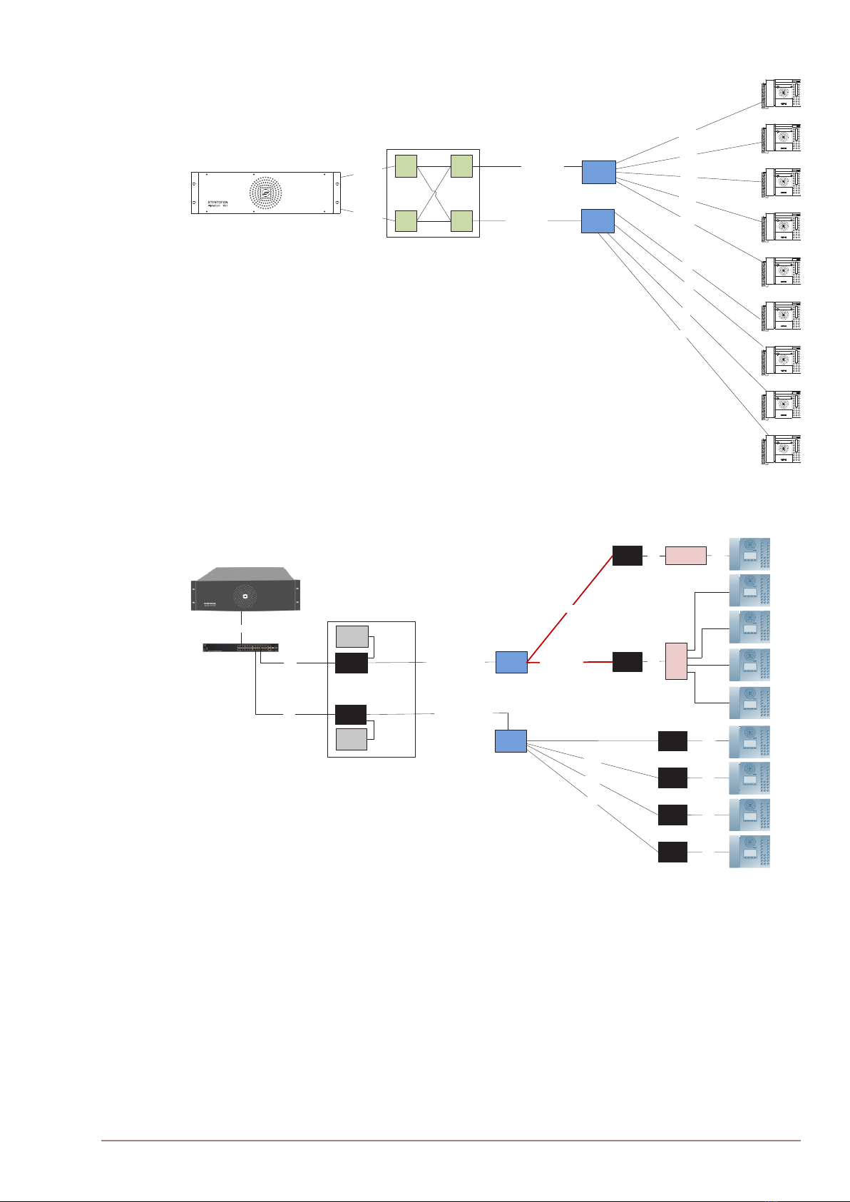
2 Upgrading Conventional Star-Wired Infrastructure .........................................................6
2.1 The Conventional System .............................................................................................6
2.2 Power on Conventional Infrastructure ...........................................................................7
2.3 Precaution & Limitations ................................................................................................7
2.4 Recommendations .........................................................................................................7
2.5 System Conguration with Central Powering of Remote Intercoms ..............................8
2.6 System Conguration with Local Powering of Remote Intercoms .................................9
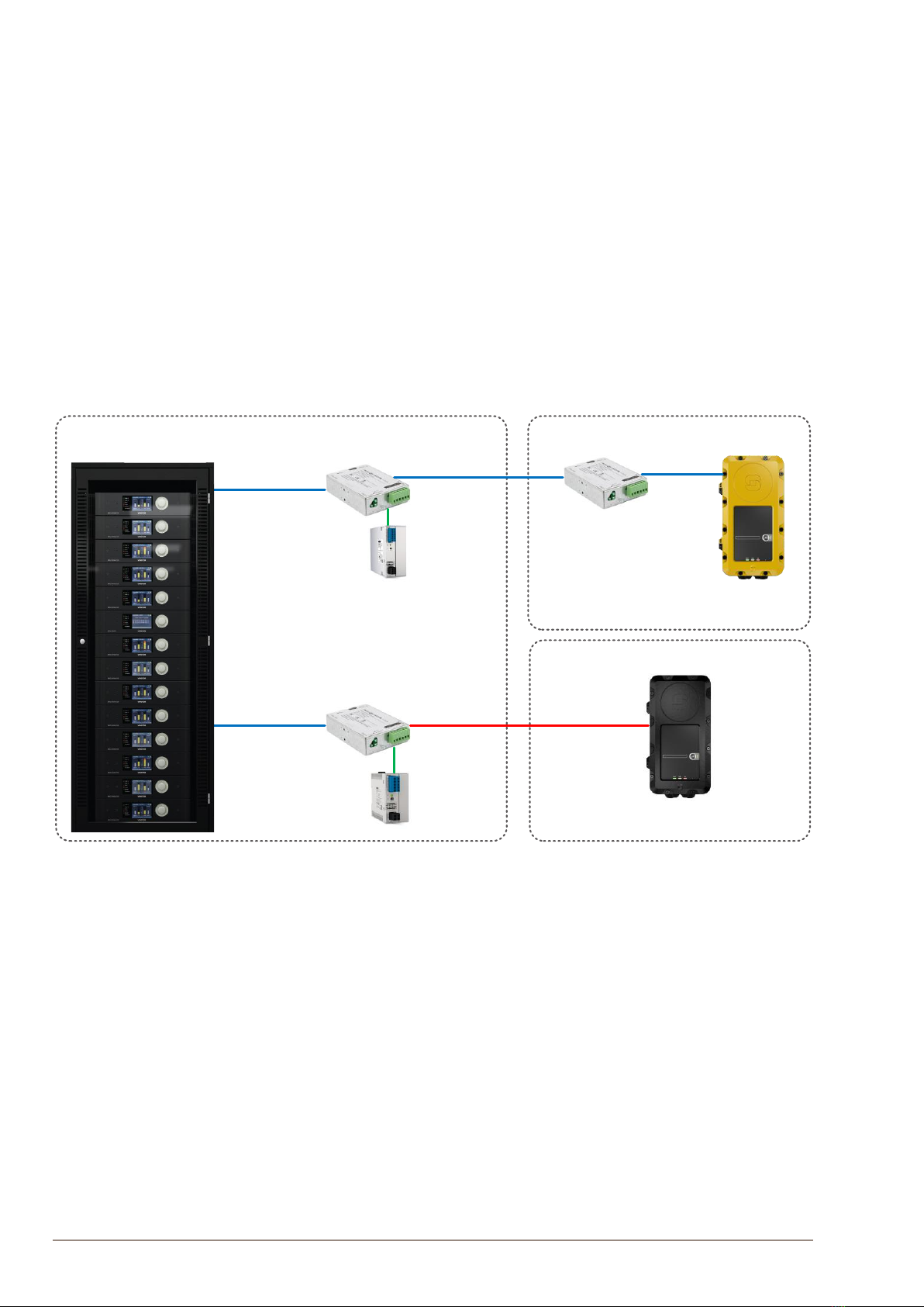
2.7 System Conguration with Industrial & Ex Devices .....................................................10
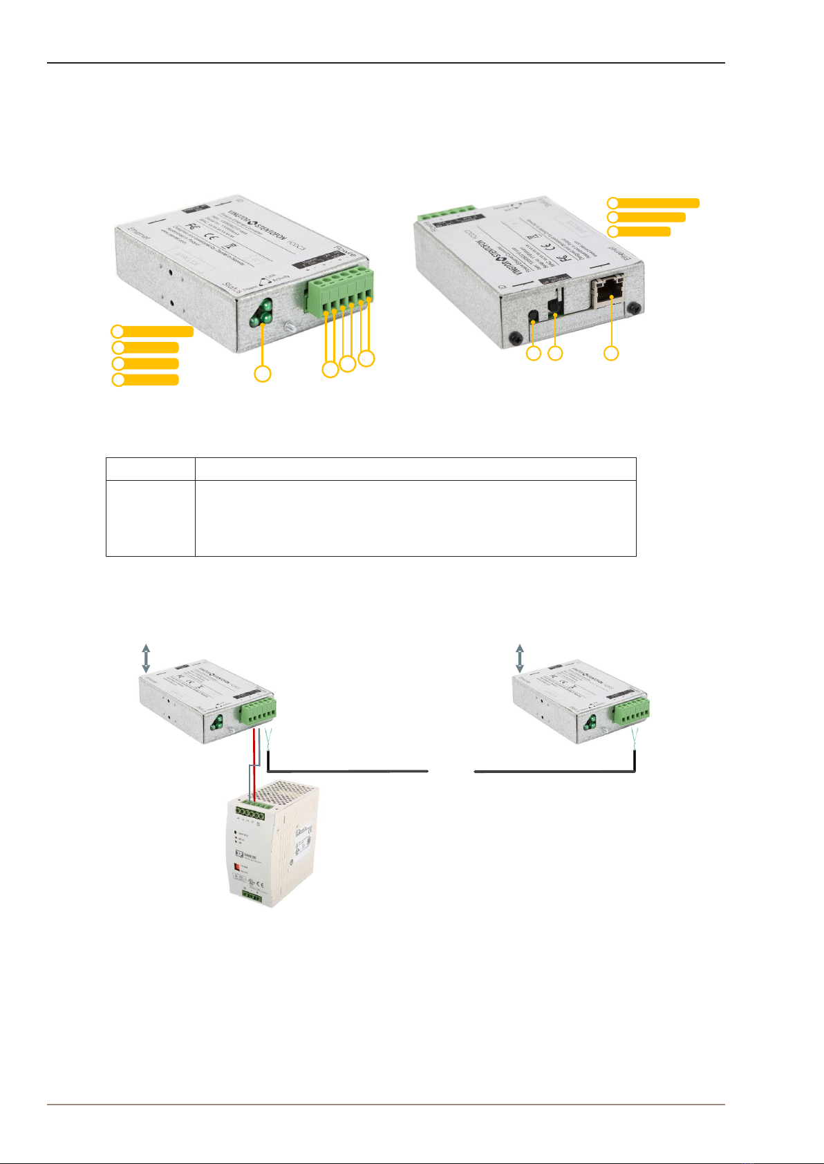
3 Connections & Indications ............................................................................................... 11
3.1 Flowire Connection ...................................................................................................... 11
3.2 Ethernet Connection .................................................................................................... 11
3.3 Indicator LEDs ............................................................................................................. 11
3.4 Password Reset Button ............................................................................................... 11
4 Mounting & Recommendations........................................................................................12
4.1 Mounting the Flowire Converter ..................................................................................12
4.2 Power Requirements ...................................................................................................13
5 Troubleshooting ................................................................................................................14
5.1 Power for Stable Connection at Remote Site ..............................................................14
5.2 Cables & Bandwidth ....................................................................................................14
5.3 System Log ..................................................................................................................14
A: Power Consumption & Distances for Typical Cables ....................................................17
B: AdvancedConguration...................................................................................................18
B.1 Setting a Static IP Address & Disabling DHCP ............................................................18
B.2 Network Management Key (NMK) Conguration ........................................................19
B.3 CCo Settings ...............................................................................................................20
C: Software Upgrade..............................................................................................................21
C.1 Upgrade via Web Interface on Flowire Device ............................................................21
D: Upgrade FCDC1/FCDC2, EAPFX, TFIX to Operate with FCDC3 ....................................22
Figures
Figure 1 FCDC3 Flowire Converter .......................................................................................................................... 4
Figure 2 FCDC3 PoE Enabled and FCDC3 PoE Disabled ....................................................................................... 4
Figure 3 Conventional star-wired infrastructure ........................................................................................................ 6
Figure 4 Conventional star infrastructure with multi-pair cables and junction boxes ................................................ 6
Figure 5 Flowire Upgraded conguration with central power distribution. ............................................................... 8
Figure 6 Conventional analog/digital system conguration....................................................................................... 9
Figure 7 Flowire Upgraded conguration with local power at remote locations ........................................................ 9
Figure 8 Cabling in Ex & Industrial Zones............................................................................................................... 10
Figure 9 FCDC3 Flowire Converter Dimensions ..................................................................................................... 12
Figure 10 DIN Mounting Clips ................................................................................................................................... 12

4A100K11958
FCDC3 Flowire Converter Conguration Manual
1 Product Description
1.1 General Description
The Flowire Converter enables Ethernet to run on the same two wires as power, providing simpler
cabling and opening up for longer cable hauls. The Flowire converter is also capable of powering the
Ethernet devices (Vingtor-Stentofon IP intercom stations) attached to it via spare pairs.
Power Input
PLC 1
PLC 22
3
4
234
1
Status Indicators1
2 3
Password Reset Button1
PoE On/Off Switch2
1
Ethernet Port3
Figure 1 FCDC3 Flowire Converter
Model Description
FCDC3 24-48 VDC Flowire Converter with power-forwarding (PoE, type 2)
capabilities. Forwards 48V from the power supply to the spare pairs
of the Ethernet port (not true PoE) if PoE-switch is in enable position.
Does not forward 48V to the spare pairs of the Ethernet port if PoE-
switch is in disable position
-
PSU
48VDC
Ethernet
2-wire
Ethernet
with power on spare pairs
FCDC3
FCDC3
+
Po E disabled PoE enabled
Figure 2 FCDC3 PoE Enabled and FCDC3 PoE Disabled
LIt is recommended to use FCDC3 with PoE enabled only when you need to power
the connected device via the spare pairs of the Ethernet port. In all other situations,
use the FCDC3 with PoE disabled.

5
FCDC3 Flowire Converter Conguration Manual
A100K11958
1.2 Areas of Application
The main areas of application for the Flowire Converter are:
● Retrotting older communication systems
● Providing Ethernet connectivity to remote locations in buildings
1.2.1 RetrottingOlderIntercom&TelephoneSystems
● Analog and digital intercom systems
● Analog and digital telephone systems
The above solutions typically use a conventional star-wired telecom infrastructure with 0.5 mm2 (20
AWG) single-pair twisted cables.
1.2.2 Remote IP Intercom Locations in New Buildings
In some new building projects, it is a challenge to provide Ethernet connectivity to remote locations
(beyond 100 meters from the main equipment room) for critical communication.
By implementing Flowire Converters, it is possible to upgrade these systems with IP products without
costly and time consuming re-cabling of CAT or ber cables.

6A100K11958
FCDC3 Flowire Converter Conguration Manual
2 Upgrading Conventional Star-Wired Infrastructure
2.1 The Conventional System
A conventional star-wired infrastructure supports analog and digital intercom and telephone systems.
These star-wired telecom infrastructures are typically used in both marine and onshore intercom
applications.
Figure 3 Conventional star-wired infrastructure
In this solution, you will have a centralized equipment rack with the following equipment:
● Telecom / Intercom Exchange
● Power Supply Unit
● Main Distribution Frame
The Main Distribution Frame connects the exchange to subscriber lines connected in a star structure.
Figure 4 Conventional star infrastructure with multi-pair cables and junction boxes
In order to simplify maintenance and reduce cabling costs, it is common to use multi-pair cables and
junction boxes in order to branch out to dierent locations.

7
FCDC3 Flowire Converter Conguration Manual
A100K11958
Conventional star-wired telecom infrastructures commonly use one twisted wire pair to each telecom
device. However, many systems, like AlphaCom, use two twisted pairs for each telecom device
2.2 Power on Conventional Infrastructure
In an analog and digital telecom/intercom system, it is usually a requirement to power the telephones/
intercoms from the central equipment rack, thus supplying the power over the subscriber line.
Typical maximum subscriber line distances for intercom systems are:
Wire cross section Distance
0.6 mm2 (19 AWG) 2.0 km
0.5 mm2 (20 AWG) 1.4 km
Table 1 AlphaCom Subscriber Line Distance
Wire cross section Distance
0.5 mm2(20 AWG) 0.8 km
Table 2 AsaCom Subscriber Line Distance
2.3 Precaution & Limitations
● The cable shields must be interconnected in junction boxes and grounded in the central device
only.
● Never use a cable run where the voltage drops below half of the PSU voltage.
● Do not connect more than 10 Flowire Converters on one Flowire star conguration.
● Powering of remote IP intercom stations through their Ethernet ports requires at least 40 VDC
at the remote site.
2.4 Recommendations
● Use twisted-pair shielded cables
● Unless the cables are shielded, you should avoid running wires from dierent Flowire star
congurations in the same cable ducts.
● Avoid multi-pair cables with connections to other systems.
● If you are using a multi-pair cable, but not all its pairs, connect more pairs between two Flowire
Converters to reduce voltage drop and increase bandwidth.
● In a central rack with two or more Flowire Converters in close proximity, use heat shrink with
grounding on unshielded areas of the cable to isolate the dierent Flowire star congurations
and avoid cross-talk.

8A100K11958
FCDC3 Flowire Converter Conguration Manual
2.5 SystemCongurationwithCentralPoweringofRemoteIntercoms
Figure 5 Flowire Upgraded conguration with central power distribution.
In the gure above, there are two Flowire star congurations, each with one central FCDC3 Flowire
Converter with PoE disabled and one central PSU (Power Supply Unit). FCDC3 with PoE enabled is
used to power the connected device via the spare pairs of its Ethernet port. There can be no cross
connection between these star congurations inside the main distribution frame.
The gure above shows how the Flowire upgraded system conguration will look like when all remote
IP products are powered by centrally located PSUs.
LOnly use FCDC3 with PoE disabled together with the central PSU in the main distribution
frame.
LAll multi-pair cables for one Flowire star conguration has to be gathered in the central
FCDC3. This can be done directly in the FCDC3 if the plug has room for it, on connector rails
or by some other means.
LYou must never cross connect two Flowire star congurations.
LYou must never have wires from dierent Flowire star congurations share the same multi-
pair cable as this will lead to a very detrimental form of crosstalk.
LYou must never ground any of the devices at the remote sites as this may draw additional
current from the central PSU to the remote sites, thus reducing the power distribution
performance.
Jun cti on
bo x
Jun cti on
bo x
2-wire
2-wire
2-wire
2-wire
2-wire
2-wi re
Ga the r multipairs whe n
connecting to Flowire
FCDC3
FCDC3
Main Distribu ti on Frame
2-wire/multipair cable
CAT
CAT
PS U
PS U
CAT
FCDC3
FCDC3
FCDC3
FCDC3
CAT
CAT
CAT
CAT
FCDC3 CAT
2-wire
2-wire
2-wire
FCDC3
FCDC3
FCDC3
FCDC3
CAT
CAT
CAT
CAT
Po E e na bled
Audio Server
PoE disabled
PoE disabled
Po E e na bl ed
Po E e na bled
Po E e na bl ed
Po E e na bled
Po E e na bled
Po E e na bled
Po E e na bled

9
FCDC3 Flowire Converter Conguration Manual
A100K11958
2.6 SystemCongurationwithLocalPoweringofRemoteIntercoms
Figure 6 Conventional analog/digital system conguration
Figure 7 Flowire Upgraded conguration with local power at remote locations
Red cables indicate long hauls where local power will be necessary to maintain a stable connection
to the intercoms. FCDC3 with PoE enabled is used to connect to local power for intercoms at remote
locations. For single stations, a PoE injector will be ideal. For groups of intercom stations, it may be
better to use a PoE switch.
LDO NOT enable PoE on FCDC3 connected to local power for intercoms at remote locations.
LMaximum number of Flowire devices per star conguration is 9 (1 in main frame and 8 outside)
LDO NOT use Gigabit switch with FCDC3 with PoE enabled as this will damage the switch.
LONLY use twisted-pair cables.
Junction
bo x
Junction
bo x
FCDC3
FCDC3
FCDC3
FCDC3
FCDC3
FCDC3
2-wire
2-wire
2-wire
2-wire
2-wire long haul
2-wire long haul
CAT
CAT
CAT
CAT
CAT
CAT
PoE injector CAT
PoE
Switch
FCDC3
FCDC3
Main Distribution Fr ame
2-wire/multipair cable
CAT
CAT
PS U
PS U
CAT
Po wer
C on ne ctor
2-wire/multipair cable
Po wer
C on ne ctor
PLC
C on ne ctor
PLC
C on ne ctor
PoE disabled
PoE disabled
PLC
C on ne ctor
PLC
C on ne ctor
Po E e na bled
Audio Server
PoE disabled
PoE disabled
Po E e na bled
Po E e na bled
Po E e na bled
Cross connect
Flat cable
Flat cable
Multipair cable
2wire
2wire
2wire
2wire
2wire
Junction
box
Junction
box
Multipair cable
2wire
2wire
2wire
2wire
Main distribution frame

10 A100K11958
FCDC3 Flowire Converter Conguration Manual
2.7 SystemCongurationwithIndustrial&ExDevices
The Ex device (TFIX station, EAPFX access panel) located in a hazardous zone is connected to the
central equipment rack located in the safe zone using an Ex certied 2-wire shielded cable. FCDC3
is used to extend the Ethernet connection and support power distribution on the 2-wire cabling
infrastructure.
Each industrial device (TFIE station, EAPII access panel) located in an outdoor area will require its
own FCDC3 Flowire Converter.
To support the Flowire interface, the central equipment rack must be equipped with an FCDC3 PoE-
disabled Flowire Converter.
To use an FCDC3 together with an Ex device, the device itself needs a SW upgrade. See Appendix
D for SW upgrade of Ex devices.
Figure 8 Cabling in Ex & Industrial Zones
LEx devices such as the TFIX station and EAPFX access panel MUST use 24VDC power
supply for the FCDC3. The devices will be damaged if 48VDC power supply is used.
LDo NOT enable PoE on FCDC3 in the central equipment rack as this may damage the Ex
devices.
S AF E Z ONE HAZARDOUS ZON E
Ethernet
Cable
Ethernet
Cable
Ex Certified
2-wire cable
Ex Access Panel
(PoE enabled)
FCDC3 Flowire
(PoE disabled)
FCDC3 Flowire
(PoE disabled)
FCDC3 Flowire
Power
Supply 24VDC
Power
Supply 48VDC
Central
Equipment Rack
Industrial
Access Panel
OUTDOOR
AREA
2-w ire
cable
Ethernet
Cable

11
FCDC3 Flowire Converter Conguration Manual
A100K11958
3 Connections &
Indications
3.1 Flowire Connection
The Flowire Converter (FCDC3) must be connected
to the Flowire network star conguration using
twisted cabling with positive and negative DC voltage
connected as shown on the label. The power supply
voltage used depends on the type of devices in the star
conguration.
48 VDC PSU : When using Flowire with Vingtor-
Stentofon IP intercoms and access panels.
24 VDC PSU : When using Flowire with Vingtor-
Stentofon Ex intercoms and access panels.
The converter is equipped with one dedicated power
input connection and two connections to the other
Flowire converters (PLC 1 & PLC 2).
Please note that the two connections (PLC 1 and PLC
2) are equivalent and that Power Input MUST NOT be
connected to other converters.
Power Input
PLC 1
PLC 22
3
4
234
1
Status Indicators1
For the rst converter unit on the conguration, the
power input connection shall be used to connect the
power supply, while the other connections can be
used to connect to the actual star conguration. The
power supply may be connected to the power input
connection at any point on the star conguration, i.e. it
can be connected to any of the Flowire Converters on
the star conguration.
3.2 Ethernet Connection
Ethernet is connected via the RJ45 port. This supports
1 Gbps Ethernet (in and out) and power out over
spare pairs. Use the switch next to the RJ45 port to
enable/disable PoE power to the spare pairs. The
power on the spare pairs is the same voltage as the
one supplied to the converter. Hence, at least 40 volts
must be applied to the converter in order to ensure
stable operation when powering IP intercom stations
directly through their Ethernet ports. If the station has
a 24-volt input, the voltage can be reduced to 24 volts
by separating the spare pairs from the CAT cable and
connecting it to this input.
2 3
Password Reset Button1
PoE On/Off Switch2
1
Ethernet Port3
LDo NOT power the Flowire Converter through the RJ45
Ethernet port. Trying to do so with a PoE injector will
damage the converter.
LDO NOT use Gigabit switch with FCDC3 as this will
damage the switch
LThe RJ45 port on FCDC3 is NOT a PoE-compatible
output but DC voltage on spare pairs which is always
present. It must NOT be connected to any equipment
that can be damaged by this voltage.
3.3 Indicator LEDs
The Flowire Converter is equipped with three green
LEDs. These indicate the status of the power, the
connection/link to Flowire, and whether data is
transmitted on Flowire or not.
3.4 Password Reset Button
Pressing and holding this button for more than 15
seconds will reset the NMK password to the default:
HomePlugAV0123
LED1 - Power:This LED is lit
when the converter is receiving
enough power for powering up.
LED2 - Link: This LED is lit
when the converter recognizes
one or more converters on the
Flowire star conguration.
LED3 - Activity: This LED
ashes when data is transmitted
to or from the converter.
In addition to resetting the
NMK password to its default,
the procedure will also set the
following factory defaults:
● DHCP will be turned on
● IGMP snooping querier
will be turned on

12 A100K11958
FCDC3 Flowire Converter Conguration Manual
4 Mounting & Recommendations
4.1 Mounting the Flowire Converter
The Flowire Converter should be mounted on-wall by using 2 x 4 mm screws or on NS35 DIN rail by
using the mounting clips provided in a normal and ventilated indoor environment with a temperature
of maximum 55ºC. Make sure that there is sucient space for cables and maintenance. When using
more than one Flowire Converter, try to mount them as far apart as possible.
Figure 9 FCDC3 Flowire Converter Dimensions
1 2 3 4
Alternate DIN Clip Holes3
DIN Mounting Clip1
Mounting Holes2
DIN Mounting Clip4
Figure 10 DIN Mounting Clips
To mount the Flowire Converter:
● Press the Flowire Converter against the DIN rail of the rack until the mounting clips snap into
place.
Power
Link
Activity 24 - 48
VDC
+ - + -
Flowire
Reset
Status
Ethernet
Flowire Ethernet Converter
Item: 1008080310.xxxx
Serial no: YYWWxxxx
MAC: xx:xx:xx:xx:xx:xx
Designed and developed by Zenitel Norway
Assembled in Poland
www.zenitel.com
FCDC3
PoE
Off On
flowire
Bus
+ -
9
74
26
4
62
37,5
26
Reset
Ethernet contact
Brackets for NS35 rail mount
Part of the package (2pcs)
Ø8
102
Cable entry
PoE Switch On/Off

13
FCDC3 Flowire Converter Conguration Manual
A100K11958
4.2 Power Requirements
A Flowire Converter needs at least 18V to operate, nominal voltage is 24V to 48V, and maximum
voltage is 56V. The voltage at the remote Flowire Converter should never drop below half of the
PSU’s output voltage.
To power a Vingtor-Stentofon IP Intercom Station through its Ethernet port, we recommend at least
40V at the remote site.
For land-based installations, use XP PSU for FCDC3:
- XP 120 XP Power Supply Unit, 48V DC, 120W
Item no. 2990101120
- XP 240 XP Power Supply Unit, 48V DC, 240W
Item no. 2990101240
For installations with Ex equipment, use Powerbox PSU for FCDC3:
- Power Supply 100-240VAC/24VDC 2A
Item no. 2990000063
- Power Supply 100-240VAC/24VDC 4A
Item no. 2990000064

14 A100K11958
FCDC3 Flowire Converter Conguration Manual
5 Troubleshooting
5.1 Power for Stable Connection at Remote Site
The minimum voltage at the remote end for PoE is 40VDC. The minimum voltage for the TFIX Ex
intercoms and EAPFX Ex access panels is 18VDC.
The PoE voltage can be read on the device’s web interface:
● Select Device Info > PoE
Voltage and Current values shown are out of the FCDC3.
If you are not getting sucient voltage for a stable connection at the remote site, you can:
● Adjust the output voltage on the PSU
● Use local power supply for the connected equipment
● Route the spare pairs in the Ethernet cable to the intercom station’s 24V input (available on
most Vingtor-Stentofon IP intercom stations and kits except for desktop master stations)
5.2 Cables & Bandwidth
● To get the best bandwidth you should use twisted-pair shielded cables.
● When using multi-pair cables, there should ideally not be any trac on the pairs not being
used for the Flowire Converter. A point-to-point connection between two Flowire Converters,
however, will get better bandwidth when more wires are connected between them.
● Avoid unnecessary splicing. A continuous cable will carry the signal further.
● Regarding EMI, twisted/shielded cabling is highly recommended. When using unshielded
parallel cables, try to avoid running them close to devices emitting strong elds in the 2 to 28
MHz bandwidth.
● Regarding cross-talk, there will always be some cross-talk when running unshielded
cables close to each other or when using several pairs in a multi-pair cable for dierent
devices. However, the most detrimental cross-talk can occur between dierent Flowire star
congurations.
5.3 System Log
To enable system logging:
● Select Management > System Log
● Click CongureSystemLog

15
FCDC3 Flowire Converter Conguration Manual
A100K11958
Select the log levels to log and to display. The Mode dropdown box selects where the log is
recorded.
If Local is selected the log will be saved in the local memory.
If Remote is selected the log will be sent to the syslog server that is set up in Server IP Address.
If Both is selected the syslog will be stored locally and sent to the syslog server.
Local syslog:

16 A100K11958
FCDC3 Flowire Converter Conguration Manual
Log shown in a syslog server:
Since there is no real time clock in the FCDC3, the timestamp in the device is related to the start-up
time of the FCDC3.

17
FCDC3 Flowire Converter Conguration Manual
A100K11958
A: Power Consumption & Distances for Typical Cables
The table below shows theoretical point-to-point distances for dierent cable types at dierent levels
of power consumption at the remote location. All distances are calculated for 48V output from the
PSU.
Cable Type Resistance Intercom Intercom Power
Consumption
40V
0.5 mm (24 AWG) 87.5 Ohm/km Turbine Compact Normal 10W 180m
0.5 mm (24 AWG) 87.5 Ohm/km Turbine Compact Max power consumption 18W 100m
0.5 mm (24 AWG) 87.5 Ohm/km INCA Normal 8W 220m
0.5 mm (24 AWG) 87.5 Ohm/km INCA Max power consumption 14W 130m
0.6 mm (22 AWG) 60.7 Ohm/km Turbine Compact Normal 10W 260m
0.6 mm ( 22 AWG) 60.7 Ohm/km Turbine Compact Max power consumption 18W 140m
0.6 mm (22 AWG) 60.7 Ohm/km INCA Normal 8W 320m
0.6 mm (22 AWG) 60.7 Ohm/km INCA Max power consumption 14W 180m
0.9 mm (19 AWG) 26.9 Ohm/km Turbine Compact Normal 10W 590m
0.9 mm (19 AWG) 26.9 Ohm/km Turbine Compact Max power consumption 18W 330m
0.9 mm (19 AWG) 26.9 Ohm/km INCA Normal 8W 740m
0.9 mm (19 AWG) 26.9 Ohm/km INCA Max power consumption 14W 420m
Table 3 Theoretical point-to-point distances when using a centrally located PSU to power intercom stations. Wire/
conductor thickness described as diameter and AWG.
Cable Type Resistance Intercom Intercom Power
Consumption
40V
0.5 mm2 (20 AWG) 37.8 Ohm/km Turbine Compact Normal 10W 420m
0.5 mm2 (20 AWG) 37.8 Ohm/km Turbine Compact Max power consumption 18W 230m
0.5 mm2 (20 AWG) 37.8 Ohm/km INCA Normal 8W 520m
0.5 mm2(20 AWG) 37.8 Ohm/km INCA Max power consumption 14W 300m
0.75 mm2(18 AWG) 25.3 Ohm/km Turbine Compact Normal 10W 630m
0.75 mm2(18 AWG) 25.3 Ohm/km Turbine Compact Max power consumption 18W 350m
0.75 mm2(18 AWG) 25.3 Ohm/km INCA Normal 8W 790m
0.75 mm2(18 AWG) 25.3 Ohm/km INCA Max power consumption 14W 450m
1.0 mm2(17 AWG) 18.9 Ohm/km Turbine Compact Normal 10W 840m
1.0 mm2(17 AWG) 18.9 Ohm/km Turbine Compact Max power consumption 18W 470m
1.0 mm2(17 AWG) 18.9 Ohm/km INCA Normal 8W 1000m
1.0 mm2(17 AWG) 18.9 Ohm/km INCA Max power consumption 14W 420m
1.5 mm2(15 AWG) 12.6 Ohm/km Turbine Compact Normal 10W 1200m
1.5 mm2(15 AWG) 12.6 Ohm/km Turbine Compact Max power consumption 18W 700m
1.5 mm2(15 AWG) 12.6 Ohm/km INCA Normal 8W 1500m
1.5 mm2(15 AWG) 12.6 Ohm/km INCA Max power consumption 14W 900m
Table 4 Theoretical point-to-point distances when using a centrally located PSU to power intercom stations. Wire/
conductor thickness described as cross section and AWG
LNote that being able to power a remote station does not guarantee sucient bandwidth. For
more about bandwidth see section “5.2 Cables & Bandwidth”.

18 A100K11958
FCDC3 Flowire Converter Conguration Manual
B: AdvancedConguration
IP addresses on a Flowire device can be set either by setting a static IP address or having one
assigned from a temporary DHCP server. The Flowire device has, by default, DHCP enabled on one
of their networking interfaces.
B.1 Setting a Static IP Address & Disabling DHCP
By default, all Flowire devices have 169.254.1.10 as a static IP address.
In order to set a new static IP address:
1. Isolate the Flowire device by disconnecting the line to other devices (if you have more than
one Flowire device with default IP conguration).
2. Access the web interface of the Flowire device via the default address 169.254.1.10.
3. Select Advanced Setup > LAN
4. Select Disable DHCP Client
5. Enter the new IP address, Subnet Mask and Default Gateway
6. Click the Apply/Save button
The device will now use its new IP address.

19
FCDC3 Flowire Converter Conguration Manual
A100K11958
B.2 NetworkManagementKey(NMK)Conguration
To set a new NMK password:
1. Log into the Flowire device by entering its IP address in a web browser.
2. Select Advanced Setup > HomePlug > Network password
3. Enter a new password in the Network password eld
4. Click Apply/Save
The NMK Password may be up to 32 characters long, and is case sensitive.
It is good practice to label the Flowire device with the new NMK.
Default NMK: HomePlugAV0123

20 A100K11958
FCDC3 Flowire Converter Conguration Manual
B.3 CCo Settings
● Select Advanced Setup > HomePlug
In the Flowire web interface, each Flowire unit has a setting for CCo (Central Coordinator). In every
Flowire network, there is always one CCo, but this is, by default, automatically selected. If the
CCo should fail, another Flowire unit on the network is automatically selected to be CCo. In a star
conguration, in order to optimize availability, it is recommended to always congure the FCDC3 in
the rack to be CCo. Due to its location, it is least likely to suer damage. If this Flowire unit fails, the
star conguration will not function in any case, whether or not it is the CCo, as all other Flowire units
are routed through it. In order for the FCDC3 in the rack to be congured as a CCo, it is necessary to
set the device-side Flowire units to not CCo.
● For one-to-one connections, this setting can be left as Auto/Blank.
LNote: After changing CCo settings, the Flowire unit needs to be rebooted.
For more information, see the wiki page Flowire CCo on this subject.
Other manuals for Vingtor Stentofon FCDC3
1
This manual suits for next models
1
Table of contents
Other Zenitel Media Converter manuals
Popular Media Converter manuals by other brands

Golden Vision
Golden Vision SA-P202 user manual

KTI Networks
KTI Networks KFC-200 installation guide

Absolute Process Instruments
Absolute Process Instruments DuoPak APD 2051 manual

AMG
AMG AMG5801 instruction manual

Constellation audio
Constellation audio Cygnus owner's manual

Algolith
Algolith HD to SD Downconverter XVC-1001-DC Installation and operation manual