Zenitel Vingtor Stentofon FCDC3 User manual

A100K11958
MARITIME & ENERGY
FCDC3 FLOWIRE CONFIGURATION
MANUAL
A100K11958

2A100K11958
FCDC3 Flowire Converter Configuration Manual
About this Document
Document Scope
This document provides a detailed guide to the system setup and configuration of the FCDC3 Flowire
Converter in creating IP networks using conventional telecom star-wired infrastructure (2-wire).
Relevant Products
Product Description Item Name Item No.
Flowire Converter, 24-48V DC FCDC3 1008080310
Power Supply 100-240VAC
24VDC 2A
WAGO-787-
1606
2990000063
Power Supply 100-240VAC
24VDC 4A
WAGO-787-
1616
2990000064
Power Supply 100-240VAC
48VDC 2A
WAGO-787-
1623
2990000065
Power Supply 100-240VAC
48VDC 5A
WAGO-787-
1633
2990000066
Turbine Extended Ex IP Intercom-
1-Full Keypad with 4DAK
TFIX-1-V2 1008123010
Turbine Extended Ex IP
Intercom-2-6 Call Buttons
TFIX-2-V2 1008123020
Turbine Extended Ex IP
Intercom-3-1 Call Button
TFIX-3-V2 1008123030
Exigo Access Panel Ex EAPFX-1 1023221511
Exigo Access Panel Ex EAPFX-6 1023221516
Publication Log
Ver. Date Author Status
1 5.3.2020 MR/HKL Published
2 22.11.2023 CV/AGK Published
Related Documentation
For further information, refer to the following documentation:
Doc. number Documentation
A100K11959 Flowire Guidelines for Exigo
A100K11957 Flowire Quick Guide
A100K11960 Replacing Flowire Converter
A100K11xxx AutoCAD Dimension Drawing
A100K11499 Exigo & Turbine Ex Installation &
Maintenance
Acronyms
Acronym Meaning
FCDC Flowire Converter Direct Current
Flowire Star
Configuration
A star configuration consisting of two or more Flowire devices, with a link to
each other, and one PSU.
NMK Network Management Key
PLC Power Line Communication. This is the basis of the Flowire technology for
transporting both power and signal on power cables or any other cable with
at least two conductors.
PSU Power Supply Unit

3
FCDC3 Flowire Converter Configuration Manual
A100K11958
Contents
1 Product Description......................................................................................................................................................................... 4
1.1 General Description............................................................................................................................................................. 4
1.2 Areas of Application............................................................................................................................................................. 5
1.2.1 Retrofitting Older Intercom & Telephone Systems ........................................................................................ 5
1.2.2 Remote IP Intercom Locations in New Buildings............................................................................................. 5
2 Upgrading Conventional Star-Wired Infrastructure...................................................................................................... 6
2.1 The Conventional System................................................................................................................................................ 6
2.2 Power on Conventional Infrastructure.......................................................................................................................7
2.3 Precaution & Limitations.....................................................................................................................................................7
2.4 Recommendations................................................................................................................................................................7
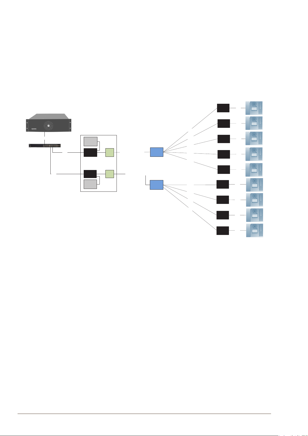
2.5 System Configuration with Central Powering of Remote Intercoms ...................................................... 8
2.6 System Configuration with Local Powering of Remote Intercoms........................................................... 9
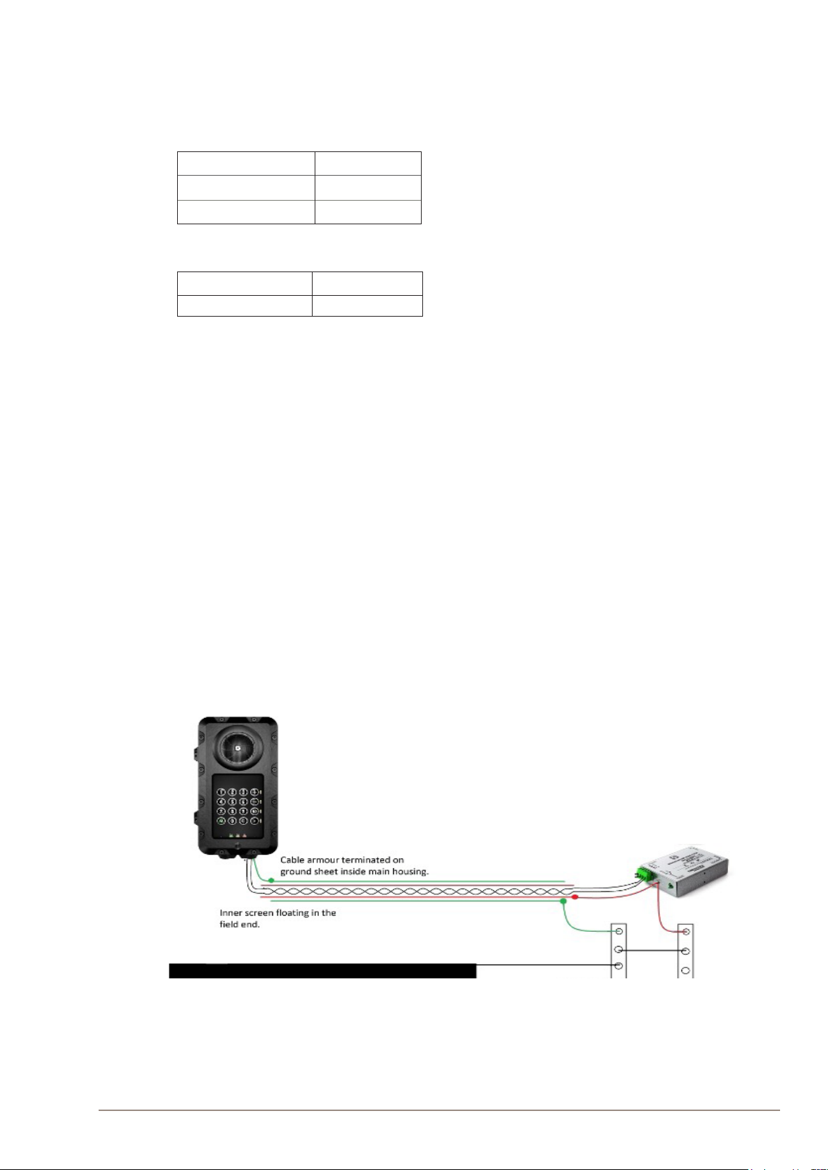
2.7 System Configuration with Industrial & Ex Devices.........................................................................................10
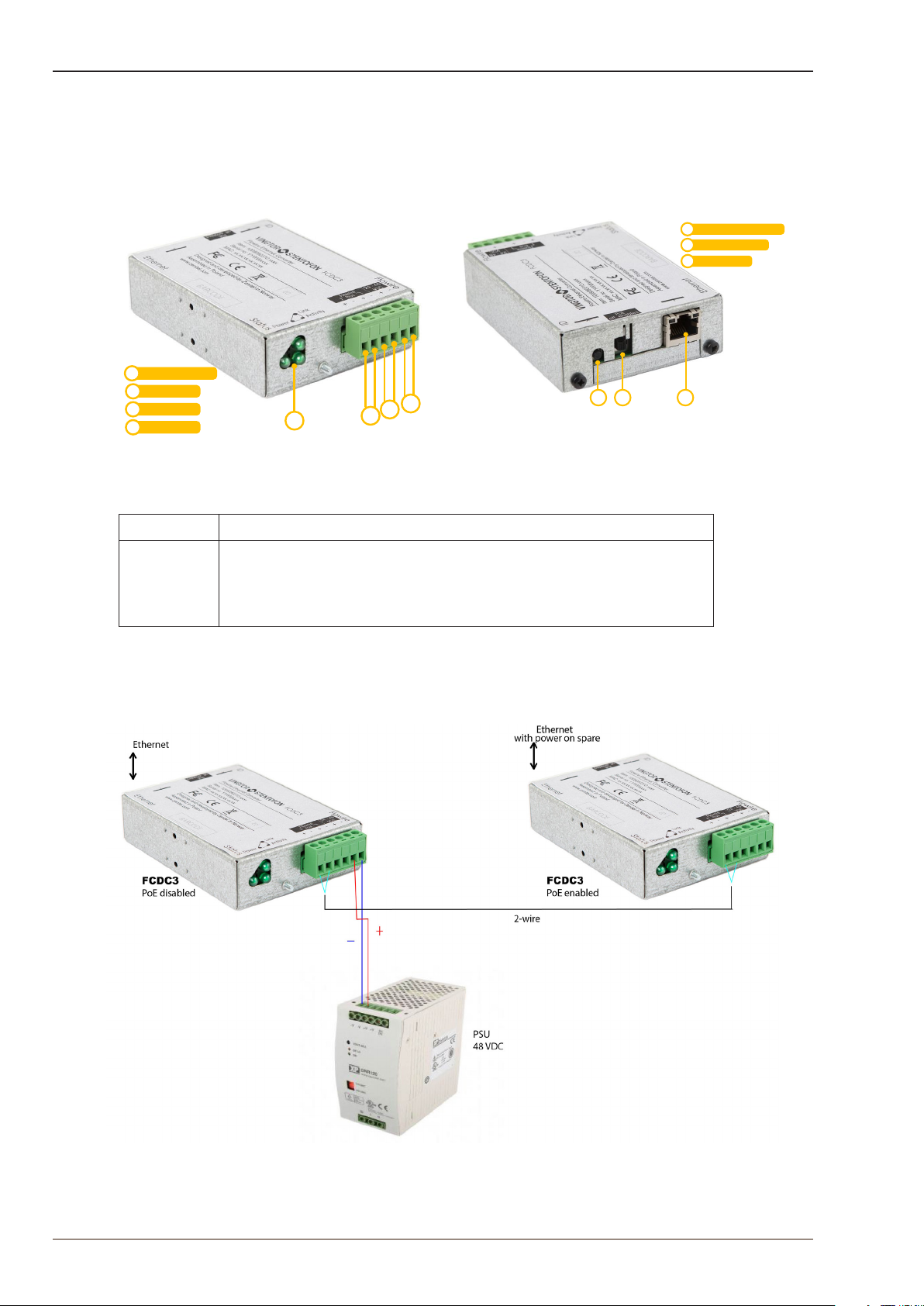
3 Connections & Indications...........................................................................................................................................................11
3.1 Flowire Connection..............................................................................................................................................................11
3.2 Ethernet Connection...........................................................................................................................................................11
3.3 Indicator LEDs.........................................................................................................................................................................11
3.4 Password Reset Button.....................................................................................................................................................11
4 Mounting & Recommendations ...............................................................................................................................................12
4.1 Mounting the Flowire Converter..................................................................................................................................12
4.2 Power Requirements......................................................................................................................................................... 13
5 Troubleshooting............................................................................................................................................................................... 14
5.1 Power for Stable Connection at Remote Site..................................................................................................... 14
5.2 Cables & Bandwidth........................................................................................................................................................... 14
5.3 System Log ............................................................................................................................................................................. 14
A: Power Consumption & Distances for Typical Cables..................................................................................................17
B: Advanced Configuration............................................................................................................................................................. 18
B.1 Setting a Static IP Address & Disabling DHCP.................................................................................................... 18
B.2 Network Management Key (NMK) Configuration............................................................................................ 19
B.3 CCo Settings.........................................................................................................................................................................20
C: Software Upgrade............................................................................................................................................................................21
C.1 Upgrade via Web Interface on Flowire Device.....................................................................................................21
D: Upgrade FCDC1/FCDC2, EAPFX, TFIX to Operate with FCDC3 ..................................................................... 22
Figures
Figure 1 FCDC3 Flowire Converter............................................................................................................................................................................................4
Figure 2 FCDC3 PoE Enabled and FCDC3 PoE Disabled.............................................................................................................................................4
Figure 3 Conventional star-wired infrastructure..................................................................................................................................................................6
Figure 4 Conventional star infrastructure with multi-pair cables and junction boxes ....................................................................................6
Figure 5 Flowire Upgraded configuration with central power distribution. ..........................................................................................................8
Figure 6 Conventional analog/digital system configuration..........................................................................................................................................9
Figure 7 Flowire Upgraded configuration with local power at remote locations...............................................................................................9
Figure 8 Cabling in Ex & Industrial Zones ...............................................................................................................................................................................10
Figure 9 FCDC3 Flowire Converter Dimensions...............................................................................................................................................................12
Figure 10 DIN Mounting Clips..........................................................................................................................................................................................................12

4A100K11958
FCDC3 Flowire Converter Configuration Manual
1 Product Description
1.1 General Description
The Flowire Converter enables Ethernet to run on the same two wires as power, providing simpler cabling
and opening up for longer cable hauls. The Flowire converter is also capable of powering the Ethernet
devices (Vingtor-Stentofon IP intercom stations) attached to it via spare pairs.
Power Input
PLC 1
PLC 22
3
4
234
1
Status Indicators1
2 3
Password Reset Button1
PoE On/ Off Switch2
1
Ethernet Port3
Figure 1 FCDC3 Flowire Converter
Model Description
FCDC3 24-48 VDC Flowire Converter with power-forwarding (PoE, type 2)
capabilities. Forwards 48V from the power supply to the spare pairs of the
Ethernet port (not true PoE) if PoE-switch is in the ON position. Does not
forward 48V to the spare pairs of the Ethernet port if PoE-switch is in the
OFF position
Figure 2 FCDC3 PoE Enabled and FCDC3 PoE Disabled

5
FCDC3 Flowire Converter Configuration Manual
A100K11958
LIt is recommended to use FCDC3 with PoE enabled only when you need to power the connected
device via the spare pairs of the Ethernet port. In all other situations, use the FCDC3 with PoE disabled.
1.2 Areas of Application
The main areas of application for the Flowire Converter are:
●Retrofitting older communication systems
●Providing Ethernet connectivity to remote locations in buildings
1.2.1 Retrofitting Older Intercom & Telephone Systems
●Analog and digital intercom systems
●Analog and digital telephone systems
The above solutions typically use a conventional star-wired telecom infrastructure with 0.5 mm2 (20 AWG)
single-pair twisted cables.
1.2.2 Remote IP Intercom Locations in New Buildings
In some new building projects, it is a challenge to provide Ethernet connectivity to remote locations (beyond
100 meters from the main equipment room) for critical communication.
By implementing Flowire Converters, it is possible to upgrade these systems with IP products without costly
and time consuming re-cabling of CAT or fiber cables.
1.2.3 Cable Length
Cable length should be 600 meters maximum.

6A100K11958
FCDC3 Flowire Converter Configuration Manual
2 Upgrading Conventional Star-Wired Infrastructure
2.1 The Conventional System
A conventional star-wired infrastructure supports analog and digital intercom and telephone systems. These
star-wired telecom infrastructures are typically used in both marine and onshore intercom applications.
Figure 3 Conventional star-wired infrastructure
In this solution, you will have a centralized equipment rack with the following equipment:
●Telecom / Intercom Exchange
●Power Supply Unit
●Main Distribution Frame
The Main Distribution Frame connects the exchange to subscriber lines connected in a star structure.
Figure 4 Conventional star infrastructure with multi-pair cables and junction boxes
In order to simplify maintenance and reduce cabling costs, it is common to use multi-pair cables and junction
boxes in order to branch out to dierent locations.
Conventional star-wired telecom infrastructures commonly use one twisted wire pair to each telecom
device. However, many systems, like AlphaCom, use two twisted pairs for each telecom device

7
FCDC3 Flowire Converter Configuration Manual
A100K11958
2.2 Power on Conventional Infrastructure
In an analog and digital telecom/intercom system, it is usually a requirement to power the telephones/
intercoms from the central equipment rack, thus supplying the power over the subscriber line.
Typical maximum subscriber line distances for intercom systems are:
Wire cross section Distance
0.6 mm2 (19 AWG) 2.0 km
0.5 mm2 (20 AWG) 1.4 km
Table 1 AlphaCom Subscriber Line Distance
Wire cross section Distance
0.5 mm2(20 AWG) 0.8 km
Table 2 AsaCom Subscriber Line Distance
2.3 Precaution & Limitations
●The cable shields must be interconnected in junction boxes and grounded in the central device only.
●Never use a cable run where the voltage drops below half of the PSU voltage.
●Do not connect more than 9 Flowire Converters on one Flowire star configuration.
●Powering of remote IP intercom stations through their Ethernet ports requires at least 40 VDC at the
remote site.
2.4 Grouding
2.4.1 Installlations in Non-Ex Areas
It is always good practice to ground the cabinet of equipment installed in racks. This ensures safety and good
EMC. The grounding connection of the Flowire Converter should be connected to the equipment rack’s
ground strip using a ground wire of at least 0.75 mm² (AWG 19).
2.4.2 Grounding of Ex-Stations
Figure 5 For Ex-stations, connect the screen according to this illustration.

8A100K11958
FCDC3 Flowire Converter Configuration Manual
2.5 Recommendations
●Use twisted-pair shielded cables
●Unless the cables are shielded, you should avoid running wires from dierent Flowire star
configurations in the same cable ducts.
●Avoid multi-pair cables with connections to other systems.
●If you are using a multi-pair cable, but not all its pairs, connect more pairs between two Flowire
Converters to reduce voltage drop and increase bandwidth.
2.6 System Configuration with Central Powering of Remote Intercoms
Figure 6 Flowire Upgraded configuration with central power distribution.
In the figure above, there are two Flowire star configurations, each with one central FCDC3 Flowire
Converter with PoE disabled and one central PSU (Power Supply Unit). FCDC3 with PoE enabled is used
to power the connected device via the spare pairs of its Ethernet port. There can be no cross connection
between these star configurations inside the main distribution frame.
The figure above shows how the Flowire upgraded system configuration will look like when all remote IP
products are powered by centrally located PSUs.
LOnly use FCDC3 with PoE disabled together with the central PSU in the main distribution frame.
LAll multi-pair cables for one Flowire star configuration has to be gathered in the central FCDC3. This can
be done directly in the FCDC3 if the plug has room for it, on connector rails or by some other means.
LYou should avoid cross connecting two Flowire star configurations.
LYou should avoid having wires from dierent Flowire star configurations share the same multipair cable
as this will lead to a very detrimental form of crosstalk.
LYou must never ground any of the devices at the remote sites as this may draw additional current from the
central PSU to the remote sites, thus reducing the power distribution performance.
2.7 System Configuration with Local Powering of Remote Intercoms
Jun cti on
bo x
Jun cti on
bo x
2-wire
2-wire
2-wire
2-wi re
2-wi re
2-wi re
Ga the r mu l ti pairs w he n
connecting to Flowire
FCDC3
FCDC3
M ain Dis tr ibu ti on Fra me
2-wire/multipair cable
CAT
CAT
PS U
PS U
CAT
FCDC3
FCDC3
FCDC3
FCDC3
CAT
CAT
CAT
CAT
FCDC3 CAT
2-wire
2-wi re
2-wire
FCDC3
FCDC3
FCDC3
FCDC3
CAT
CAT
CAT
CAT
Po E e na bl ed
Audio Server
PoE disabled
PoE disabled
Po E e na bl ed
Po E e na bl ed
Po E e na bl ed
Po E e na bl ed
Po E e na bl ed
Po E e na bl ed
Po E e na bl ed

9
FCDC3 Flowire Converter Configuration Manual
A100K11958
Figure 7 Conventional analog/digital system configuration
Figure 8 Flowire Upgraded configuration with local power at remote locations
Junction
bo x
Junction
bo x
FCDC3
FCDC3
FCDC3
FCDC3
FCDC3
FCDC3
2-wire
2-wire
2-wire
2-wire
2-wire long haul
2-wire long haul
CAT
CAT
CAT
CAT
CAT
CAT
PoE injector CAT
PoE
Switch
FCDC3
FCDC3
Main Distribution Fr ame
2-wire/multipair cable
CAT
CAT
PS U
PS U
CAT
Po w er
C on ne ctor
2-wire/multipair cable
Po w er
C on ne ctor
PLC
C on ne ctor
PLC
C on ne ctor
PoE disabled
PoE disabled
PLC
C on ne ctor
PLC
C on ne ctor
Po E e na bl ed
Audio Server
PoE disabled
PoE disabled
Po E e na bl ed
Po E e na bl ed
Po E e na bl ed
Cross connect
Flat cable
Flat cable
Multipair cable
2 wire
2 wire
2 wire
2 wire
2 wire
Junction
box
Junction
box
Multipair cable
2 wire
2 wire
2wire
2 wire
Main distribution frame

10 A100K11958
FCDC3 Flowire Converter Configuration Manual
Red cables indicate long hauls where local power will be necessary to maintain a stable connection to the
intercoms. FCDC3 with PoE enabled is used to connect to local power for intercoms at remote
locations. For single stations, a PoE injector will be ideal. For groups of intercom stations, it may be better to
use a PoE switch.
LDO NOT enable PoE on FCDC3 connected to local power for intercoms at remote locations.
LMaximum number of Flowire devices per star configuration is 9 (1 in main frame and 8 outside)
LONLY use twisted-pair cables.
2.8 System Configuration with Industrial & Ex Devices
The Ex device (TFIX station, EAPFX access panel) located in a hazardous zone is connected to the central
equipment rack located in the safe zone using an Ex certified 2-wire shielded cable. FCDC3 is used to extend
the Ethernet connection and support power distribution on the 2-wire cabling infrastructure.
Each industrial device (TFIE station, EAPII access panel) located in an outdoor area will require its own
FCDC3 Flowire Converter.
To support the Flowire interface, the central equipment rack must be equipped with an FCDC3 PoE-disabled
Flowire Converter.
Figure 9 Cabling in Industrial Zones
LDo NOT enable PoE on FCDC3 in the central equipment rack.

11
FCDC3 Flowire Converter Conguration Manual
A100K11958
3 Connections &
Indications
3.1 Flowire Connection
The Flowire Converter (FCDC3) must be connected to the
Flowire network star configuration using twisted cabling
with positive and negative DC voltage connected as shown
on the label. The power supply voltage used depends on
the type of devices in the star configuration.
48 VDC PSU : Recommended when using Flowire with
Zenitel IP intercoms and access panels.
24 VDC PSU : When using Flowire with Zenitel legacy Ex
intercoms and access panels.
The converter is equipped with one dedicated power input
connection and two connections to the other Flowire
converters (PLC 1 & PLC 2).
Please note that the two connections (PLC 1 and PLC 2) are
equivalent and that Power Input MUST NOT be connected
to other converters.
Power Input
PLC 1
PLC 22
3
4
234
1
Status Indicators1
For the first converter unit on the configuration, the power
input connection shall be used to connect the power
supply, while the other connections can be used to connect
to the actual star configuration. The power supply may be
connected to the power input connection at any point on
the star configuration, i.e. it can be connected to any of the
Flowire Converters on the star configuration, but only to
ONE converter per cluster.
3.2 Ethernet Connection
Ethernet is connected via the RJ45 port. This supports 1
Gbps Ethernet (in and out) and power out over spare pairs.
Use the switch next to the RJ45 port to enable/disable PoE
power to the spare pairs. The power on the spare pairs
is the same voltage as the one supplied to the converter.
Hence, at least 40 volts must be applied to the converter
in order to ensure stable operation when powering IP
intercom stations directly through their Ethernet ports. If
the station has a 24-volt input, the voltage can be reduced
to 24 volts by separating the spare pairs from the CAT cable
and connecting it to this input.
2 3
Password Reset Button1
PoE On/Off Switch2
1
Ethernet Port3
LDo NOT power the Flowire Converter through the RJ45 Eth-
ernet port. Trying to do so with a PoE injector will damage the
converter.
LThe RJ45 port on FCDC3 is NOT a PoE-compatible output
but DC voltage on spare pairs which is always present. It must
NOT be connected to any equipment that can be damaged by
this voltage when PoE is enabled.
3.3 Indicator LEDs
The Flowire Converter is equipped with three green LEDs.
These indicate the status of the power, the connection/link
to Flowire, and whether data is transmitted on Flowire or
not.
3.4 Password Reset Button
Pressing and holding this button for more than 15
seconds will reset the NMK password to the default:
HomePlugAV0123
LED1 - Power: This LED is lit when
the converter is receiving enough
power for powering up.
LED2 - Link: This LED is lit when
the converter recognizes one or
more converters on the Flowire star
configuration.
LED3 - Activity: This LED flashes
when data is transmitted to or from
the converter.
In addition to resetting the
NMK password to its default,
the procedure will also set the
following factory defaults:
●DHCP will be turned on
●IGMP snooping will be
disabled.

12 A100K11958
FCDC3 Flowire Converter Configuration Manual
4 Mounting & Recommendations
4.1 Mounting the Flowire Converter
The Flowire Converter should be mounted on-wall by using 2 x 4 mm screws or on NS35 DIN rail by using the
mounting clips provided in a normal and ventilated indoor environment with a maximum temperature of 70°C.
Make sure that there is sucient space for cables and maintenance. When using more than one Flowire
Converter, try to mount them minimum 2cm apart from each other.
Figure 10 FCDC3 Flowire Converter Dimensions
1 2 3 4
Alternate DIN Clip Hole s3
DIN Mounting Clip1
Mounting Holes2
DIN Mounting Clip4
Figure 11 DIN Mounting Clips
To mount the Flowire Converter:
●Press the Flowire Converter against the DIN rail of the rack until the mounting clips snap into place.
Power
Link
Activity 24 - 48
VDC
+ - + -
Flowire
Reset
Status
Ethernet
Flowire Ethernet Converter
Item: 1008080310.xxxx
Serial no: YYWWxxxx
MAC: xx:xx:xx:xx:xx:xx
Designed and developed by Zenitel Norway
Assembled in Poland
www.zenitel.com
FCDC3
PoE
Off On
flowire
Bus
+ -
9
74
26
4
62
37,5
26
Reset
Ethernet contact
Brackets for NS35 rail mount
Part of the package (2pcs)
Ø8
102
Cable entry
PoE Switch On/Off

13
FCDC3 Flowire Converter Configuration Manual
A100K11958
4.2 Power Requirements
A Flowire Converter needs at least 18V to operate, nominal voltage is 24V to 48V, and maximum voltage is
56V. The voltage at the remote Flowire Converter should never drop below half of the PSU’s output voltage.
To power a Vingtor-Stentofon IP Intercom Station through its Ethernet port, we recommend at least 40V at
the remote site.
For land-based installations, use XP PSU for FCDC3:
-XP 120 XP Power Supply Unit, 48V DC, 120W
Item no. 2990101120
-XP 240 XP Power Supply Unit, 48V DC, 240W
Item no. 2990101240
For maritime installations use Wago PSU for FCDC3:
-Wago 787-1623 Power supply 100-240VAC/48VDC 2A
Item no. 2990000065
-Wago 787-1633 Power supply 100-240VAC/48VDC 5A
Item no. 2990000066
If one or several Flowire clusters is powered from a PSU that can deliver more than 3A each Flowire in the
system rack should have a 3A fuse on the power input. This power cable has no minimum length and does
not need to be twisted or shielded.
Figure 11 Using Power Supplies > 3A

14 A100K11958
FCDC3 Flowire Converter Configuration Manual
5 Troubleshooting
5.1 Power for Stable Connection at Remote Site
The minimum voltage at the remote end for PoE is 40VDC. The minimum voltage for the TFIX Ex intercoms
and EAPFX Ex access panels is 18VDC. For TFIX stations and EAPFX panels with external speaker the
minimum voltage is 30VDC.
The PoE voltage can be read on the device’s web interface:
●Select Device Info > PoE
Voltage and Current values shown are out of the FCDC3.
If you are not getting sucient voltage for a stable connection at the remote site, you can:
●Adjust the output voltage on the PSU
●Use local power supply for the connected equipment
●Route the spare pairs in the Ethernet cable to the intercom station’s 24V input (available on most
Vingtor-Stentofon IP intercom stations and kits except for desktop master stations)
5.2 Cables & Bandwidth
●To get the best bandwidth you should use twisted-pair shielded cables.
●When using multi-pair cables, there should ideally not be any trac on the pairs not being used for the
Flowire Converter. A point-to-point connection between two Flowire Converters, however, will get
better bandwidth when more wires are connected between them.
●Avoid unnecessary splicing. A continuous cable will carry the signal further.
●Regarding EMI, twisted/shielded cabling is highly recommended. When using unshielded parallel
cables, try to avoid running them close to devices emitting strong fields in the 2 to 86 MHz bandwidth.
●Regarding cross-talk, there will always be some cross-talk when running unshielded cables close to
each other or when using several pairs in a multi-pair cable for dierent devices. However, the most
detrimental cross-talk can occur between dierent Flowire star configurations.
5.3 System Log
To enable system logging:
●Select Management > System Log
●Click Configure System Log

15
FCDC3 Flowire Converter Configuration Manual
A100K11958
Select the log levels to log and to display. The Mode dropdown box selects where the log is recorded.
If Local is selected the log will be saved in the local memory.
If Remote is selected the log will be sent to the syslog server that is set up in Server IP Address.
If Both is selected the syslog will be stored locally and sent to the syslog server.
Local syslog:

16 A100K11958
FCDC3 Flowire Converter Configuration Manual
Log shown in a syslog server:
Since there is no real time clock in the FCDC3, the timestamp in the device is related to the start-up time of
the FCDC3.

17
FCDC3 Flowire Converter Configuration Manual
A100K11958
A: Advanced Configuration
IP addresses on a Flowire device can be set either by setting a static IP address or having one assigned from
a temporary DHCP server. The Flowire device has, by default, DHCP enabled on one of their networking
interfaces.
A.1 Setting a Static IP Address & Disabling DHCP
By default, all Flowire devices have 169.254.1.10 as a static IP address.
In order to set a new static IP address:
1. Isolate the Flowire device by disconnecting the line to other devices (if you have more than one
Flowire device with default IP configuration).
2. Access the web interface of the Flowire device via the default address 169.254.1.10.
3. Select Advanced Setup > LAN
4. Select Disable DHCP Client
5. Enter the new IP address, Subnet Mask and Default Gateway
6. Click the Apply/Save button
The device will now use its new IP address.

18 A100K11958
FCDC3 Flowire Converter Configuration Manual
A.2 Network Management Key (NMK) Configuration
To set a new NMK password:
1. Log into the Flowire device by entering its IP address in a web browser.
2. Select Advanced Setup > HomePlug > Network password
3. Enter a new password in the Network password field
4. Click Apply/Save
The NMK Password may be up to 32 characters long, and is case sensitive.
It is good practice to label the Flowire device with the new NMK.
Default NMK: HomePlugAV0123

19
FCDC3 Flowire Converter Configuration Manual
A100K11958
A.3 CCo Settings
●Select Advanced Setup > HomePlug
In the Flowire web interface, each Flowire unit has a setting for CCo (Central Coordinator). In every Flowire
network, there is always one CCo, but this is, by default, automatically selected. If the CCo should fail, another
Flowire unit on the network is automatically selected to be CCo. In a star configuration, in order to optimize
availability, it is recommended to always configure the FCDC3 in the rack to be CCo. Due to its location, it
is least likely to suer damage. If this Flowire unit fails, the star configuration will not function in any case,
whether or not it is the CCo, as all other Flowire units are routed through it. In order for the FCDC3 in the rack
to be configured as a CCo, it is necessary to set the device-side Flowire units to not CCo.
●For one-to-one connections, this setting can be left as Auto/Blank.
LNote: After changing CCo settings, the Flowire unit needs to be rebooted.
For more information, see the wiki page Flowire CCo on this subject.
A.4 Multicast and IGMP
FCDC3 has support for IGMP snooping. By default, IGMP snooping is disabled. It is possible to enable and
disable IGMP snooping from the FCDC web (Advanced Setup/IGMP). (Versions prior to vsf-fcdc3-1.0.3.1 has
IGMP snooping enabled, and no web config support for IGMP snooping).
FCDC3 does not have built in IGMP querier.
When IGMP snooping is disabled, FCDC3 will send a multicast packet to all other devices in the cluster. The
packet is sent separately to each of the other devices on a fast unicast channel. (As opposed to sending it
once on a slow broadcast channel)
When IGMP snooping is enabled, FCDC3 will only send a multicast packet to the devices that has expressed
interest in the multicast address via IGMP.
FCDC3 IGMP snooping has some limitations, that is why it is disabled by default.
It does not work properly with IGMPv2 for groupcalls. There is a delay of multiple seconds before all stations
join the groupcall.
FCDC3 can only track 16 dierent multicast streams ( usually not a problem)
Each multicast group can only have 8 members.
If the network use IGMPv3, and there are less than 9 FCDC in the cluster, it is safe to enable IGMP snooping.
On point-to-point links IGMP snooping do not add any value.

20 A100K11958
FCDC3 Flowire Converter Configuration Manual
A.5 Multicluster Separation
A.5.1 Multicluster Groups and Separation
Crosstalk is a phenomenon by which a signal transmitted on one circuit creates an undesired eect in
another circuit and it is caused by capacitive, inductive, or conductive coupling from one circuit or to another.
When several Flowire clusters are installed physically close to each other there may be crosstalk between
the clusters. Furthermore, when using common power supply to several Flowire clusters they will also be in
the same multicluster group due to interference through the power cable.
To prevent crosstalk from one Flowire interfering with the communication in another cluster a unique
Network password should be defined for each cluster. All Flowires within the same cluster should have the
same Network Password.
LNOTE! There are 16 cluster ID’s available allowing maximum 16 Flowire clusters in one multicluster
group. Having more than 50 Flowire units in one multicluster group should also be avoided.
LTo avoid exceeding the limit of clusters or devices in a multicluster group sucient physical separation
should be implemented between the Flowires installed on the systems side.
Figure 11 Multicluster Groups
Other manuals for Vingtor Stentofon FCDC3
1
This manual suits for next models
1
Table of contents
Other Zenitel Network Hardware manuals
Popular Network Hardware manuals by other brands

2N Telekomunikace
2N Telekomunikace ATEUS STARGATE user manual

FieldServer
FieldServer Metasys N2 FS-8700-19 Driver manual

Verbatim
Verbatim MediaShare user manual

HIK VISION
HIK VISION HiWatch Series quick start guide

ARM
ARM AMBA NIC-301 Technical reference manual

HP
HP Mv2120 - Media Vault Network Drive user guide