Zenith STOL CH750 User manual

STOL
CH750 Zenith Aircraft Company
www.zenithair.com
Rear Fuselage Top Skin & Rear Fuselage
Assembly
Section 75-FA-2Page 1 of 9
Revision 2.0 (8/13/2010)
© 2010 Zenith Aircraft Co.
Section 75-FA-2
Top Fuselage Skin
& Rear Fuselage Assembly
This manual has been prepared for assembly of the rear fuselage supplied with match drilled parts. This
photo assembly manual is intended as a supplement to the drawings. If there is any discrepancy between
this manual and the drawings, the drawings supersede this manual. For more information on building
standards and allowable tolerances see “Construction Standards for Zenair Light Aircraft” available from
Zenith Aircraft Co.

STOL
CH750 Zenith Aircraft Company
www.zenithair.com
Rear Fuselage Top Skin & Rear Fuselage
Assembly
Section 75-FA-2Page 2 of 9
Revision 2.0 (8/13/2010)
© 2010 Zenith Aircraft Co.
Install the lateral L angles and diagonal L angles to the Top Skin as previously done
on the other Rear Fuselage Skins. The lateral L angles overlap the Longeron rivet
lines. The diagonal L angles do not overlap any other parts.
Reference: See drawing 75-FA-2 for L angle locations and orientation.
P/N: 75F2-1
Top Skin
Cleco the Rear Side Skin to the Rear H.T. Frame. Check the bottom of the Rear Side Skin to be sure it is
positioned correctly on the Longeron. The Skin edge should be against the lip on the Longeron at the start of
the radius. With a #30 drill bit, back drill through the Rear Side Skin into the Longeron and Cleco. With a #20
drill bit, expand the holes through the Rear Side Skin into the Rear H.T. Frame and Cleco.

STOL
CH750 Zenith Aircraft Company
www.zenithair.com
Rear Fuselage Top Skin & Rear Fuselage
Assembly
Section 75-FA-2Page 3 of 9
Revision 2.0 (8/13/2010)
© 2010 Zenith Aircraft Co.
Cleco the Side Skin to the Forward H.T. Frame and to the Rear Side Skin. A 2”x4” has been screwed to the
work bench with another board screwed to it to clamp the Side Skin to. This will support the front end of the
Side Skin. Check the bottom of the Side Skin is positioned correctly on the Longeron, the Side Skin should
set against the lip on the Longeron. With a #30 drill bit, back drill through the Side Skin into the Longeron
and Cleco. With a #20 drill bit, expand the holes through the Side Skin into the Forward H.T. Frame.
Cut an L angle to fit between the H.T. Frames on a diagonal. Draw a center line on one flange and position it
over the holes on the Side Skins. With a #40 drill bit, back drill through the Side Skins into the L angle and
Cleco the L angle to the Side Skins. With a #20 drill bit, expand the holes and Cleco.

STOL
CH750 Zenith Aircraft Company
www.zenithair.com
Rear Fuselage Top Skin & Rear Fuselage
Assembly
Section 75-FA-2Page 4 of 9
Revision 2.0 (8/13/2010)
© 2010 Zenith Aircraft Co.
Install the opposite Side Skins using the same procedures used to install the first side.
Cleco the Longerons on to the top of the Side Skins.

STOL
CH750 Zenith Aircraft Company
www.zenithair.com
Rear Fuselage Top Skin & Rear Fuselage
Assembly
Section 75-FA-2Page 5 of 9
Revision 2.0 (8/13/2010)
© 2010 Zenith Aircraft Co.
Cut two L angles to fit between the Side Skins at the top of the H.T. Frames. Clamp the L angles to the
Longerons and the H.T. Frames. With a #40 drill bit, back drill through the H.T. Frames into the L angle and
Cleco. With a #20 drill bit, expand the holes in the H.T. Frame and L angles and Cleco.
Cleco the Uprights and Side Channels to the Side Skins.
Note: The photo above has the Top Skin installed; this is done in a following step.
P/N: 75F3-4
Upright
P/N: 75F4-1
Side Channel

STOL
CH750 Zenith Aircraft Company
www.zenithair.com
Rear Fuselage Top Skin & Rear Fuselage
Assembly
Section 75-FA-2Page 6 of 9
Revision 2.0 (8/13/2010)
© 2010 Zenith Aircraft Co.
P/N: 75F3-9
Rear Top Channel
Angle
P/N: 75F3-7
Rear Top Channel
P/N: 75F3-6
Top Channel
Cleco the Rear Top Channel Angle to the Rear Top Channel. With a #30 drill bit, expand the holes on the aft
flange and Cleco. In the photo above, the aft flange is the flange with the two Clecos installed. Then with a
#20 drill bit, expand the holes. Leave the holes in the top #40 until they are installed on the Fuselage.
Cleco the Top Channel to the Rear Top Channel. The Rear Top Channel fits inside the Top Channel. Use a
#30 drill bit to expand the holes, then a #20 drill bit to expand the holes and Cleco.

STOL
CH750 Zenith Aircraft Company
www.zenithair.com
Rear Fuselage Top Skin & Rear Fuselage
Assembly
Section 75-FA-2Page 7 of 9
Revision 2.0 (8/13/2010)
© 2010 Zenith Aircraft Co.
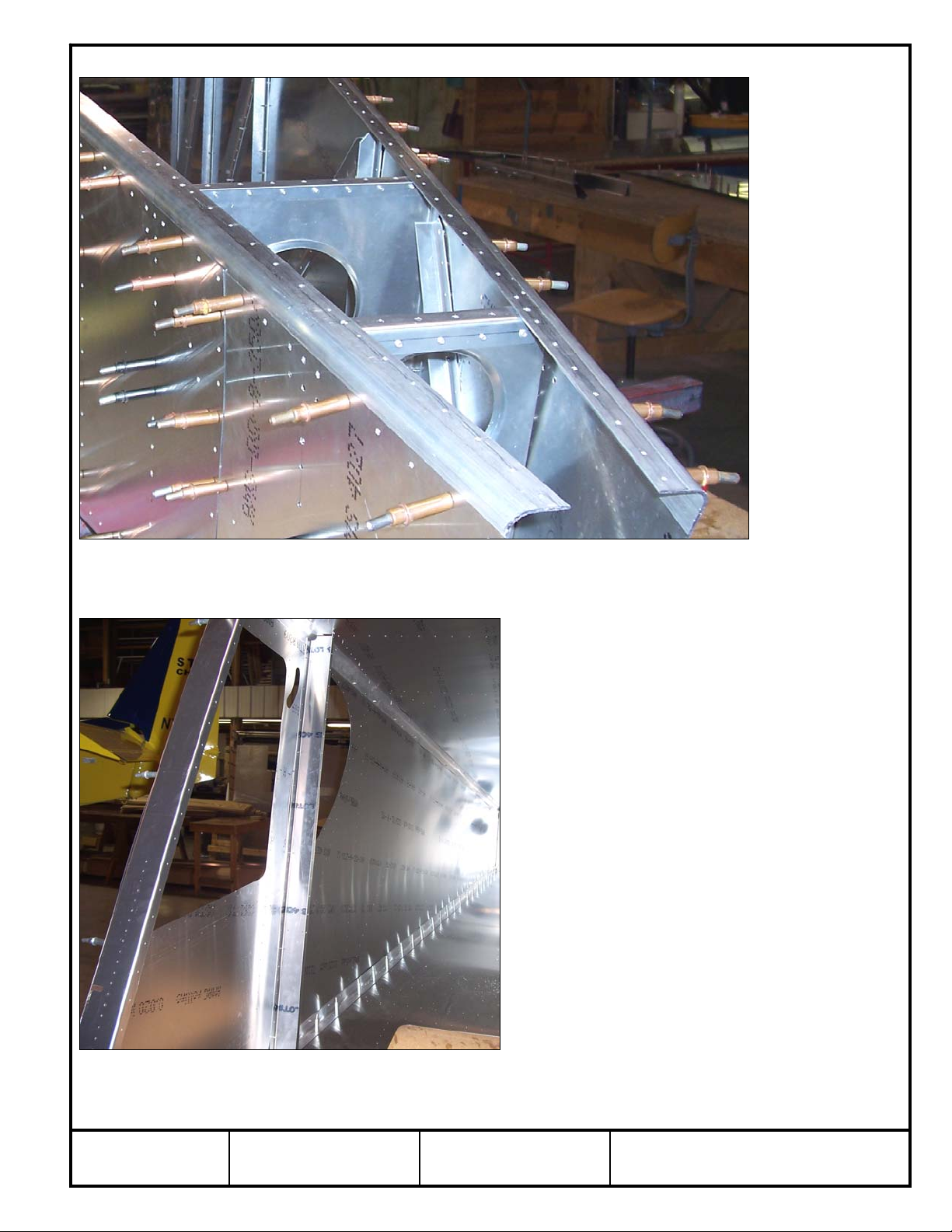
With a hacksaw, trim the excess Longeron off flush with the edge of the Side Skin.
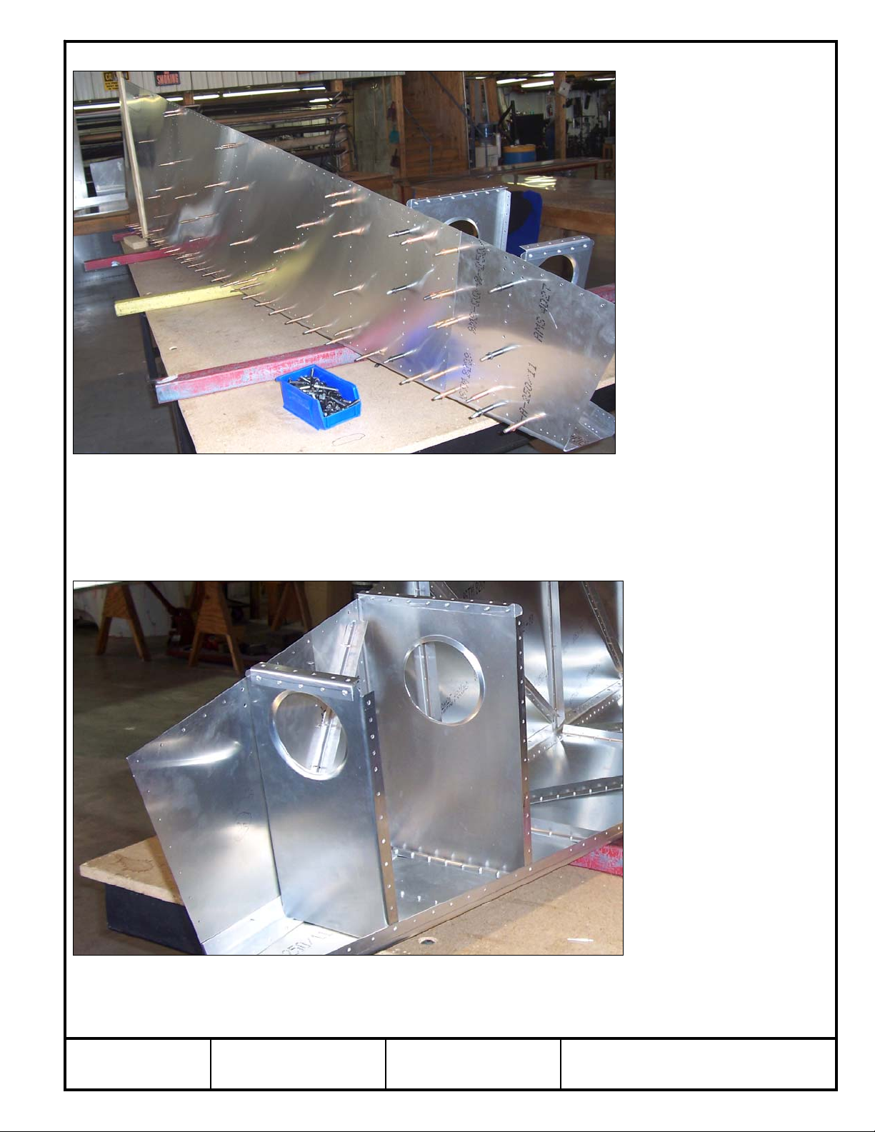
Cleco the Rear Wing Attachment to the Side Channel and the Top Channel to the
Rear Wing Attachment. This will support the Side Skins and help square the Rear
Fuselage. Use a #30 drill bit, then #20 drill bit, and finally a #12 drill bit to expand the
holes in the Rear Wing Attachment and Cleco.
Note: The above photo has the Top Skin and Top Doubler installed, this is done in
the following steps.
P/N: 75F4-4
Rear Wing
Attachment
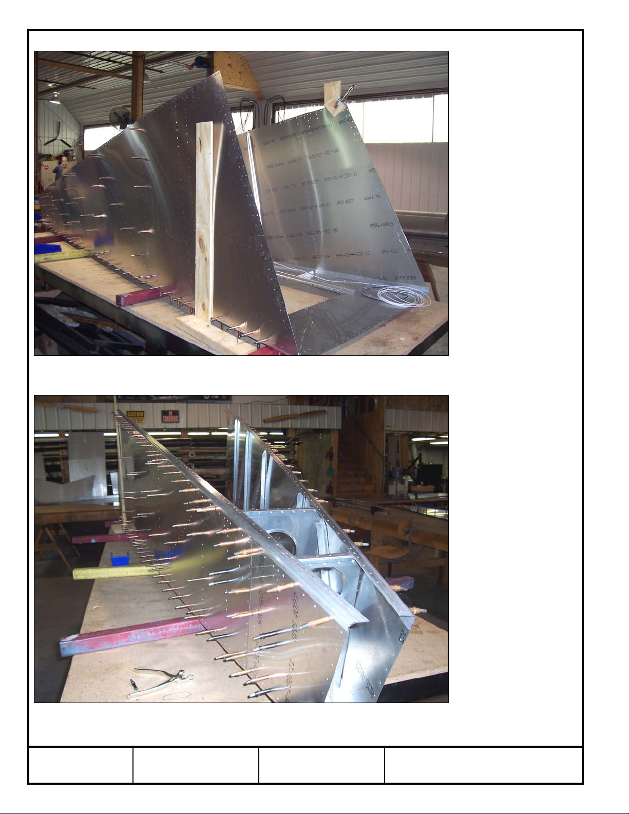
Position the Top Skin on the Rear Fuselage. Cleco the Top Skin to the Top Channel. With a #40 drill bit,
back drill through the Top Skin into the Longerons. Start at the front and work aft and Cleco every third hole.
With a #30 drill bit, expand the holes through the Longeron. Wait to drill the holes common with the Top
Doubler.
Check: Make sure the Top Skin is against the lip on the Longeron and not on top of the radius of the
Longeron.

STOL
CH750 Zenith Aircraft Company
www.zenithair.com
Rear Fuselage Top Skin & Rear Fuselage
Assembly
Section 75-FA-2Page 8 of 9
Revision 2.0 (8/13/2010)
© 2010 Zenith Aircraft Co.
Cleco the Top Doubler to the Top Skin. With a #20 drill bit, back drill through the Top
Doubler into the Top Skin and Longeron. With a #12 drill bit, expand the holes
through the Top Doubler into the Top Channel and Top Rear Channel. With a #20
drill bit, expand the remaining holes in the Top Channel and Rear Top Channel
through the Top Skin.
P/N: 75F4-3
Top Doubler
P/N: 75F3-1
Middle Rudder Hinge
Plate
P/N: 75F3-3
Rudder Hinge Shim
P/N: 75F3-2
Lower Rudder Hinge
Plate

STOL
CH750 Zenith Aircraft Company
www.zenithair.com
Rear Fuselage Top Skin & Rear Fuselage
Assembly
Section 75-FA-2Page 9 of 9
Revision 2.0 (8/13/2010)
© 2010 Zenith Aircraft Co.
With a hacksaw, trim the Longerons flush with the aft edge of the Bottom Skin and the Side Skins. Cleco the
Middle Rudder Hinge Plate, Rudder Hinge Shim, and Lower Rudder Hinge Plate to the Bottom Skin. The
Rudder Hinge Shim is positioned between the Longerons and flush with the aft edge of the Bottom Skin. Use
a #30 drill bit to expand the holes, then expand the holes with a #20 drill bit and Cleco. Expand the center
hole to 5/16” for the Tie Down Ring.
Cleco the Upper Rudder Hinge Plate to the Top Skin (not shown) and Longerons.
Expand the holes to 3/16”.
P/N: 75F2-7
Upper Rudder Hinge
Plate
Other manuals for STOL CH750
1
This manual suits for next models
1
Other Zenith Aircraft manuals