Zennio ZVI-TMDP4 User manual

KNX Capacitive Touch Switch
(4/6/8 Main Buttons + 5 Additional Buttons)
ZVI-TMDP4
ZVI-TMDP6
USER MANUAL
ZVI-TMDP8
Application Program Version: [1.2]
User Manual Version: [1.2]_a
www.zennio.com

Touch-MyDesign Plus
http://www.zennio.com Technical Support: http://zennioenglish.zendesk.com/
2
CONTENTS
Contents ........................................................................................................................................ 2
Document Updates ....................................................................................................................... 4
1 Introduction ............................................................................................................................. 5
1.1 Touch-MyDesign Plus ....................................................................................................... 5
1.2 Installation........................................................................................................................ 6
2 Configuration ........................................................................................................................... 8
2.1 General Configuration ...................................................................................................... 8
2.2 Touch Buttons ................................................................................................................ 12
2.2.1 Main Buttons .......................................................................................................... 13
2.2.1.1 Disabled........................................................................................................... 14
2.2.1.2 Pair .................................................................................................................. 14
2.2.1.3 Individual......................................................................................................... 20
2.2.2 Additional Buttons.................................................................................................. 33
2.2.2.1 Temperature Setpoint..................................................................................... 34
2.2.2.2 1-Byte Control (Unsigned Integer).................................................................. 35
2.2.2.3 1-Byte Control (Scaling) .................................................................................. 36
2.2.2.4 Individual Buttons ........................................................................................... 36
2.3 LED illumination.............................................................................................................. 38
2.3.1 Illumination Modes................................................................................................. 38
2.3.2 Brightness Levels .................................................................................................... 41
2.4 Welcome Back Object .................................................................................................... 44
2.5 Locking the Touch Panel................................................................................................. 46
2.6 Sounds ............................................................................................................................ 47

Touch-MyDesign Plus
http://www.zennio.com Technical Support: http://zennioenglish.zendesk.com/
3
2.7 Inputs.............................................................................................................................. 50
2.8 Thermostat ..................................................................................................................... 51
2.9 Internal Temperature Sensor ......................................................................................... 52
ANNEX I: Communication Objects .............................................................................................. 53

Touch-MyDesign Plus
http://www.zennio.com Technical Support: http://zennioenglish.zendesk.com/
4
DOCUMENT UPDATES
Version Changes Page(s)
[1.2]_a
Changes in the application program:
•Individual buttons:
oNew functionality (non-
alternating control) in the
dimmer and shutter controls.
oDepen
dence of the dimming and shutter motion
directions to the corresponding status objects.
-
Minor text changes. -
Extension of the functionality of the 1-
button dimming
control. 25, 33
Extension of the functionality of the 1-button shutter control. 26, 34
Update of the communication object table. 57-66
[1.1]_a Changes in the application program:
•Internal optimisation of the ETS project. -

Touch-MyDesign Plus
http://www.zennio.com Technical Support: http://zennioenglish.zendesk.com/
5
1INTRODUCTION
1.1 TOUCH-MYDESIGN PLUS
Touch-MyDesign Plus is an updated version of the original Touch-MyDesign, the KNX
multifunction capacitive touch switch from Zennio. Like the classic model, Touch-
MyDesign Plus provides a fully customisable solution for the room control, including
hotel rooms, offices or any other environment where the user needs to control climate
systems, lighting, blinds, scenes, etc.
The versatility of the above functions is enhanced by the built-in analogue/digital
inputs, temperature sensor and thermostat function, and by an elegant and fully
customisable design of the front glass – customers can choose their button icons, texts
and colours and even personalise the background with their pictures, logos, etc.
The inexistence of a screen, menus or complex user interaction beyond simply
touching the buttons confers the device a notable ease of use.
Figure 1 Touch-MyDesign Plus (6-Button Model)
The most outstanding features of Touch-MyDesign Plus are shown next.
Fully customisable design of the front glass.
4 / 6 / 8 main touch buttons (depending on the model), which can operate as
individual or pair controls.

Touch-MyDesign Plus
http://www.zennio.com Technical Support: http://zennioenglish.zendesk.com/
6
5 additional touch buttons, which can operate as individual or joint controls.
Horizontal or vertical orientation.
Light indicator (LED) for every button, the state of which (on or off) can
depend on different factors according to the user’s needs.
Buzzer for an audible acknowledgement of user actions (with the possibility of
disabling it either by parameter or by object).
Possibility of locking / unlocking the touch panel through binary orders or
scenes, and of setting a timed/automatic locking of the device.
Welcome Back object (binary or scene), which will be sent to the bus on the
first touch of the button panel after a certain (parameterisable) standby period.
Two analogue/digital inputs (for motion sensors, temperature probes,
additional switches, etc.).
Thermostat function.
Built-in temperature sensor.
1.2 INSTALLATION
Figure 2 Touch-MyDesign Plus. Installation Process.
To install the device, it is first necessary to mount the metallic plate into a square/round
standard appliance box through the suitable screws. Next, Touch-MyDesign Plus is
connected to the KNX bus through the corresponding terminal on the rear side of the
1
2
3
4

Touch-MyDesign Plus
http://www.zennio.com Technical Support: http://zennioenglish.zendesk.com/
7
device, and then the input terminal is as well connected to the rear of the device.
Once the input terminal and the KNX terminal are connected, the device can be easily
mounted on the metallic plate by the action of the built-in magnets. After that, it is
necessary to slide it downwards to fix it through the security anchorage system.
Finally, it is advisable to check that the device is properly installed, and that only the
profile of the device becomes visible from above, from below and from both sides (the
metallic plate should be completely hidden).
This device does not need any external supply, as it is powered through the KNX bus.
Figure 3 Element diagram.
The programming button (4) may be pressed with the help of a thin screw to set Touch-
MyDesign Plus into the Programming Mode. After a short press, the programming
LED (5) will light in red. Note that if this button is held while plugging the device into the
KNX bus, the device will enter the Safe Mode. The LED will then blink in red.
Note:whenever the device recovers the bus power, an immediate self-calibration
process of the touch panel takes place. Please ensure to avoid making pressure over
the front glass while powering the device. If undesired effects arise during normal use,
please disconnect the device from the bus and connect it again, making sure that the
front glass is not touched during this process.
For detailed information about the technical features of Touch-MyDesign Plus and for
safety instructions for the installation process, please refer to the Datasheet bundled
with the original packaging of the device and also available at www.zennio.com.
1. Temperature Sensor.
2. KNX Connector.
3. Analogue/Digital Inputs.
4. Prog. Button.
5. Prog. LED.
6. Magnet.
7. Lower LEDs.
8. Upper LEDs.
9. Upper Touch Area.
7
8
9
5
1
6
3
2
4

Touch-MyDesign Plus
http://www.zennio.com Technical Support: http://zennioenglish.zendesk.com/
8
2CONFIGURATION
2.1 GENERAL CONFIGURATION
To make the device perform the desired functions, several options need to be
parameterised, either related to its general behaviour (horizontal/vertical orientation,
lock procedure of the touch panel, sounds, welcome back object, LED brightness
levels…) or specific for each button (function to be performed, behaviour of the
corresponding LED, etc.).
On the other hand, Touch-MyDesign Plus features two opto-coupled inputs, each of
which may be independently configured as a switch/sensor, a push-button, a motion
detector, or a temperature probe, so that external accessories can be connected to
the device. In the particular case of an external temperature probe (such as model
ZN1AC-NTC68 from Zennio), it will be possible to use it with independence of the built-
in temperature sensor of the device, which implements its own communication objects
and can be enabled and disabled in parameters.
ETS PARAMETERISATION
Figure 4 General Configuration.

Touch-MyDesign Plus
http://www.zennio.com Technical Support: http://zennioenglish.zendesk.com/
9
After importing the corresponding database in ETS and adding the device into the
topology of the project, the configuration process begins by right-clicking into the
device and selecting Edit parameters.
This will bring the window shown in Figure 4, which contains the following parameters:
Main Buttons: read-only parameter to make it evident that the Main Buttons
configuration tab (containing all the parameters involved in the configuration of
the main buttons of the device) is always enabled in the tab tree on the left. See
section 0 for details.
Additional Buttons: read-only parameter to make it evident that the Additional
Buttons configuration tab (containing all the parameters related to the
configuration of the additional buttons of the device) is always enabled in the
tab tree on the left. See section 0 for details.
Inputs: enables or disables the Inputs tab in the tree on the left, depending on
whether the device will or will not be connected any external accessories. See
section 2.7 for details.
Thermostat: enables or disables the Thermostat tab in the tree on the left,
depending on whether this function is needed or not. See section 0 for details.
Touch-MyDesign Plus Orientation: defines the orientation (“Horizontal” /
“Vertical”) of the device, with the aim of implementing a logical behaviour in the
two-button controls.
Figure 5 Device Orientation
Note: the particular behaviour of the two-button controls (which one does what)
is defined through Button Pair Action, as explained below.

Touch-MyDesign Plus
http://www.zennio.com Technical Support: http://zennioenglish.zendesk.com/
10
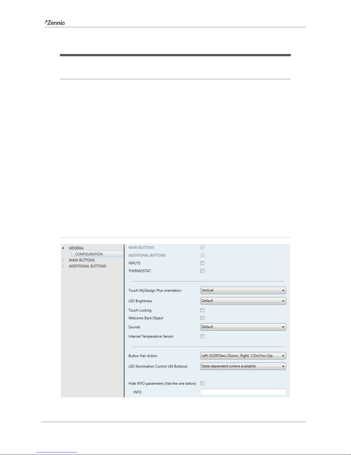
LED Brightness: sets whether the LEDs should make use of the pre-defined
brightness levels (“Default”) or of a user-defined configuration (“Custom”).
In “Default”, the LEDs will remain off while in the “off” state, and at the
maximum light level while in the “on” state.
In “Custom”, a specific tab will be included in the tab tree on the left so the
integrator can set the desired light levels for the “off” and “on” states and
whether to use the Night Mode or not.
See section 0 for details.
Touch Locking: enables or disables the Touch Locking tab in the menu on the
left, depending on whether this function is needed or not. See section 2.5 for
details.
Welcome Back Object: enables or disables the Welcome Back Object tab in
the tree on the left, depending on whether this function is needed or not. See
section 2.4 for details.
Sounds: sets whether the sound functions (button beeps, alarm and doorbell)
should work according to the pre-defined configuration (“Default”) or to a user-
defined configuration (“Custom”). See section 2.6 for details.
Internal Temperature Sensor: enables or disables the Internal Temperature
Sensor tab in the tree on the left, depending on whether this function is required
or not. See section 2.9 for details.
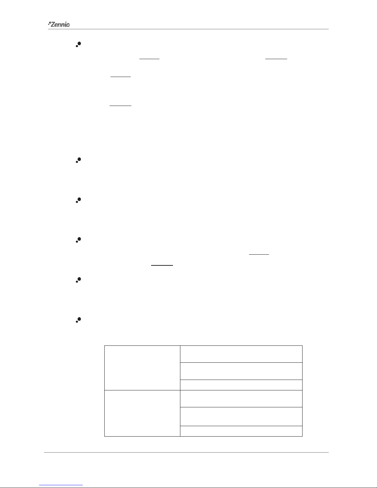
Button Pair Action: lets selecting how the two-button controls should behave
depending on the device orientation (see above):
Vertically-oriented
device
Left: 0 / Off / Decrease / Down.
Right: 1 / On / Increase / Up
Left: 1 / On / Increase / Up
Right: 0 / Off / Decrease / Down.
Every Button Pair is Configured Separately
Horizontally-oriented
device
Down: 0 / Off / Decrease / Down
Up: 1 / On / Increase / Up
Down: 1 / On / Increase / Up
Up: 0 / Off / Decrease / Down
Every Button Pair is Configured Separately

Touch-MyDesign Plus
http://www.zennio.com Technical Support: http://zennioenglish.zendesk.com/
11
In case of selecting “Every Button Pair is Configured Separately”, there will be a
specific parameter in every two-button control for specifically selecting the
desired behaviour (see section 2.2.1.2).
LED Illumination Control (All Buttons): sets how the LED indicators of all the
touch buttons should behave. The available options are (see section 2.3.1 for
details):
Regular,
State-Dependent (where available),
Dedicated Object,
Every button (pair) is configured separately.
In case of selecting “Every Button (Pair) is Configured Separately”, there will
be a specific parameter in every control for specifically selecting the desired
behaviour of the LED (or LEDs).
Hide Info Parameters: displays or hides the INFO textboxes on the top of the
parameter screen of each function. These textboxes have no functionality –
they are offered for the convenience of the integrator, as they allow assigning a
description to each control, which may be useful in case of later re-
parameterisation of the project.
Figure 6"Info" Textboxes.
Apart from the above parameters, the project contains the following objects by default:
[General] Scene: Receive and [General] Scene: Send: objects for
respectively receiving and sending scene values from/to the KNX bus whenever
it is necessary (e.g., when the user touches a button that has been configured
to send scene commands; see section 2.2).
[Z] Temperature Setpoint: object for sending temperature values when the
user touches the additional push buttons, which by default are assigned the
“Temperature Setpoint” function (see section 2.2).

Touch-MyDesign Plus
http://www.zennio.com Technical Support: http://zennioenglish.zendesk.com/
12
2.2 TOUCH BUTTONS
Touch-MyDesign Plus features four, six or eight main capacitive buttons
(depending on the model) at the user’s disposal for the execution of actions. Five
additional capacitive buttons can be found at the bottom of the front panel (if
mounted vertically) or on the right side of the front panel (if mounted horizontally).
Each will perform a specific function at any time, as their functions do not depend on
alternating menus, pages, etc.
Figure 7 Touch panel.
As Figure 7 shows, two areas can be distinguished in the touch panel:
The main buttons, grouped in pairs.
The additional buttons, aligned and separated from the main buttons.
All the main buttons are identical, and also every additional button is identical to the
others, which brings a high level of versatility for a wide variety of applications.
Pair A
Pair B
Pair C
1
2
Main
Buttons
Additional
Buttons

Touch-MyDesign Plus
http://www.zennio.com Technical Support: http://zennioenglish.zendesk.com/
13
2.2.1 MAIN BUTTONS
The following is a list of the functions that can be assigned to each pair of main
buttons.
Disabled (none of the two buttons will react to user presses).
Pair Buttons (the two buttons will work jointly):
Switch.
Dimmer.
Shutter.
Two Objects (Short Press / Long Press).
Individual Buttons (each button in the pair will work independently):
Disabled.
Binary.
Hold & Release.
Two Objects (Short Press / Long Press).
Scene.
Scaling Constant.
Counter Constant.
Float Constant.
Dimmer.
Shutter.
The next sections detail each of the above options.
ETS PARAMETERISATION
As stated in section 2.1, an independent tab for the parameterisation of the main
buttons is shown in ETS by default. While all the main buttons remain disabled, it will
only contain a sub-tab named Configuration.
Figure 8 Main Buttons - Configuration.
One drop-down list is shown per pair of main buttons. The options under it are:

Touch-MyDesign Plus
http://www.zennio.com Technical Support: http://zennioenglish.zendesk.com/
14
Disabled. See section 2.2.1.1.
Pair. Selecting this option brings a new tab to the tree on the left (named “Pair
X”, where X depends on the button pair). See section 2.2.1.2.
Individual. Selecting this brings the checkboxes “Button X1” and “Button X2”
(where X depends on the button pair), which turn each of the two buttons
functional or non-functional. Depending on this, up to two new tabs (named
“Button Xn”) will be included in the tree on the left. See section 0.
Note: if a button pair is set to “Individual” but the “Button Xn” checkbox is left
unmarked, that button will behave as if the pair had been set to “Disabled”.
2.2.1.1 DISABLED
While a button pair remains disabled, none of the two buttons will be functional:
touching them will not cause the execution of any action, nor will make the associated
LED light (whatever the option selected for “Button Pair Action”; see section 2.1).
ETS PARAMETERISATION
This function has no related parameters.
2.2.1.2 PAIR
Pair buttons configured to work jointly can be assigned the following control functions:
Switch: pressing one of the two buttons will make Touch-MyDesign Plus send a
binary value to the bus, while pressing on the other will make it send the inverse
binary value. It is possible to configure which one does what.
Under a “state-dependent” LED illumination (see section ¡Error! No se
encuentra el origen de la referencia.), the LED of the corresponding button
will remain on/off according to the current state (on/off) of the switch. On the
other hand, under a “state-dependent (both LEDs)” LED illumination, both of
them will remain on while the switch is in the “on” state, and off while in the “off”
state.
Dimmer: short-pressing one of the two buttons will make Touch-MyDesign Plus
send a switch-on order to the bus, while doing so on the other button will make

Touch-MyDesign Plus
http://www.zennio.com Technical Support: http://zennioenglish.zendesk.com/
15
it send a switch-off order. Long presses will make it send a step dimming order
(the value of which is configurable) to make a dimmer increase or decrease the
light level (and a stop order as soon as the user releases the push button). It is
possible to configure which button does what.
Under a “state-dependent” LED illumination (see section ¡Error! No se
encuentra el origen de la referencia. for details), the LED of the
corresponding button will remain on/off according to the current state of the
dimmer (i.e., according to whether the on/off status object from the dimmer
sends the value “0” or “1” and on the light level, which should be reported
through the proper objects from the dimmer to Touch-MyDesign Plus). On the
other hand, under a “state-dependent (both LEDs)” LED illumination, both of
them will remain on or off is depending on whether the dimmer is “on” or “off”
and whether the light level is greater than 0% or not.
Shutter: this option permits making use of the two buttons to control a shutter
actuator connected to the bus. Two alternative control methods are possible:
Standard: a long press will make the device send to the KNX bus an order
to start moving the shutter (upwards or downwards, depending on the
button), while a short press will make it send a stop order (which will be
interpreted as an order to step up or to step down –depending on the
button– if the shutter was not in motion and such function is available).
Hold & Release: as soon as the button is held, the device will send the
KNX bus an order to start moving the shutter (upwards or downwards,
depending on the button). Once the button is released, it will send an order
to stop the shutter.
The “state-dependent” and “state-dependent (both LEDs)” LED illumination
modes are not available for this function (only the “regular” and “dedicated
object” LED illumination are available). See section ¡Error! No se encuentra el
origen de la referencia. for details.
Two Objects (Short Press / Long Press): permits sending specific binary
values both after a short or a long press on any of the two buttons (i.e., they will
work as a joint control; for independent buttons, please configure them as
individual). Different objects will be used for the short and long presses.

Touch-MyDesign Plus
http://www.zennio.com Technical Support: http://zennioenglish.zendesk.com/
16
Moreover, it is possible (in parameters) to make the “state-dependent” and
“state-dependent (both LEDs)” LED illumination modes (see section ¡Error!
No se encuentra el origen de la referencia. for details) depend on either one
object or the other. However, if “LED Illumination Control (All Buttons)”
(section 2.1) has been set to “state-dependent (where available)” only the short
press object will be considered.
ETS PARAMETERISATION
When a button pair has been configured to work as a joint control, a specific tab (“Pair
X”) becomes available under “Main Buttons” in the tree on the left.
Figure 9 Main Buttons - Pair A.
Note: the INFO textboxes are functionless (they simply bring the option to add a
description to each button of the project) and can be hidden if desired. See section 2.1.
The main parameter that needs to be configured is:
Function: sets the desired function for the button pair: “Switch”, “Dimmer”,
“Shutter” or “Two Objects (Short Press / Long Press)”.
Depending on the function, some more parameters are shown, as described next.
Please note that in the next pages the general notation “[X]” is used for the name of the
communication objects, as “X” depends on the button pair (A, B, etc.).
Switch
Figure 10 Pair Buttons – Switch.

Touch-MyDesign Plus
http://www.zennio.com Technical Support: http://zennioenglish.zendesk.com/
17
Action: assigns each of the two buttons the value to be sent through “[X]
Binary Control” (which has the Write flag enabled, so the state of the switch
can be updated from external devices). The options are “Left: Off; Right: On”
and “Left: On; Right: Off” (or “Down: Off; Up: On” and “Down: On; Up: Off”
under a horizontally-oriented configuration; see section 2.1).
Note: this parameter will remain hidden unless having selected “Every button
pair is configured separately” in Button Pair Action (see section 2.1).
LED Illumination Control: sets the behaviour of the LEDs on the buttons. The
options are “Regular”, “State-dependent”, “State-dependent (both LEDs)” and
“Dedicated Object”.
In case of selecting the latter, the object “[X] LED On/Off” will be included in the
project topology.
Note: this parameter will remain hidden unless having selected “Every button
(pair) is configured separately” in “LED Illumination Control (All Buttons)”
(see 2.1).
Dimmer
Figure 11 Pair Buttons – Dimmer.
The switch orders will be sent through the “[X] Light On/Off” one-bit object, while the
increase/decrease orders will be through the “[X] Light Dimming” four-bit object. The
first one has the write flag enabled so it can receive feedback from the dimmer about
the on/off status. Similarly, the “[X] Light Dimming (Status)” one-byte object can be
linked to the light level status object of the dimmer (in fact, this object is only intended
to receive values from the bus, not to send them). As explained in 2.2.1.2, the
alternation of the on/off and step requests will be conditioned to these statuses, to
prevent sending ineffective requests.
The parameters for this function are:

Touch-MyDesign Plus
http://www.zennio.com Technical Support: http://zennioenglish.zendesk.com/
18
Action: assigns each of the two buttons the order to be sent:
“Left: Off / Decrease; Right: On / Increase” (or “Down: Off / Decrease; Up:
On / Increase” under a horizontally-oriented configuration),
“Left: On / Increase; Right: Off / Decrease” (or “Down: On / Increase; Up:
Off / Decrease” under a horizontally-oriented configuration).
Note: this parameter will remain hidden unless having selected “Every button
pair is configured separately” in Button Pair Action (see section 2.1).
Dimming Step: defines the dimming step (“100%”, “50%”, “25%”, “12%”, “6%”,
“3%” or “1%”) to be sent to the light dimmer with every increase / decrease
order.
Note: since dimmers typically do not apply the new light level immediately (i.e.,
the step regulation is performed progressively) and since Touch-MyDesign Plus
sends an order to interrupt the step dimming once the user releases the button,
it is advisable to configure a step of 100%. This way, the user can perform any
dimming step by simply leaving the button pressed and then releasing it without
needing to make successive button presses.
LED Illumination Control: analogous to the homonymous parameter for the
“Switch” function (see above).
Shutter
Figure 12 Pair Buttons – Shutter.
The move orders will be sent through “[X] Move Shutter”, while the stop orders will be
sent through “[X] Stop Shutter / Step” (for Standard type) or “[X] Stop Shutter” (for
Hold & Release type).
The parameters for this function are:

Touch-MyDesign Plus
http://www.zennio.com Technical Support: http://zennioenglish.zendesk.com/
19
Action: assigns each of the two buttons the order to be sent:
“Left: Downwards; Right: Upwards” (or “Down: Downwards; Up: Upwards”
under a horizontally-oriented configuration).
“Left: Upwards; Right: Downwards” (or “Down: Upwards; Up: Downwards”
under a horizontally-oriented configuration).
Note: this parameter will remain hidden unless having selected “Every button
pair is configured separately” in Button Pair Action (see section 2.1).
Type: sets the desired behaviour of the buttons, “Standard” or “Hold & Release”
(note: the differences between them have been explained in previous pages).
LED Illumination Control: analogous to the homonymous parameter for the
“Switch” and “Dimmer” functions (see above). In this case, the only options are
“Regular” and “Dedicated Object”.
Two Objects (Short Press / Long Press)
Figure 13 Pair Buttons - Two Objects (Short Press / Long Press).
Action on Short Press: sets the value that will be sent through “[X] Two
Objects: Short Press” after the user short-presses one of the two buttons.
“Left: 0; Right: 1” (or “Down: 0; Up: 1” under a horizontally-oriented
configuration.
“Left: 1; Right: 0” (or “Down: 1; Up: 0” under a horizontally-oriented
configuration.
Note: this parameter will remain hidden unless having selected “Every button
pair is configured separately” in Button Pair Action (see section 2.1).

Touch-MyDesign Plus
http://www.zennio.com Technical Support: http://zennioenglish.zendesk.com/
20
Action on Long Press: sets the value that will be sent through “[X] Two
Objects: Long Press” after the user long-presses one of the two buttons.
“Left: 0; Right: 1” (or “Down: 0; Up: 1” under a horizontally-oriented
configuration.
“Left: 1; Right: 0” (or “Down: 1; Up: 0” under a horizontally-oriented
configuration.
Note: this parameter will remain hidden unless having selected “Every button
pair is configured separately” in Button Pair Action (see section 2.1).
Long Press Threshold Time: sets the minimum time the user should hold the
button in order to consider it a long press. The available range is 4 to 50 tenths
of a second, being 6 tenths the default value.
LED Illumination Control: analogous to the homonymous parameter for the
Switch and Dimmer functions (see above). In this case, however, selecting
“State-dependent” or “State-dependent (both LEDs)” brings an additional
parameter, “LED Illumination State Object”, to make the state of the LEDs
correspond either to object “[X] Two Objects: Short Press” (“Short Press
Object”) or to object “[X] Two Objects: Long Press” (“Long Press Object”).
Figure 14 Pair Buttons - Two Objects (Short Press / Long Press) - LED Illumination Control.
2.2.1.3 INDIVIDUAL
Buttons of pairs configured to work as individual (separate) controls can be assigned
any of the following control functions:
Disabled: user presses will not trigger any function although the LED will still
react to them, if configured.
Binary: whenever the user touches the button, a binary value will be sent to the
KNX bus. This value is configurable and may be 0 or 1, or alternate with every
touch according to the sequence 1 0 1 …
This manual suits for next models
2
Table of contents
Other Zennio Switch manuals
Popular Switch manuals by other brands

Intellinet
Intellinet 503495 user manual

3Com
3Com 3CDSG10PWR - OfficeConnect Managed Gigabit PoE... user guide

Bench Dog Tools
Bench Dog Tools Power-Loc 40-028 owner's manual

Matrix Switch Corporation
Matrix Switch Corporation MSC-2HD1632S product manual

Tenda
Tenda TEG1216T manual

ESC
ESC ELMARK ELFS10 manual