Zenoah HB2311EZ Instruction manual


Instruction
This workshop manual describes the main maintenance items and procedures and
troubleshooting for the Husqvarna Zenoah engine blower.
This manual is classified into two categories; one includes important notices concerning
disassembly and reassembly including "Cautions for disassembly" and "Cautions for
reassembly", the other includes inspection and adjustment items such as "Muffler inspection
and maintenance", "Air cleaner inspection" and "Carburetor adjustment". After each item is
thoroughly understood, apply the understanding to the actual maintenance tasks.
Frequently asked questions are also included in this manual. However, many cases need rich
maintenance experience and informed judgment. Please refer to this manual for maintenance
support.
【
【【
【NOTES】
】】
】
1. The contents of this manual are based on specifications as of January 2009.
The contents may be modified due to performance improvement or some other reason
without notice.
2. Use Zenoah brand-name parts when replacing a part during maintenance, etc.
The manufacturer does not bear any responsibility if trouble occurs during parts use of other
than brand-name parts.
3. Read this manual thoroughly before beginning the maintenance work, understand it, apply
the content to the actual maintenance tasks and guide the customer if directions, are
needed.

Exported models according to country
This workshop manual applies to all exported engine blower models sold by Hasqvarna
Zenoah. Some models are not exported to particular regions of the world. Please check your
model by referring the following table.
Table of exported models corresponding to country
Category Handheld Blower Backpack Blower
Displacement 22.5 cm325.4 cm329.5 cm341.5 cm347.9 cm350.2 cm362.0 cm364.9 cm371.9 cm3
Engine Type G23L GZ25N GZ30N G4K GZ48N GZ51N G62L GZ65N GZ72N
JAP HB2311EZ EBZ3000 EB4300★EBZ4800 EB7001★
General HB2302 HBZ2601 EBZ3000 EB4300 EB6200
EB7000
EBZ8001*2
EU HB2302 HBZ2601 EBZ3000 EBZ4800 EB7000 EBZ8001*2
Blower
Model
USA HBZ2601 EBZ3000RH
EBZ3050RH
EBZ5100★
EBZ5100RH
EBZ5100Q★*1
EBZ5150★
EBZ5150RH
EBZ5150Q★*1
EBZ7100★
EBZ7100RH
EBZ7150★
EBZ7150RH
EBZ8001★
EBZ8001RH
EBZ8050★
EBZ8050RH
★: Left hand throttle lever specifications
*1: EBZ5100Q has low noise specifications.
*2: Equipped with frame for the mist kit installation.

Model Notation
The engine type and blower model nomenclature is as follows.
The applicable blower models and series names are indicated at right of the maintenance item
title. Refer to this nomenclature to confirm engine type and blower model.
●
●●
●Engine Type
G Z 25 N
Engine series (L/ N/ K)
Displacement (cm3)
Strato charged engine (green engine)
●
●●
●Blower Model
HB Z 26 01
Minor changed code
Handheld Bower
EB Z 71 00
Backpack (shouldering type) Blower
EB Z 51 00 RH
Right hand throttle lever specification
EB Z 51 00 Q
Low noise specifications
EB Z 51 50
Evaporation tank (fluorine coated) specification
(Since January, 2009.)

Contents
1. Special Features ............................................................................................................ 1
2. Specifications and Technical Data
2-1 Blower ........................................................................................................................... 2
2-2 Pipe ............................................................................................................................... 3
2-3 Overall dimensions ........................................................................................................ 4
3. Special Tools
3-1 Rotor Removal .............................................................................................................. 5
3-2 Module Assembly ........................................................................................................ 11
3-3 Recoil Pulley Removal ................................................................................................ 14
3-4 Piston Pin Removal ..................................................................................................... 15
4. Service Guide
4-1 Starter Pulley Removal ............................................................................................... 17
4-2 Air Inlet Net Removal .................................................................................................. 17
4-3 Upper Spring Damper Removal .................................................................................. 18
4-4 Volute Cover Lower Damper Removal ........................................................................ 19
4-5 Flywheel Side Crankshaft Removal ............................................................................ 19
4-6 Crankcase Oil Seal and Bearings Removal ................................................................ 20
4-7 Crankcase Assembling ............................................................................................... 21
4-8 Piston Inserting Direction ............................................................................................ 24
4-9 Piston Pin Snap Ring Assembly ................................................................................ 24
4-10 Positioning of Lead Air Intake Tube .......................................................................... 25
4-11 Reed Valve Assembly ............................................................................................... 25
4-12 Gasket Assembly ...................................................................................................... 26
4-13 Scavenging Duct Cover Assembly ............................................................................ 27
4-14 Muffler Assembly ....................................................................................................... 27
4-15 Switch Cord Assembly .............................................................................................. 28
4-16 Cable Wiring .............................................................................................................. 30
4-17 Fan Assembly ........................................................................................................... 31
4-18 Backpack Pad Air Supply Pipe Assembly ................................................................. 31
4-19 Upper Spring Damper Assembly .............................................................................. 31
4-20 Upper Damper Assembly .......................................................................................... 32
4-21 Lower Damper Assembly .......................................................................................... 32
4-22 Carburetor Assembly ................................................................................................ 33
4-23 Engine Cover Assembly ............................................................................................ 33
4-24 Check of the Gasket Assembly ................................................................................. 34
4-25 Spark Arrester Removal ............................................................................................ 35
4-26 Spark Arrester Cleaning ............................................................................................ 36
4-27 Muffler Cleaning ........................................................................................................ 36
4-28 Air Cleaner Inspection ............................................................................................... 37
4-29 Element Removal ...................................................................................................... 37
4-30 Element Cleaning ...................................................................................................... 39

5. Structure of Right Hand Throttle Lever ............................................................. 40
6. Carburetor
6-1 Specifications .............................................................................................................. 41
6-2 Carburetor Configuration ............................................................................................ 42
6-3 Carburetor Conforms to Exhaust Emissions Regulations .......................................... 43
6-4 Limiter Cap Removal/ Installation ............................................................................... 44
6-5 Idling Speed Adjustment ............................................................................................. 44
6-6 Carburetor Inspection ................................................................................................. 45
6-7 Carburetor Adjustment ................................................................................................ 47
7. Maintenance Standards
7-1 Engine ......................................................................................................................... 51
7-2 Tightening Torques ...................................................................................................... 52
8. Troubleshooting
8-1 Engine does not start .................................................................................................. 53
8-2 Engine stop during operation ...................................................................................... 53
8-3 Engine cannot be stopped .......................................................................................... 53
8-4 Lack of output power or unstable revolution ............................................................... 54
8-5 The amount of the wind is weak ................................................................................. 54


1
1. Special Features
The environmental friendly Strato
Charge Engine is installed.
The exhaust gas toxin concentration is greatly
reduced without need for a catalyst, to generate
reactive heat. High engine cooling performance
promotes stable output even during continuous
operation in summer. Furthermore, low fuel
consumption reduces running costs.
Strato Charged: It means prior air intake and
layered scavenging system.
Strato charged engine installed models:
HBZ2601
EBZ3000
EBZ4800
EBZ5100
EBZ5100Q
EBZ7100
EBZ8001
The fan is designed to deliver air
efficiently and silently.
Usually an open type fan is used,
whose vanes are bare. Some
fans have closed construction
whose vane edges are joined to a
plate.
The closed vane fan will deliver a
larger airflow compared to the
same sized conventional open
vane fan.
Closed vane fan installed model:
EBZ8001
The backpack blower has air ventilation system between the blower's pad
and operator's back to reduce sweating and ensure comfortable operation.
Exhaust Type:
Cools the operator's back by
exhausting air between the blower's
pad and operator's back.
Exhaust models:
EB4300/ EBZ4800/ EBZ5100 Series
EB6200/ EB7000/ EB7001/ EBZ7100
Inhalation Type:
Cools the operator's back by
sucking air between the blower's
pad and operator's back.
Inhalation models:
EBZ3000 EBZ8001
A large air cleaner, incomparable to other manufacturer's models,
is installed. The large air cleaner consist of two stage filters
(pre-filter and paper filter).
An extended cleaning interval compared to conventional models
ensures easier maintenance and trouble-free operation.
●
●●
●Air cleaner performance: Twice that of conventional models.
●
●●
●Cleaning interval: Three times longer than any other
manufacturer's blower of the same class.
Large air cleaner employing models:
EB7000
EB7001
EBZ7100
EBZ8001
V
olute Case
Frame
Guard Net
Engine Centrifugal Fan
Guard Net
Open Vane Fan
Closed Vane Fan
Backpack Pad Ventilation
Large Air Cleaner
Nozzle Shapes of the Pipe End Main Purpose
A larger diameter promotes
voluminous air blowing.
It is suitable for blowing
withering fallen leaves, paper
trash and other light material.
A narrower nozzle generates
higher air pressure.
It is suitable for blowing trimmed
turf, pine needles and other
moist or weighty material.
A wide nozzle spreads the
blown air.
It is suitable for trimmed turf and
fallen leaves that stick to the
ground.
Noise Comparison between Models
Pipe End Specifications and Characteristics
Model
Noise dB (A)
15 m (49 ft)
from the
blower
Noise
level
EBZ4800 67 Low
EBZ5100Q 68
HBZ2601 69
EBZ3000 69
HB2302/ 2311 70
HBZ2601CA 72
EBZ5100 71
EB4300 74
EB6200/ 7000/ 7001 75
EBZ7100 77
EBZ8001 77 High
Pre-filter
Air Cleaner Cover
paper Filter
Air Cleaner Body
Fuel/ air mixture
and pure air are
separately induced
durin
g
p
iston
Firstly pure air is
inhaled, then fuel/
air mixture is
inhaled.
A pure air layer
forms to push out
the burnt gasses
resulting in a
reduced volume of
unburnt exhaust
gasses.
V
entilation
φ
φφ
φ72 mm (2.84 in.)/
φ
φφ
φ66 mm (2.60in.)
φ
φφ
φ57 mm (2.24 in.)
B
A
Duckbill Nozzle
Dimensions (A x B)
Small nozzle: 23x138 mm (0.91x5.43 in.)
Large nozzle: 30x180 mm (1.18x7.09 in.)
Pipe End
φ
φφ
φ72 mm (2.84 in.)/
φ
φφ
φ66 mm (2.60in.)
Pipe End
φ
φφ
φ57 mm (2.24 in.)
Duckbill Nozzle
Operating area
To prevent leaves, dirt or foreign matter being
drawn in, a net is set between the volute cover
and the frame.
If leaves or dirt block at the net and the air
intake, airflow and blower cooling efficiency will
be reduced resulting in overheating.
Guard net installed models:
EBZ3000
EBZ4800
EBZ5100
EBZ5100Q
EB7000
EB7001
EBZ7100
EBZ8001
15 m
(49 ft)
Under ANSI B175.2-2000; (8 points measurement)
15 m
(49 ft)

2
2. Specifications and Technical Data
2-1 Blower ★:
★:★:
★:Left hand throttle lever specifications
Item Unit Specifications
Category Handheld Blower Backpack Blower
Engine Type G23L GZ25N GZ30N G4K GZ48N GZ51N G62L GZ65N GZ72N
HB23 Series HBZ26 Series EBZ30 Series -
--
--
--
-EBZ51 Series -
--
-EB70 Series EBZ71 Series EBZ80 Series
EBZ3000 EBZ8001
Blower Model HB2302 HB2311EZ HBZ2601 HBZ2601
EBZ3000RH/
EBZ3050RH
EB4300 EBZ4800
EBZ5100/
EBZ5100RH/
EBZ5150/
EBZ5150RH
EBZ5100Q/
EBZ5150Q EB6200 EB7000 EB7001
EBZ7100/
EBZ7100RH/
EBZ7150/
EBZ7150RH/
EBZ8001/
EBZ8001RH/
EBZ8050/
EBZ8050RH
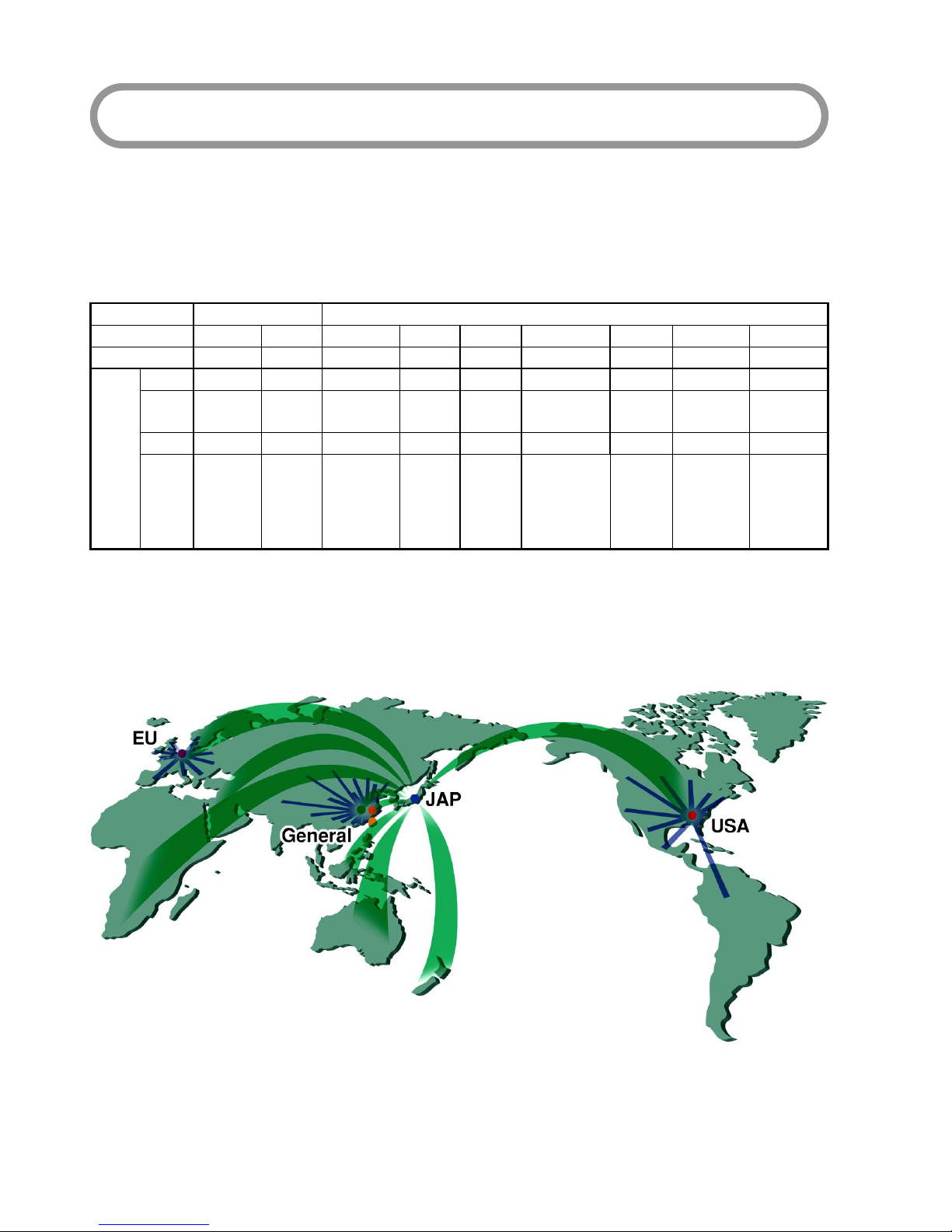
JAP, EU, General EU, General
Sales Region
(Reference) EU, General JAP EU, General USA USA JAP, General JAP, EU, General USA USA General EU, General JAP USA USA
Remarks
Cycle -2 ←←←2 ←←←←←←←←←
Number of Cylinders -1 ←←←1 ←←←←←←←←←
Valve Type -Piston valve ←←←←←←←←←←←←←
Cylinder Bore mm (in.) 32 (1.260) ←34 (1.339) ←38 (1.496) 40 (1.575) 43 (1.693) 44 (1.732) ←47.5 (1.870) ←←←50 (1.969)
Stroke mm (in.) 28 (1.102) ←←←26 (1.024) 33 (1.299) ←←←35 (1.378) ←←36.6 (1.441) ←
Displacement cm322.5 ←25.4 ←29.5 41.5 47.9 50.2 ←62 ←←64.9 71.9
Effective
Compression Ratio -7.7 ←8 7.4 7.4 8.1 8 7.8 7.3 7.7 ←←7.4 7.5
Fuel -Gasoline/oil mixed fuel ←←←←←←←←←←←←←
Engine lubrication -Fuel-oil mixture ←←←←←←←←←←←←←
Engine lubrication Oil -2-cycle oil ←←←←←←←←←←←←←
Mixing Ratio -
Zenoah FC 40:1
Normal FB 25:1
RedMax FD 50:1
←←←←←←←←←←←←←
Type -Diaphragm type
rotary valve ←←←←←←←←←←←←←
Carburetor
(Walbro) Model -WYJ-110A WYJ-374 WYA-26E WYA-65 USA, EU: WYA-73B
JAP: WYA-82 WYK-67A EU:WYA-51B
JAP:WYA-42B WYA-79 WYA-83 WYK-73A WYK-123A ←WYA-81 WYA-44B
Starting Method -Recoil starter
Recoil starter
(Coil dumper type: EZ) Recoil starter ←Recoil starter
(Coil dumper type: EZ) Recoil starter ←←←←←←←←
Type -
Analog controlled
TCI Flywheel
Magneto with
advance-angle
←
Analog controlled
CDI Flywheel
Magneto with
advance-angle
←←←←
Digital controlled
CDI Flywheel
Magneto with
advance-angle
Analog controlled
CDI Flywheel
Magneto with
advance-angle
←←←
Digital controlled
CDI Flywheel
Magneto with
advance-angle
←
Digital control Misfire
for excessive speed
Maximum speed:
85000 rpm
Ignition
System
Model -UK-08922-01 ←UK-08922-35 ←USA: UK-08958C-31
JAP, EU: UK-08958-31 ZMG-8 ZMG-10G UK-08963-54 ZMG-10G ZMG-8 ←←ZMG-14CGD ZMG-14GD
Ignition Timing °/ rpm 24/ 6000 ←35/ 7000 ←37/ 7500 28/ 7000 35/ 7000 33/ 7000 35/ 7000 28/ 7000 ←←34/ 7000 33/ 7000
Type -RCJ6Y ←CMR7A CMR7H ←RJ6C CMR7H ←←BPMR7A ←←CMR7H ←
Spark Plug Gap mm (in.) 0.6~0.7
(0.024~0.028) ←←←←←←←←←←←←←
Type -Primary coil
short-circuiting ←←←←←←←←←←←←←
LH -No setting Push type No setting Push type Toggle type No setting ←Push type ←←
Stopping
Method Switch RH -Push type ←←←Slide type ←←←←←←No setting Slide type ←
Cooling System -Forced air cooling ←←←←←←←←←←←←←
Air Cleaner
Element Type -Single layer dry
element ←←←←Single layer
half-wet element
Dual layer
half-wet element
Single layer
half-wet element ←←Primary: Dry puff
Secondary: Dry paper ←←←
Output Axle Rotation
Direction -Counterclockwise ←←←←←←←←←←←←←View from output
axle
Length mm (in.) 325 (12.8) ←327 (12.9) ←313 (12.3) 335 (13.2) 352 (13.9) 401 (15.8) ←336 (13.2) ←365 (14.4) 371 (14.6)
380 (15.0)/
USA: 390 (15.4)
Width mm (in.) 225 (8.86) 233 (9.17) 268 (10.55) 269 (10.59) 394 (15.5) ★489 (19.3)
/ 454 (17.9) 452 (17.8) ★483 (19.0)
/ 441 (17.4) ★483 (19.0) ★489 (19.3)
/ 454 (17.9) 449 (17.7) ★485 (19.1) ★487 (19.2)
/ 467 (18.4)
★540 (21.3)
/ 490 (19.3)
Throttle arm
Vertical state
Overall
Dimensions
Height mm (in.) 360 (14.2) ←←←420 (16.5) 495 (19.5) 476 (18.7) 495 (19.5) ←←←←←496 (19.5)
Dry Weight kg (lbs.) 3.7 (8.16) ←3.9 (8.6) 4 (8.82) 6.1 8.5 8.9 9.4 ←9.1 9.7 ←10.6 11.7/ USA:11. 5 Elbow included,
Blower pipe excluded
Fuel Tank Capacity L 0.75 ←0.65 ←1.08 1.8 1.9 2.1 ←2 2.1 ←←2.3
Idling Speed rpm 2300 ←2800 3000 3000 2000 2300 2200 ←2000 ←←←←
Operating Speed rpm 7500 ←7890 7600 6700 6350 6250 6000 5700 7700 7300 ←7050 6700
Blower Nozzle
Diameter mm (in.) 66 (2.60) ←←←←←66 (2.60)
Option: 55 (2.17) 66 (2.60) ←←←←←72 (2.835)
Average air volume at
aimed blowing point m3/ min 10 ←10.4 ←10.6 12 13.2 13.8 12.8 14 15 16.5 16.6 19.4
Maximum air speed at
aimed blowing point
(Calculated estimate)
m/ s 55.4 ←←←58.7 66.5 73.1 76.4 70.9 77.5 83.1 91.4 91.9 90.3
Maximum Output kW/ rpm
(PS)
0.86/ 8000
(1.17)
←
←
0.88/ 7500
(1.2)
0.86/ 7500
(1.17)
0.95/ 7500
(1.29)
1.80/ 8000
(2.45)
1.88/ 8000
(2.56)
1.62/ 7500
(2.2)
1.53/ 7500
(2.08)
2.87/ 7500
(3.9)
3.1/ 7000
(4.1)
3.1/ 7000
(4.1)
2.98/ 8000
(4.05)
3.29/ 8000
(4.48)
Fuel Consumption L/ h 0.8 ←0.59 0.51 0.59 1.7 1.05 1.1 0.98 1.9 ←←1.65 1.85 Under actual blower
state
Ambient noise at
15 m from the blower dB (A) 70 ←69 72 69 74 67 71 68 75 ←←77 77 ANSI B175.2-2000
Noise at operator
(Reference value) dB (A) 91 ←95 92 91 99 92 94 92 97 99 ←100 100
Sound Power Level dB (A) 106 ←106 ←100 106 104 104 102 110 107 ←110 112 ISO 11094

3
2. Specifications and Technical Data
2-2 Pipe Unit: mm (in.)
Part Name Grip Assembly Vacuum Kit Pipe End Straight Pipe+
++
+Duckbill Nozzle
Form
Standard D=φ60 (2.36) D=φ74 (2.91) D=φ80 (3.15) φ73 (2.87)×φ66 (2.60) φ73 (2.87)×φ57 (2.24) φ79 (3.11)×φ66 (2.60) φ79 (3.11)×φ72 (2.84) Forφ73 (2.87) Forφ79 (3.11)
RedMax Lodo 6811-51220 (Standard) 2756-51220 (Option) 848-L5C-65E1 (Standard) 848-L58-65E1 (Standard)
Part
Number Solid Color
3495-51400
(Option)
2750-51501
(Standard)
848-L58-6521
(Standard)
-
(Option)
848-L0L-65E0 (Standard) 848-L38-65E0 (Option) 848-L5K-65E1 (Standard) 848-L5Z-65E0 (Standard)
6811-51211+6811-51230
(Option)
848-L58-65D0+848-L58-65L0
(Option)
EB430/
EBE440 ●●
+(2750-51200 Swivel Joint)
HB2302/
HB2311EZ/
HBZ2601
-
-
-
●●●(Option) ●
EBZ3000
-
-
-
●●(Option) ●
EB4300/
EB6200/
EB7000
●●●(Option) ●
EBZ4800 ●●●(Standard) ●
EBZ5100Q ●●●(Option) ●
EBZ5100/
EB7001 ●●●(Option) ●
EBZ7100 ●●(Standard) ●(Option) ●
Model
EBZ8001 ●●(Option) ●(Standard) ●
Part Name Flexible Pipe Swivel Joint Straight Pipe Silencer Pipe End
Form
Diameter: D φ87 (3.43) φ87 (3.43) φ94 (3.70) φ99.5 (3.92) φ70 (2.76) φ70 (2.76) φ80 (3.15) φ61 (2.40) φ74 (2.91) φ80 (3.15) φ74 (2.91) φ61 (2.40) φ73 (2.84) φ73 (2.87) φ79 (3.11) φ79 (3.11)
Diameter: D1 φ70 (2.76) φ70 (2.76) φ70 (2.76) φ80.5 (3.17) φ60 (2.36) φ74 (2.91) φ79 (3.11) φ60 (2.36) φ73 (2.87) φ79 (3.11) φ73 (2.87) φ57 (2.24) φ66 (2.60) φ57 (2.24) φ66 (2.60) φ72 (2.84)
Standard
Length: L 420 (16.54) 372 (14.65) 345 (13.58) 345 (13.58) 370 (14.57) 340 (13.39) 365 (14.37) 370 (14.54) 320 (12.60) 365 (14.37) 346 (13.62) 355 (13.98) 340 (13.39) 340 (13.39) 340 (13.39) 340 (13.39)
RedMax Lodo
-
6811-51220 2756-51220 848-L5C-65E1 848-L58-65E1
Part
Number Solid Color 3495-51110 T4017-51110 T4030-51110 848-L65-65A0 3495-51202 2750-51201 848-L58-6511 3495-51321 6811-51211 848-L58-65D0 T4030-51110 3495-51300 848-L0L-65E0 848-L38-65E0 848-L5K-65E1 848-L5Z-65E0
EB430/
EBE440 ●●●
-
●
HB2302/
HB2311EZ/
HBZ2601
-
-
-
-
-
-
-
●
-
●
EBZ3000 ●●●
-
●
EB4300/
EB6200/
EB7000
●●●
-
●
EBZ4800 ●●
-
-
-
●●●
EBZ5100Q ●●
-
-
-
●●
EBZ5100/
EB7001 ●●●
-
●
EBZ7100 ●●●
-
●
Model
EBZ8001 ●●●
-
●
Diameter: D
φ66
(2.60)
φ57
(2.24)
φ66
(2.60)
φ72
(2.84)
23 (0.91)
138 (5.43)
D
D1
L D
D1
L D
D1
L D
D1
L D
D1
L
30 (1.18)
180 (7.19)

4
2. Specifications and Technical Data
2-3 Overall dimensions
Handheld Blower
Backpack Blower
Unit: mm (in.)
Blower Type A B C D
HB2302 325 (12.8) 225 (8.86) 360 (14.2) 610 (24.0)
HB2311EZ 325 (12.8) 233 (9.17) 360 (14.2) 610 (24.0)
HBZ2601 268 (10.55)
HBZ2601 (USA) 327 (12.9) 269 (10.59) 360 (14.2) 610 (24.0)
Unit: mm (in.)
Blower Type A B BB C D
EBZ3000/ 3000RH/ 3050/ 3050RH 313
(12.3) ―394
(15.5)
420
(16.5)
1222
(48.11)
EB4300 335
(13.2)
489
(19.3)
454
(17.9)
495
(19.5)
1222
(48.11)
EBZ4800 352
(13.9) ―452
(17.8)
476
(18.7)
1248
(49.13)
EBZ5100/ 5100RH/ 5150/ 5150RH 401
(15.8)
483
(19.0)
441
(17.4)
495
(19.5)
1195
(47.05)
EBZ5100Q/ 5150Q 401
(15.8)
483
(19.0) ―495
(19.5)
1221
(48.07)
EB6200 336
(13.2)
489
(19.3)
454
(17.9)
495
(19.5)
1222
(48.11)
EB7000 336
(13.2) ―449
(17.7)
495
(19.5)
1222
(48.11)
EB7001 365
(14.4)
485
(19.1) ―495
(19.5)
1195
(47.05)
EBZ7100/ 7100RH/ 7150/ 7150RH 371
(14.6)
487
(19.2)
467
(18.4)
495
(19.5)
1185
(46.65)
EBZ8001 380
(15.0)
EBZ8001/ 8001RH/ 8050/ 8050RH:
USA
390
(15.4)
540
(21.3)
490
(19.3)
496
(19.5)
1185
(46.65)
RH: Right hand throttle lever specification

5
3. Special Tools
3-1 Rotor Removal
Description
Part Name
Part Number
Model
Stopper
2670-96220
1664-96410
Stopper
3350-96220
Stopper
4810-96220
Puller Assy
2890-96100
Puller Assy
1490-96101
Puller Assy
2750-96100
Wrench (HEX)
3304-97611
Size: 3/4/5 mm
Wrench (TORX)
2850-96410
Size: T20/ T25/ T27
HB23 Series ●●●
HBZ26 Series ●●
EBZ30 Series ●●●
EB4300/ 6200
EB70 Series ●●●
EBZ4800
EB51/ 71/ 80 Series ●●●
Remove the rotor using the puller assy (special tool) while preventing piston movement by setting the stopper
(special tool).
Examples of special tool usage and maintenance procedures categorized by type and series are explained
below. Each drawing includes information on parts such as mount screws and disassembly cautions.
How to use (Procedure) Handheld Blower: HB23 Series, HBZ26 Series
1. Remove the plug, and detach the main complete
parts. Remove the carburetor, recoil starter and
fuel tank if necessary.
【
【【
【Disassembly Flowchart】
】】
】
Volute Cover Assy.
↓
Engine Cover
↓
Below the procedure
Volute Cover Assy.
Mounting Screw (5)
【
【【
【HB23 Series】
】】
】:
(+): P5×L20
【
【【
【HBZ26 Series】
】】
】:
TORX (T27): P5×L20
Mounting Screw (7)
(+): P5×L20
Mounting Screw (7)
TORX (T27): P5×L20
【
【【
【HB23 Series】
】】
】
Mounting Screw (1)
(+): M4×L14 (PW)
Mounting Screw (2)
TORX (T27): M5×L16
*Installing with the recoil starter.
Engine Cover
Engine Cover
Engine Short Block
Volute Case
【
【【
【HBZ26 Series】
】】
】
Construction

6
3. SPECIAL TOOLS
Handheld Blower: HB23 Series, HBZ26 Series
2. Set the stopper (special tool) into the plug hole.
3. Remove the mounting nut using the box wrench
then remove the fan.
4. Remove the extension using the wrench.
5. Remove the four mounting screws, separate the
volute case and the engine short block.
Stopper
【
【【
【HB23 Series】
】】
】【
【【
【HBZ26 Series】
】】
】
Stopper
Box Wrench
(12 mm)
Mounting Nut
(12 mm Hex)
Washer
Washer
Fan
Extension
Wrench (17 mm)
Mounting Screw
【
【【
【HB23 Series】
】】
】:
(+): M5×L14 (PW, SW)
【
【【
【HBZ26 Series】
】】
】:
TORX (T27): M5×L14
Engine Short Block
Volute Case

7
3. Special Tools
Handheld Blower: HB23 Series, HBZ26 Series
6. Remove the rotor using the puller assy.
Apply 8 mm puller bolts.
How to use (Procedure) Backpack Blower: EBZ30 Series
1. Remove the plug, and detach the main complete
parts. Remove the carburetor, recoil starter and
fuel tank if necessary.
Rotor
Puller Assy
Puller Bolt (8 mm) 17 mm
【
【【
【Disassembly Flowchart】
】】
】
Air Inlet Net
↓
Spring Damper
↓
Frame
↓
Volute Cover Assy
↓
Engine Cover
↓
Below the procedure
Volute Cover Assy.
Mounting Screw (8)
TORX (T27): M5×L25
Mounting Screw (3)
Mounting Bolt (1)
(+): M5×L16
Mounting Screw (3)
TORX (T27): M5×25
Engine Cover
Engine Short Block
Volute Case
Air Inlet Net
Plate
Clip (4)
Frame
Mounting Nut (2)
M6
Mounting Screw (2)
TORX (T27/ P): M5×L70
Mounting Nut (2)
M5
Lower Damper
Refer to
“4-2 Air Inlet Net Removal”
Refer to
“4-3 Upper Spring Damper Removal”
Refer to
“4-4 Volute Cover Lower Damper Removal”
Construction

8
3. SPECIAL TOOLS
Backpack Blower: EBZ30 Series
2. Set the stopper (special tool) into the plug hole.
3. Remove the four mounting screws, then remove
the fan.
4. Remove the four mounting screws, separate the
volute case and the engine short block.
Stopper
Fan
Mounting Bolt
TORX (T27): M6×L30
Mounting Bolt
TORX (T27):
M5×L20
Engine Short Block
Volute Case

9
3. Special Tools
Backpack Blower: EBZ30 Series
5. Remove the mounting nut using the box wrench.
6. Remove the rotor using the puller assy.
Apply 8 mm puller bolts.
How to use (Procedure) Backpack Blower: EB4300/ 6200, EB70 Series, EBZ4800, EBZ51/ 71/ 80 Series
1. Remove the plug, and detach the main complete
parts. Remove the carburetor, recoil starter and
fuel tank if necessary.
【
【【
【Disassembly Flowchart】
】】
】
Air Inlet Net
↓
Frame
↓
Engine Cover
↓
Below the procedure
Rotor
Puller Assy.
Puller Bolt (8 mm)
Box Wrench
(12 mm)
Mounting Nut
(12 mm Hex)
Volute Cover Assy.
Mounting Screw (1)
Engine Cover
Engine Short Block
Volute Case
Lower Damper
A
ir Inlet Net
Upper Dumper
Clip (4)
Frame
Mounting Nut (2)
M6
Mounting Screw (4)
Refer to
“4-2 Air Inlet Net Removal”
Refer to
“4-4 Volute Cover Lower Damper Removal”
Refer to
“4-20 Upper Damper Assembly”
Exceptions for
EB4300/ 6200
Construction

10
3. SPECIAL TOOLS
Backpack Blower: EB4300/ 6200, EB70 Series, EBZ4800, EBZ51/ 71/ 80 Series
2. Set the stopper (special tool) into the plug hole.
3. Remove the four mount screws, then remove the
fan. The fan is detached but stays inside the volute
cover assembly and the volute case.
4. Remove the six mounting screws then remove the
engine short block from the volute case.
5. Remove the mounting nut using the box wrench.
6. Remove the rotor using the puller assy.
Rotor
Puller Assy.
Box Wrench
(12 mm)
Mounting Nut
(12 mm Hex)
Stopper
Fan
Mounting
Bolt
Volute Cover Assy.
Volute
Case
Mounting Bolt
Engine Short Block
Volute Case

11
3. Special Tools
3-2 Module Assembly
Description
Part Name
Part Number
Model
Gauge
3350-96240
T=0.4 mm
Gauge
2750-96240
t=0.3 mm
Gauge
848-8W4-0050
t=0.4 mm
Wrench (HEX) 3304-97611
Size: 3/ 4/ 5 mm
Wrench (TORX) 2850-96410
Size: T20/ T25/ T27
HB23 Series
HBZ26 Series
EBZ30 Series
●●
EB4300/ 6200
EB70 Series
EBZ4800/ 5100Q
●●
EBZ5100
EBZ71/ 80 Series ●●
Adjust the air gap between the rotor's magnetic steel and the module using the gauge (special tool).
Module Resistance
Model Engine Type Primary Side
(Iron Core ⇒Primary Lead)
Secondary Side
(Iron Core ⇒High Tension Lead)
Air Gap
mm (in.)
HB2302/ 2311EZ G23L 0.8 kΩ4.23 kΩ0.3~0.4 (0.012~0.016)
HBZ2601 GZ25N +Side 8.45 kΩ-Side 2.70 kΩ2.92 kΩ0.3~0.4 (0.012~0.016)
EBZ3000 GZ30N +Side 30.3 kΩ-Side 37.2 kΩ2.04 kΩ0.3~0.4 (0.012~0.016)
EBZ3000RH/ 3050RH GZ30N (USA)+Side 31.6 kΩ-Side 37.4 kΩ2.05 kΩ0.3~0.4 (0.012~0.016)
EB4300 G4K 0.17 kΩ1.4 kΩ0.3~0.4 (0.012~0.016)
EBZ4800 GZ48N
EBZ5100Q/ 5150Q GZ51N
0.33 kΩ2.77 kΩ0.3~0.4 (0.012~0.016)
EBZ5100/ 5100RH
EBZ5150/ 5150RH GZ51N +Side 71.2 kΩ
-Side: cannot be measured 11.0 kΩ0.35~0.45 (0.014~0.018)
EB6200/ 7000/ 7001 G62L 0.17 kΩ1.4 kΩ0.3~0.4 (0.012~0.016)
EBZ7100/ 7100RH
EBZ7150/ 7150RH GZ65N Several MΩor higher 2.74 kΩ0.35~0.45 (0.014~0.018)
EBZ8001/ 8001RH
EBZ8050/ 8050RH GZ72N Several MΩor higher 2.72 kΩ0.35~0.45 (0.014~0.018)
The resistance values shown above are the
reference values for resistance tester
measurement. The resistance value is within
the normal range shows no internal leakage
or any other defect.
We supply the measurement equipment (gap
tester) that can measure spark energy while
the engine is running.
3699-90247
Three-point gap tester
* Connect Negative Side (black) to Iron Core.
REFERENCE

12
3. SPECIAL TOOLS
Examples of the gauge (special tool) usages are shown according to the type of the gauge.
Gauge: 3350-96240 (T=0.4 mm) HB23 Series, HBZ26 Series, EBZ30 Series
1. Remove the obstructive parts in order to see the
rotor and the module.
(Refer to “3-1 Rotor Removal”.)
2. Insert a gauge (special tool) between the rotor
magnet metal and module. Tighten the mounting
bolts while pushing the module against the rotor.
【
【【
【HB23 Series】
】】
】
Module
Rotor Wrench
Gauge
Mounting Bolt
【
【【
【HBZ26 Series】
】】
】
Module
Rotor Wrench
Gauge
Mounting Bolt
【
【【
【EBZ30 Series】
】】
】
Module
Rotor
Wrench
Gauge
Mounting Bolt
This manual suits for next models
24
Table of contents
Other Zenoah Blower manuals

Zenoah
Zenoah EBZ3000RH User manual

Zenoah
Zenoah EBZ7500 User manual

Zenoah
Zenoah STRATO-CHARGED EBZ4800 User manual

Zenoah
Zenoah EB4401 User manual

Zenoah
Zenoah EBZ5000 Owner's manual

Zenoah
Zenoah EBZ8550 User manual

Zenoah
Zenoah HB2302 User manual

Zenoah
Zenoah EBZ5100Q Manual

Zenoah
Zenoah EBZ100-CA User manual

Zenoah
Zenoah EBZ3000RH User manual

Zenoah
Zenoah EBZ5100 User manual

Zenoah
Zenoah EBZ3000RH Manual

Zenoah
Zenoah EBZ7100RH User manual

Zenoah
Zenoah HBZ2601 User manual

Zenoah
Zenoah EBZ7500 User manual

Zenoah
Zenoah EBZ8001-CA User manual

Zenoah
Zenoah Zenoah EB4300 User manual

Zenoah
Zenoah HB2302 User manual

Zenoah
Zenoah HBZ2600 User manual

Zenoah
Zenoah HB2302 Owner's manual