ZEP Dyna-Clean Troubleshooting guide

786-93885 1 of 14 6/6/22
ZEP DYNA PARTS WASHERS —SOLVENT
Model Dyna-Clean
Operations and Maintenance Instructions
Zep Inc.
3330 Cumberland Blvd. Atlanta, GA 30339
www.zepequipment.com
(Drum not included)

786-93885 2 of 14 6/6/22
SHIPPING INFO
Unpacking and Inspection
You should inspect your equipment for possible shipping damage. Note any damage on the BOL at
time of signing.
Thoroughly check the equipment for any damage that might have occurred in transit, such as broken or
loose wiring and components, loose hardware, and mounting screws, etc.
Contact the seller for further instructions.
INTRODUCTION
The Zep Dyna-Clean is a heavy-duty, industrial, and stable parts washers for cleaning with solvent-
based cleaners. An ideal choice for fast, efficient and economical cleaning of dirty or greasy parts. The
Zep Dyna-Clean meets or exceeds the OTC Freeboard Specifications.
Standard Features:
•Abrasive-resistant 170 GPH pump
•Reusable nylon filter sock removes large particles of dirt and grime from fluid to extend working
life
•Flexible Stay-Put plastic flush hose for directable hands-free flushing action
•Metal drain strainer prevents small parts from falling into cleaning solution tank
•16-gauge minimum welded steel tank leak tested for 24 hours after welding with powder-coat
finish for durability and long-life
•Fusible safety link closes lid in event of fire
•Lift-off sink for easy setup and maintenance, fast cleanup and fluid changes
•Freeboard compliant

786-93885 3 of 14 6/6/22
SAFETY WARNINGS/CAUTIONS
Read all of the SAFETY INSTRUCTIONS on the machine and those in the manual BEFORE
installing or using this equipment. Keep this manual handy for reference/training.
You will find various types of safety information on the following pages and on the labels attached to
Zeps equipment. The following Safety Statements explain their meaning.
This is the safety alert symbol. It is used to alert you to potential personal injury hazards. Obey
all safety messages that follow this symbol to avoid personal injury or death.
DANGER indicates a hazardous situation which, if not avoided, will result in death
or serious injury.
WARNING indicates a hazardous situation which, if not avoided, could result in
death or serious injury.
CAUTION, used with the safety alert symbol, indicates a hazardous situation which,
if not avoided, could result in minor or moderate injury.
CAUTION, without the safety alert symbol, is used to address practices not related
to personal injury.
Read and understand the user manual before operating this unit.
Do not operate above 100°F (38°C) maximum ambient temperature, near open flames, sparks, or
smoking materials. Keep cover closed when unattended.
To provide continued protection against risk of electrical shock, fire, and explosion, connect to
properly grounded supply or outlets only.
Risk of explosion. This equipment has internal arcing and sparking parts, which shall not be
exposed to flammable vapors. This equipmentshallnot be located in a recessed floor are orbelow
grade.
Only cleaning fluids with a flash point at or above 104°F (40°C) shall be used. Refer to user
manual for a list of solvents which have been evaluated for use.
For your protection and to maintain the performance of the cleaning process, do not contaminate
cleaning solution with fluids below 104°F (40°C) flash point. Do not dump gasoline, alcohol, used
oil, paint, lubricants, flammable liquids, chlorinated solvents, or other chemicals into this parts
cleaner. Even small amounts will create a hazardous condition.
Ensure fusible link and closing device are in proper working order. Fusible link melts at
165°F(74°C) causing lid to close. Whenopenthe lid must leanforward soit will close automatically
when link melts. Do NOT tamper with or remove the fusible safety link. If the safety link breaks or
is lost, do NOT use the unit. Replace the safety link immediately.
Hazardous voltage present. Disconnect power before repairing or cleaning. Unit must be properly
grounded to preventelectricshock, fire, and explosion hazard. Connect only tothree prong outlets.
Should cord become cracked, frayed, or damaged in any way, it should be repaired immediately
by a qualified electrician. Never use an extension cord. Since operator safety at all times is a
priority, we strongly recommend that, whether or not required by local code, this equipment be
connected only into a power supply equipped with a “Ground Fault Interrupter” (GFI). All electrical
connections should conform to national/local codes and be made by qualified personnel.
Do not leave objects in the tank or lethose attachments exit the tank whichprevent lid from closing
completely in the event of fire.

786-93885 4 of 14 6/6/22
Do not operate below minimum liquid level marking. Low liquid level may result in motor failure,
creating a potential fire hazard.Fill tank to recommended operating capacityrange before plugging
in power cord. Do not operate with drum empty.
Operator shall wear appropriate PPE (personal protective equipment). Refer to cleaning fluid SDS
(safety data sheet) for details. If any cleaning solutions are splashed on clothing, remove wet
clothing promptly and thoroughly wash body areas that have been in contact with the solution. Do
NOT permit saturated clothing to remain in contact with skin. Cleaning solutions may irritate skin
and eyes. If splashed in eyes, flush thoroughly with water. Consult Safety Data Sheet (SDS) and
a physician. Always wear appropriate safety items such as gloves, apron, safety glasses or
goggles.
Floor may be slippery when wet, do not splash fluids out of tank.
Use with solvent cleaningfluids only. The useof aqueous based (water) cleaningfluids will damage
the finish and cause rusting.
Install unit on level surface. Do not overload tank floor, shelf, or trays. Load items evenly, do not
allow items to overhang outside of the tank. Maximum load capacity is 100 lbs. Placing parts at
one end of tank can cause unit to become unbalanced and tip over.
Do NOT plug tank drain and fill. This also can cause unit to become unstable and possibly tip over.
Weight of liquid in drum affects stability. Keep filled to proper level.
Never work with equipment you feel may be unsafe. Contact your supervisor immediately if you
feel a piece of equipment is in an unsafe condition.

786-93885 5 of 14 6/6/22
SPECIFICATIONS AND DIMENSIONS
The Zep Dyna-Clean parts cleaner operates at 115V. To determine the electrical requirements of your
model, check the nameplate located on the side of the sink near the receptacle.
The Zep Dyna-Clean is designed to be used with combustible (flash point over 104°F) petroleum-based
cleaning fluids such as Zep Dyna 143, Dyna 170, Dyna Zone Defense, Dyna 680-T2, or Dyna 5202.
A
B
C
D
E
F
G
H min
H max
38.2"
27.2"
63.3"
30.6"
21.8"
9"
38.8"
10 gallons
20 gallons

786-93885 6 of 14 6/6/22
INSTALLATION AND OPERATION
The work area should be well ventilated.
Provide adequate lighting in the work area to allow observation of the cleaning process and the floor
area around the machine. Be sure to allow adequate room to bring work to and from the machine.
Provide sufficient clearance around the machine for fluid changeovers and servicing.
Site Preparation
Before installing, careful consideration should be given to the place of operation. Place unit on a
smooth, level surface. To the extent possible avoid installing machine in areas subject to high forklift
traffic. Reasonable precautions shall be taken to avoid damaging or puncturing the drum and sink
walls.
Installation Procedure
•Place cleaning tank on top of Zep 30 gallon open-head drum (Not included with machine).
Mounting ring on sink bottom should insert easily into drum and fully seat onto four mounting
brackets. If the sink does not fit into drum check drum for damage or out of roundness. If the
sink cannot be made to seat fully into the drum do not use the machine.
•Plug pump power cord into the receptacle on the back of electric box.
•Slip nylon filter sock onto drain cover. Position drain cover with filter bag in tank drain opening.
•Fill with appropriate cleaning fluid.
•Insert 3-prong plug into a properly grounded compatible outlet.
•Position light (If present) on rear of cleaning tank. Lift lock ring and lower light onto bracket post.
Release lock ring and check that light is secure on tank. Plug light power cord into the
receptacle on the back of electric box.
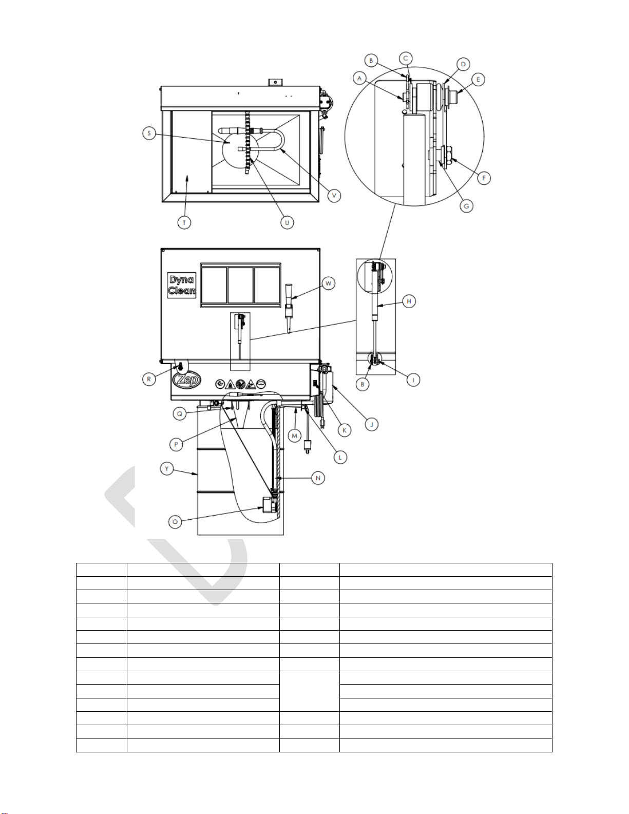
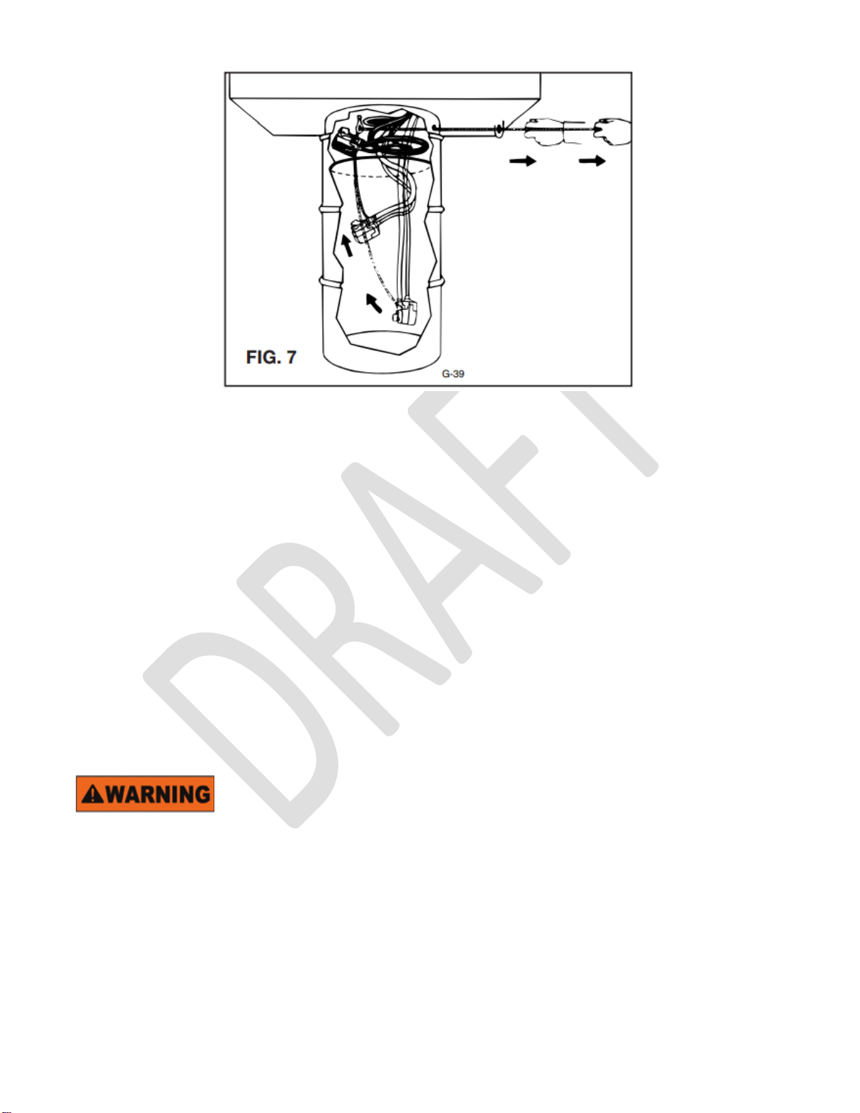
•Lower pump (Figure 2(O)) into drum by releasing the cable from bracket on right end of tank
and allow the pump to slowly pull cable into opening at left end of tank (Figure 3).
Unit is now ready for use.
Automatic Safety Cover
Open the lid on your Dyna-Clean and you will notice that it lifts simply and easily with one hand. There
is nothing to connect or disconnect to open or close the cover.
Your Dyna-Clean lid is equipped with a two-way gas spring (FIGURE 2(H)) that also incorporates a
fusible link (FIGURE 2 (D)). When open, the cover mechanism supports the cover at a slightly forward
angle. This angle is necessary to assure the cover’s fusible link will operate in the unlikely event of fire
in the tank. In the event of a fire, the fusible link will melt at 165°F permitting the lid to slam shut,
reducing oxygen supply to the fire.
Never leave the Dyna-Clean unattended with parts in the tank which would prevent the cover from
closing completely in the event of a fire. Ensure that brush hose is stored correctly inside the unit.
Always make sure that the cover remains in its correct, slightly tilted forward position when open. Do
NOT tamper with or remove the fusible safety link. If the safety link breaks or is lost, replace
immediately. Keep the cover closed when the unit is not being used.

786-93885 7 of 14 6/6/22
FIGURE 2
ITEM
DESCRIPTION
ITEM
DESCRIPTION
A
Gas Spring Stud
N
Tube, 1/2" ID
B
Cotter Pin
O
Pump
C
Flat Washer
P
Drain Filter Sock
D
Fusible Link
Q
Drain Hole Cover
E
Push Cap
R
Shut Off Valve
F
Bolt 1/4-20
S
Magnetic Sink Stopper
G
Sleeve
T
Trap Cover
H
Gas Spring
U
Flexible Plastic Hose
I
Clevis Pin
Flexible Plastic Hose –Valve
J
Canister Filter
Flexible Plastic Hose –Nozzle
K
Rocker Switch
V
Flow Thru Brush 14” Hose
L
Handle, T-bar
W
Stick Brush
M
Cable Assembly
Y
30 Gallon Drum (not included)

786-93885 8 of 14 6/6/22
FIGURE 3
THREE STAGE FILTRATION SYSTEM
The Zep Dyna Filtration system effectively removes unwanted greases and oils on a continuous basis
for more effective cleaning and longer solvent life.
NYLON FILTER SOCK
Removes large particles of dirt and grime to extend fluid life. It is recommended to remove and clean
nylon filter sock daily for optimum filtration of contaminants.
CANISTER FILTER
Replace the Zep canister filter every two months or when there is a reduction in flow rate from the
spout.
DYNA-TRAP FILTER BAG
Attach the Dyna-Trap by pushing the connector hose onto the hose-barb at the rear of the tank and turn
the “ON/OFF” switch to the ON position. Limited amounts of greases and oils are removed from
solvents as fluid percolates through the filter medium.
All models:
•Never work with equipment you feel may be unsafe. Contact your supervisor immediately if you
feel a piece of equipment is in an unsafe condition.
•Fill drum with Zep approved solvent cleaning fluid with flash point of 104°F (40°C) or higher.
Drum must contain enough fluid to submerge the pump but should not be more than 2/3 full.
•Insert plug into a properly grounded compatible outlet.
•This machine contains a flexible hose (FIGURE 2(U)) capable of splashing solvent and/or
ejecting it from the machine. The hose must be directed into the tank at all times and eye
protection worn while operating the equipment.
•Turn on rocker switch on right side of tank to start fluid recirculating.

786-93885 9 of 14 6/6/22
MAINTENANCE
Cleaning
Inspect pump, fusible link, and all electrical cords and plugs each time unit is cleaned. Do NOT use if
any wear or damage is noticed until impaired components are repaired or replaced.
Fill drum to recommended operating capacity range before plugging in power cord. (See
INSTALLATION AND OPERATION section.
To maximize fluid life and increase efficiency of the unit, the unit should be cleaned regularly. It is
recommended that the unit’s metal strainer and nylon filter sock located at the bottom center of the sink
be removed and cleaned daily for optimum filtration of contaminants and lengthened fluid life.
Changing Fluid
When it is determined that the cleaning fluid is no longer usable, remove the sink from the drum,
dispose of the contents in accordance with local regulations, wipe out drum and refill with fresh cleaning
fluid. To avoid buildup of sludge and grime, periodically wipe out sink.
Always dispose of used cleaning fluid properly. Refer to the cleaning chemical manufacturer’s package
label and solvent MSDS for instructions.
The pump supplied with this parts cleaner is retractable to protect it as well as to facilitate fluid
changeovers.
Raise pump by pulling cable straight out as far as it will go. Be sure to pull the cable straight out of the
hole to avoid scraping cable against sleeve opening (see Figure 3). Repeated scraping will cause cable
to fray and weaken.
Swing the cable over to opposite end of tank and insert into holding bracket. This will secure pump into
circular ring. Pump DOES NOT hang down, and therefore lift is much less.
Wiring instructions:
RECEPTACLE
GOLD SCREWS
SILVER
SCREWS
GREEN
SCREW
BLACK WIRE, 16AWG
WHITE WIRE, 16 AWG
GREEN/YELLOW WIRE, 14 AWG
ROCKER SWITCH
HOT
NEUT
GRD
GROUND STUD
18/3 SJO
CORD+PLUG

786-93885 10 of 14 6/6/22
TROUBLESHOOTING GUIDE
CONDITION
POSSIBLE CAUSE
CORRECTION
Pump
Pump does not run
Machine is unplugged
Plug machine into outlet
Pump is not plugged into
electrical box
Plug pump into electrical box
Circuit breaker is tripped
Check breaker and correct. If
problems persist, contact Graymills.
Pump motor is burned out
Replace pump
Faulty switch
Replace switch
Pump runs but does
not pump fluid
Pump filter screen is
clogged
Clear debris from around pump
Flexible plastic hose is
clogged
Clear debris from hose
Pump rubber discharge
hose clogged
Clear debris from hose or replace hose
Pump runs but does
not pump fluid
(external filter units)
Canister filter is clogged
Replace external filter
Pump runs but is
noisy (Some noise
is normal).
Cavitation due to low
liquid level
Raise liquid level to correct level
Optional Lamp
Light does not turn
on
Machine is unplugged
Plug machine into outlet
Light is not plugged into
electrical box
Plug lamp into electrical box
Circuit breaker is tripped
Check breaker and correct. If
problems persist, contact Graymills.
Bulb is burned out
Replace bulb
Faulty switch (on lamp)
Replace lamp

786-93885 11 of 14 6/6/22
REPLACEMENT PARTS
DESCRIPTION
PART
NUMBER
DRAWING REF.
Fuse Link
PWP0091
Figure 2 (D)
Gas Spring
PWP0087
Figure 2 (H)
Canister Filter –Fine
PWF0102
Figure 2 (J)
(* included with
machine)
Canister Filter –Medium *
PWF0202
Canister Filter –Coarse
PWF0302
Rocker Switch
PWP0090
Figure 2 (K)
Plastic “T” Handle
PWP0097
Figure 2 (L)
Cable Assembly
PWP0099
Figure 2 (M)
TUBE, ½” ID
PWP0098
Figure 2 (N)
Pump
PWP0086
Figure 2 (O)
Drain Filter Sock
PWP0096
Figure 2 (P)
Drain Hole Cover
PWP0093
Figure 2 (Q)
Magnetic Sink Stopper
PWP0088
Figure 2 (S)
Trap Cover
PWP0901
Figure 2 (T)
Flexible Plastic Hose
W38301
Figure 2 (U)
Flexible Plastic Hose - Nozzle
W38401
Flexible Plastic Hose - Valve
W38201
Flow Thru Brush
PWP0701
Figure 2 (V)
Stick Brush
PWP0092
Figure 2 (W)
30 Gallon Drum
903001
Figure 2 (Y)
Work Shelf (optional)
916501
‘not shown’
Hog Hair Filter (optional)
PWP0801
‘not shown’
Dyna-Trap Filter Bag (optional)
903402
‘not shown’
Work Light (optional)
PWP0401
‘not shown’

786-93885 12 of 14 6/6/22
LIMITED EQUIPMENT WARRANTY
Zep Inc warrants to the original purchaser that all equipment furnished by Zep will be free from defects
in material and workmanship under normal proper maintenance. Zep’s obligation under this Warranty is
limited to:
A. One year from date of purchase for parts and/or labor to repair or replace defective equipment.
AUTHORITY FOR ALL WARRANTY REPAIR SERVICES MUST BE COORDINATED BY THE ZEP
BRANCH FROM WHICH THE EQUIPMENT WAS PURCHASED.
Equipment or sub-assemblies are subject to return to the Zep Branch Office or Zep Branch Office
authorized service agency, or to: Zep Service Center
1400 Seaboard Industrial Blvd.
Atlanta, Georgia 30318
(404) 350-6287
Shipping charges to and from the Authorized Service Center or the Zep service center must be paid by
the Purchaser
Failures resulting from Purchaser’s misuse, sabotage, abuse, neglect, unauthorized alteration or repair,
lack of or proper maintenance, or by factors beyond Zep’s control, are the responsibility of the
Purchaser.
Warranty does not apply to expendable items, (lamps, belts, filters, etc.) or to components subject to
normal wear, (hoses, brushes, electrical cords, etc.)
Defective parts are to be returned to a Zep Branch Office, or to the Zep Service Center.
Parts that are replaced during the warranty period are only covered for the remainder of the machine
warranty period.
Zep reserves the right to make alteration in design and/or product improvements without obligation to
include these revisions in product previously manufactured. Correction of defects by repair or
replacement shall constitute fulfillment of all warranty obligations on behalf of Zep.
THIS WARRANTY IS IN LIEU OF ALL OTHER WARRANTIES, EXPRESSED OR IMPLIED, INCLUDING WARRANTIES OF
MECHANTABILITY OR FITNESS FOR A PARTICULAR PURPOSE, AND IS THE SOLE AND EXCLUSIVE REMEDY FOR
ANY CLAIM OR DAMAGE ARISING FROM ANY DEFECT IN EQUIPMENT FURNISHED BY ZEP. ZEP SHALL HAVE NO
LIABILITY FOR DIRECT, INDIRECT, OR CONSEQUENTAL DAMAGES, PERSONAL INJURY, LOSS OR EXPENSE
ARISING FROM THE USE OF ITS PRODUCTS. NO AGENT, DISTRIBUTION, OR OTHER PARTY IS AUTHORIZED TO
MAKE ANY WARRANTY ON BEHALF OF ZEP, OR TO ASSUME FOR ZEP ANY OTHER LIABILITY WITH RESPECT TO
ITS PRODUCT.

786-93885 13 of 14 6/6/22
DRUM MOUNTED PARTS WASHERS —SOLVENT
Model Dyna-Clean
Operations and Maintenance Instructions
*** PLACEHOLDER FOR ***
*** SPANISH TRANSLATED VERSION ***
Zep Inc.
3330 Cumberland Blvd. Atlanta, GA 30339
www.zepequipment.com

786-93885 14 of 14 6/6/22
DRUM MOUNTED PARTS WASHERS —SOLVENT
Model Dyna-Clean
Operations and Maintenance Instructions
*** PLACEHOLDER FOR ***
*** FRENCH TRANSLATED VERSION ***
Zep Inc.
3330 Cumberland Blvd. Atlanta, GA 30339
www.zepequipment.com
Table of contents
Other ZEP Washer manuals
Popular Washer manuals by other brands

Indesit
Indesit WITL 105 Instructions for use

Hoover
Hoover SE 160E Instructions for use

Smart+ Products
Smart+ Products SPP55AW instruction manual

Bosch
Bosch WAX28EH0GR User manual and installation instructions

Samsung
Samsung WF16J9000K Series user manual

Alliance Laundry Systems
Alliance Laundry Systems FLW1548C SVG user guide