Zeppelin Design Labs QUAVERATO User manual


2
QUAVERATO
HARMONIC TREMOLO PEDAL
Assembly Instructions
© 2018 ZEPPELIN DESIGN LABS. NO PART OF THIS DOCUMENT MAY BE REPRODUCED WITHOUT WRITTEN PERMISSION FROM THE AUTHOR. ZEPPELIN DESIGN LABS TAKES
NO RESPONSIBILITY FOR ANY DAMAGE OR HARM THAT MAY COME TO ANYONE OR ANYTHING THROUGH THEIR PRODUCTS. THE QUAVERATO SOFTWARE IS COVERED BY
THE CREATIVE COMMONS SHARE-ALIKE/ATTRIBUTION/NON-COMMERCIAL LICENSE, WHICH MEANS YOU ARE FREE TO ADD OR BUILD UPON THE CIRCUIT IDEA AND THE
SOFTWARE IN ANY WAY YOUR CREATIVITY ALLOWS, BUT ANY DERIVATIVES MUST BE SHARED USING THE SAME LICENSE.
110818
INTRODUCTION ...........................................................................3
WHAT’S IN THE BOX.....................................................................6
WHAT YOU WILL NEED ...............................................................10
POPULATING THE PRINTED CIRCUIT BOARD..................................10
PUTTING IT ALL TOGETHER ..........................................................36
CALIBRATION AND SETUP ...........................................................42
FINAL ASSEMBLY.........................................................................46

3
INTRODUCTION
The Quaverato is a versatile tap-time tremolo pedal, giving you a wide
range of control over the tremolo speed, depth, wave shape, and duty
cycle (or spacing). The Quaverato can also operate as a harmonic
tremolo, meaning it can apply tremolo independently to
the high and low frequencies. The HARMONIC MIX knob
allows you to blend the effect between these two frequency
ranges. Further, internal controls allow you to change the
cutoff frequencies, so you get to define what is high and what
is low. The Quaverato has an entirely analog signal path including
a true-bypass switching scheme, while still benefiting from the extended
functionality and versatility of digital control.
HOW TREMOLO WORKS
Tremolo is an effect in which the amplitude (or volume) of an audio signal is turned up and down (or
modulated) at a relatively slow rate. You can manually create tremolo by turning the volume knob of
your guitar or amp up and down at a constant rate, but tremolo is usually created electrically with a low
frequency oscillator (LFO) circuit. An LFO is a circuit that creates a relatively slow periodic waveform,
usually slower than 20 oscillations per second (20Hz). In a tremolo effect, the LFO essentially controls
a volume-changing component within the audio signal path.
SOME HISTORICAL CONTEXT
In the early 1940’s the DeArmond company of Toledo, Ohio started manufacturing the very first stand-
alone effect unit: an electro-mechanical tremolo. How this effect worked was very simple, but quite
clever. A variable-speed motor caused a grounded copper can to spin around. Inside this can was a
conductive liquid and an electrode connected to the audio input. As the can spun, the grounded liquid
would slosh around and come into contact with the electrode, causing the audio signal to be shunted
to ground. The audio signal would fade in and out at the rate of the sloshing liquid -- ingenius!
DeArmond originally designed their electro-mechanical tremolo box for use with
electric pianos, but by the 1950’s many guitar amplifier manufacturers
were implementing fully electrical tremolo effects in their amps.
The Fender Company was one of the most notable amp makers to
incorporate tremolo. Ironically enough, Fender mislabeled the effect
as “vibrato” on their amps. Vibrato is the effect which uses an LFO
to modulate the pitch (or frequency) of an audio signal, whereas
tremolo uses the LFO to modulate the volume (or amplitude). They
can sound very similar, but they are, in fact, two different effects. Some
people speculate that Fender labeled the amps “vibrato” to distinguish
them from the pitch-changing whammy bar on their Stratocaster guitar which
Fender was marketing as “tremolo” -- very confusing. It’s no wonder people still
get confused by the meaning of “tremolo” and “vibrato.”

4
Throughout the 1960’s Fender used several types of electrical tremolo circuits in their various amp
models, including
bias-modulating tremolo
,
optical tremolo
, and
harmonic tremolo
.
Bias tremolo is created by modulating the bias voltage on a preamp tube, phase inverter tube, or
power tube in an amplifier circuit. This has the effect of partially cutting off the current going through
the tube which reduces the tubes’ capacity to amplify the signal. Bias-modulated tremolo is associated
with a smooth, sine wave oscillation.
Optical tremolo is produced by using an optocoupler to modulate the signal in the preamp circuit of
an amp. Optocouplers contain a light dependent resistor (LDR) which is placed next to a light bulb (or
LED in modern optocouplers). The voltage to the light bulb is modulated, which in turn modulates the
resistance of the LDR, causing the signal to be variably attenuated. Optical tremolos create a pulsing
or throbbing sound, and tend to modulate the signal in a more lopsided manner, which tends to be
quite pleasing to the ear.
In a harmonic tremolo circuit the audio signal passes through a crossover circuit which splits the
low frequencies and high frequencies, sending them through their own circuit paths. The two frequency
ranges are modulated 180 degrees out of phase from each other: while one frequency range is on, the
other is off, and vice versa. Because the low frequencies and the high frequencies are separated from
each other, harmonic tremolo has a wonderfully subtle phasing sound that is quite mesmerizing. This
type of tremolo was found on many of Fender’s early brownface amps, but was soon replaced because
of the large number of expensive tubes and components that the circuit needed to operate. Due to the
frequency-shifting characteristics of harmonic tremolo, the effect actually comes close to true vibrato;
maybe Fender wasn’t too far off after all by calling one of their earliest tremolo circuits “vibrato”!

5
HOW THE QUAVERATO WORKS
The Quaverato is a very versatile tremolo pedal that produces all three types of tremolo sounds
mentioned above (bias, optical, and harmonic tremolo). When the guitar signal enters the pedal, it
is buffered with a low-gain amplifier stage and then immediately sent to the high pass and low pass
filters. The high pass filter (HPF) does exactly what it sounds like: it only lets high frequencies pass
through, and blocks the lower frequencies. The low pass filter (LPF) does just the opposite: it passes
low frequencies and blocks the high frequencies. See “Figure 2: Filters and Cutoff Frequency” on
page 6. The specific cutoff frequency for each of these filters is adjustable via an internal trimmer
potentiometer.
Next each signal is sent through a
unity gain amplifier and through
a digitally-controlled optocoupler.
Each optocoupler consists of a
light dependent resistor (LDR) and
a light emitting diode (LED). The
LDR is in series with the audio path.
When the LED is dark, the LDR’s
resistance is at maximum, which is
much too high for any audio signal
to get through. As the LED gets brighter, the LDR’s resistance lowers and allows signal to pass through.
At full brightness the LDR’s resistance is very low, allowing almost all of the signal to pass through.
The LED is digitally controlled by a microcontroller chip. This microcontroller produces an LFO which
causes the LED to turn on and off. The microcontroller has been programmed to give you a wide range
of control over how the LFO modulates the brightness of the LED.
Next the high and low frequencies are mixed back together. From there, the signal goes through a final
amplifier stage on its way to the volume control and finally the output jack.
For a complete discussion of the Quaverato’s features and controls, please see the Quaverato Owner’s
Manual, available from ww.zeppelindesignlabs.com.
Figure 1: Filter Crossover
Figure 2: Quaverato Block Diagram

6
WHAT’S IN THE BOX
”Table 1: Quaverato Harmonic Tremolo Pedal Bill of Materials” (BOM) is a complete parts list of
everything that should be present in your kit, followed by photos of each part. Print the BOM and
carefully go through the kit, identifying every part. Before opening
the silver static-protective bag, please read about the proper
handling of integrated circuits (ICs) in paragraph 10 on page
26. Note that some of the components are difficult to tell
apart. Compare them carefully with the photos. Besides verifying
that nothing is missing, this will acquaint you with the parts and
their names. If anything is missing, first double-check; we
double-checked before sealing the box at our lab! If it’s still
we goofed and shorted your kit, we will get replacement parts in the mail to you as soon as possible.
If you lose or damage anything, we will be glad to sell you replacements. You will need to order the
unusual or custom components from us, but for more common parts, like resistors, capacitors, or
screws, you may prefer to go to a local electronics or hardware store.
TIP: Empty the parts
of the kit into a bowl, NOT
onto the cluttered workbench, or
onto the living room carpet! This
will protect you from losing tiny
parts.
Figure 3: What’s In The Box

7
Table 1: Quaverato Harmonic Tremolo Pedal Bill of Materials
Part # Description Notes Qty
CB-06-30 Hookup Wire, 2" (5cm) x 5 wires 1
CB-90-13 Heat Shrink Tube, 3/16" x 1-1/2" (5x40mm) For Optocouplers 1
CD-10-12 Insulation Cardstock, 3/4" x 8" (2x20cm) 1
CH-10-30 Steel Chassis, Top & Bottom 2
CP-10-03 Electrolytic Cap, Radial 5x11mm 1uF C4 1
CP-10-08 Electrolytic Capacitor 220uF C14 1
CP-11-10 Electrolytic Cap, Radial 5x11mm 10uF C15 1
CP-20-07 Film Capacitor 22nF C2, C3 2
CP-20-16 Film Capacitor 1uF C1 1
CP-30-18 Ceramic Capacitor 1uF C7 - C13,C16 8
CP-30-19 Ceramic Capacitor 22pF C5, C6 2
CR-10-10 Crystal Oscillator 16MHz Y1 1
DI-20-01 Diode General Purpose 1N4007 1000V 1A D1, D2, D3 3
DI-30-32 LED, 3mm Green TAP LED 1
DI-30-36 LED, 3mm Red BYPASS LED, POWER LED 2
DI-30-52 LED, 5mm Green For Optocouplers 2
FA-60-32 Screw, Philips Pan Head #6 x 1/4” 4
HD-32-04 Knob 7
HD-40-01 ¼" TRS Audio Jack J1, J2 2
HD-40-10 DC Power Jack P1 1
HD-50-02 Grounding Solder Lug 1
HE-20-01 Header, Single Row, 10 Pins P2, MIDI IN 1
HE-25-28 Socket, 28 Pin U1 1
IC-22-20 J-FET Dual Op Amp, TL072 U2, U3 2
IC-26-39 Transistor, 2N3904 Q1, Q2 2
IC-30-60 Microcontroller, ATmega328-PU U1 1
IC-80-52 Voltage Regulator, 78L05 U5 1
PC-10-01 Quaverato PCB 1
PL-10-10 Quaverato Faceplate Sticker 1
PL-10-90 Serial Number Sticker 1
PT-10-26 Potentiometer, 16mm 100K VR2, VR3, VR4, VR5, VR6, VR7 6
PT-10-27 Potentiometer, 16mm 500K VR1 1
PT-30-10 Trim Pot, 10K VR8, VR9 2
PT-30-30 Trim Pot, 100K VR10 1
RL-30-01 Relay, HFD2-005-S-L2 RL1 1

8
CB-06-30 CB-90-13 CD-10-12 CH-10-30 C14
C4 C15 C2, C3 C1 C7 - C13,C16
C5, C6 Y1 D1, D2, D3 DI-30-32 DI-30-36
DI-30-52 FA-60-32 HD-32-04 J1, J2 P1
Part # Description Notes Qty
RS-80-32 Resistor, 220R R7, R8 2
RS-80-40 Resistor, 1K R4, R5, R6, R11, R12, R15 6
RS-80-50 Resistor, 14K R17, R21 2
RS-80-51 Resistor, 10K R2, R3, R13, R14, R16 5
RS-80-52 Resistor, 18K R18, R22 2
RS-80-54 Resistor, 36K R20, R24 2
RS-80-56 Resistor, 24K R19, R23 2
RS-80-61 Resistor, 100K R9, R10 2
RS-80-71 Resistor, 1M R1 1
SN-30-10 Light Dependent Resistor For Optocouplers 2
ST-60-39 LED Standoff, 9mm 3
SW-10-11 Footswitch, Momentary S1, S2 2
SW-20-15 Toggle Switch, SPDT S3, S4 2
SW-45-40 DIP Switch, 4 Position, SPST S5, S6 2

9
HD-50-02 P2, MIDI IN U1 U2, U3 Q1, Q2
IC-30-60 U5 PC-10-01 PL-10-10 PL-10-90
VR2 - VR7 VR1 VR8, VR9 VR10 RL1
R7, R8 R4-6, R11-12, R15 R17, R21 R2-3, R13-14, R16 R18, R22
R20, R24 R19, R23 R9, R10 R1 SN-30-10
ST-60-39 S1, S2 S3, S4 S5, S6

10
WHAT YOU WILL NEED
Here’s everything you will need to build the Quaverato kit.
TOOLS
1. Digital multimeter
2. #2 Philips screw driver
3. Small flat-head screwdriver
4. Needle nose pliers
5. Wire strippers
6. Small diagonal-cutting or flush-cutting pliers
7. X-ACTO®knife or hobby knife
8. 8mm, 10mm, 9/16” and 5/8” sockets and driver; in a pinch, pliers may work as well.
9. Soldering iron (not a soldering gun, or a “cold heat” iron), good quality, 15-50 watt. An iron with a
temperature control and a stand is best. Use a small or medium size tip, with conical or chisel shape.
10. Solder sucker or solder braid (optional, but very handy if you have to remove or repair any components!)
11. Damp sponge or dry solder-cleaning pad
12. Clamp or vise to hold the printed circuit board while soldering (optional, but handy)
SUPPLIES
1. Solder, 60/40 rosin core, small diameter, good quality. We prefer .032” [0.8mm] Kester brand, but most
brands will work fine.
2. Isopropyl alcohol and cleaning rag
3. Transparent tape or masking tape
4. Solder braid (AKA solder wick)
POPULATING THE PRINTED CIRCUIT BOARD
Your work space should be well-lit, well-ventilated, and disposable; that is, don’t work on the nice dining
room table! Work on a utility surface that you can burn, drill and scratch. A piece of ¼” tempered
masonite, or a chunk of MDF, makes an excellent surface if you don’t have a utility work bench.
CAUTION: Solder fumes are not healthy for you. The fumes consist of vaporized flux, which can
irritate your nose, lungs, and even your skin. You MUST work in a space where the air drifts away from
you as you work, so fumes do not rise straight into your face.
CAUTION: Solder residue usually contains lead, which is poisonous if you ingest it. Do not breathe
the fumes, do not eat the supplies, wash your hands after you handle solder, and sweep and wipe up
your work space after EVERY USE.

11
Your Quaverato tremolo pedal contains one printed circuit board (PCB). All of the components will be
installed on the “component side” of the board, which is the side with the part labels printed on it. The
other side of the board is called the “solder side,” which, as the name implies, is the side on which the
legs of most of the components are soldered. Proper technique for installing and soldering components
to a circuit board is demonstrated through several great resources on Instructables and Youtube under
the search “PCB soldering tutorial.” The general procedure consists of the following:
1. Install the part on the component side of the board, by threading the wire leads through the
appropriate holes in the board. For your convenience, the board has silk screen outlines
indicating where the components should be placed, along with text indicating the part number
and the component value.
2. Hold the component in place with your finger and turn the board over.
3. Gently bend the leads out at about 45 degrees to keep the component from falling out.
4. Install all of one type of component, bending each of the leads as they are installed.
5. Flip the board over solder-side-up, and solder all of the components in one pass.
6. Clip the leads off with small diagonal cutters, right at the solder joint.
Figure 4: Component Values and Locations

12
Let’s begin!
1. Resistors: The values of resistors are given by a series of colored stripes. There are several
tutorials online describing how to decode these stripes, but we will identify each resistor for you
by simply naming the stripe colors, and giving you the value and the part number. “Figure 4:
Component Values and Locations” on page 11 is a good reference. If you are color blind or
can’t see the stripes clearly, then you must use your digital multimeter to measure the resistance
of each resistor.
The white graphics on the component side of the board give reference to the part number and
value. Figure 4 shows the component values and locations and may be easier to read than the
graphics on the PCB, so please use it to cross check your work.
Resistors are not polarized, meaning they can be installed into their holes in either direction.
It doesn’t matter which lead goes into which hole. The hole spacing of the resistors on the
circuit board allows the leads to be (gently) bent 90 degrees at the body of the resistor (1). This
allows the resistors to slip into their holes very easily. Resistors R13, R14, and R17 - R24 are
exceptions. Note how those two components are bent (2).
1 2

13
a. Start with the 1K resistors (R4, R5, R6, R11, R12, R15), marked BROWN, BLACK, BLACK,
BROWN, BROWN. Compare to its picture in the BOM. Find their locations on the circuit
board; install and bend the leads out on the solder side as described above (3,4,5,6). Don’t
solder any of them until all 24 resistors are installed.
3 4
5 6
b. Install the 10K resistors (R2, R3, R13, R14, R16). These resistors are marked BROWN,
BLACK, BLACK, RED, BROWN (7). R13 and R14 stand upright on the PCB so bend one
lead nearly parallel with their bodies (8) and install them standing up (9,10). Bend the leads
out on the back so they won’t fall out.
7 8
910

14
c. Install the 220 ohm (220R) resistors (R7, R8), marked RED, RED, BLACK, BLACK, BROWN.
(11) Bend the leads on the back.
11
d. Next do the 100K resistors (R9, R10), marked BROWN, BLACK, BLACK, ORANGE,
BROWN. Bend the leads on the back.
e. Install the 1M resistor (R1), marked BROWN, YELLOW, BLACK, BLACK, BROWN. Bend the
leads on the back.
f. The rest of these resistors will be installed upright on the board (12). Install the 14K resistors
(R17, R21), marked BROWN, YELLOW, BLACK, RED, BROWN. Bend the leads.
g. Install the 18K (18K) resistors (R18, R22), marked BROWN, GREY, BLACK, RED, BROWN.
Bend the leads.
h. Install the 24K resistors (R19, R23), marked RED, YELLOW, BLACK, RED, BROWN. Bend the
leads on the back.
i. Lastly, install the 36K resistors (R20,R24), marked ORANGE, BLUE, BLACK, RED, BROWN.
Bend the leads. (13,14,15)
12 13
14 15

15
j. You should have a whole forest of bent leads coming out the solder side of the board. Now
you can turn the board solder-side-up and solder each lead to the board. Use a clamp or
vise if you have one; it makes soldering much easier (16,17).
16 17
k. Now clip each lead with your flush cutters at the solder joint (18,19).
18 19
l. Before installing any more components on the circuit board, double-check the resistance
values of each of the installed resistors (20). Set your digital multimeter to the “ohms” or
“resistance” setting, and measure across all of the resistors. Compare the measured value to
the listed value in Figure 4 on page 11. Make sure they are all correct (within 1%) before
moving on!
20

16
2. Diodes (D1,D2, D3): Diodes are polarized, meaning it matters which lead goes in which hole. If
you get it wrong your pedal won’t work. You will notice one end of the diode body has a white
stripe around it (21). The lead coming from the striped end of the diode goes in the hole with the
square pad. The lead coming from the non-striped end of the diode goes in the round pad.
WHITE STRIPE = SQUARE PAD
NO STRIPE = ROUND PAD
Place the diodes in their locations on the board (22,23). Gently bend the leads like you did for
the resistors. Before you solder them, double check to make sure they are installed in the correct
orientation. Solder and clip the leads (24).
21 22
23 24

17
3. Capacitors: There are three types of capacitors in the kit: ceramic (25), film (26) and electrolytic
(27). We will place them in the PCB one type at a time, and then solder them in groups.
25 26
27
a. Ceramic Caps: These caps look like little yellow blobs with two protruding leads. The
Quaverato uses two values of ceramic caps: 100nF and 22pF. The only noticeable
difference between these capacitors is the tiny label printed on their yellow bodies. The
100nF caps are labeled “104” and 22pF caps are labeled “22”. Please make sure that you
use the correct value in the correct location. Ceramic capacitors are not polarized. It doesn’t
matter which lead goes into which hole.
i. There are two 22pF ceramic capacitors (C5, C6), marked “22”. Install the 22pF
capacitors at C5 and C6 on the PCB and bend the leads out on the back (28,29).
ii. There are eight 100nF (=0.1uF) ceramic capacitors (C7-C13, C16). Place all the 100nF
capacitors in their respective places on the PCB and bend the leads out on the back.
Make sure you don’t accidentally put one of these 100nF ceramic caps in C1, which is
reserved for a .1uF film capacitor.
28 29

18
b. Film Capacitors: There are 3 film capacitors in the Quaverato. The two green film caps are
22nF (.022uF) in value and labeled “2A 223 J” (30). The red cap is 100nF (.1uF) in value
and labeled “104J” (31). These caps are not polarized; the leads can go into either hole.
30 31
i. Place the green 22nF caps (C2, C3) in their locations (32) and bend out the leads.
ii. Place the red 100nF cap (C1) in its place (33) and bend out its leads.
32 33
34
c. Electrolytic Capacitors: There is one 1uF cap (C4), one 10uF cap (C15), and one
220uF cap (C14). You can read their values on their casings. Electrolytic capacitors ARE
POLARIZED: there is a right way and a wrong way to install them. If you get it wrong, your
pedal will not work and the capacitor might burst. The white stripe on the case indicates the
side of the cap with the shorter, negative lead (27). The longer lead is positive. The longer,
positive lead goes into the hole with square pad; the shorter, negative, white-stripe lead goes
into the hole with the round pad.

19
STRIPE = NEGATIVE = SHORTER LEAD = ROUND PAD
NO STRIPE = POSITIVE = LONGER LEAD = SQUARE PAD
Make sure you orient these caps properly! For reference, Figure 4 on page 11 has little
red plus signs (+) on the positive pads.
i. Install C4 in its place and bend the leads out (35).
ii. Install C15 in its place and bend the leads out (36)
35 36
iii. Install C14 in its place and bend the leads out (37)
37
iv. Flip the board over, solder (38a) and snip all the capacitors’ leads (38b).
38a 38b

20
4. Crystal Oscillator (Y1): Place the crystal in the Y1 position on the PCB (the crystal is not
polarized) (39). Bend the leads out on the bottom; solder and clip the leads.
39
5. Headers (ISP and MIDI IN): We will now install the headers on the board to allow the Quaverato
to connect to other pieces of hardware.
a. By installing a 2x3 header array, you create an ISP (in-system programming) port. This is
a little socket that enables you to plug a cable into your pedal and upload (or “flash”) new
software onto the control chip (aka the microcontroller). The microcontroller in this kit comes
pre-programmed with the software needed to make your Quaverato work, but you can mod
or tweak the software and re-program the chip, if you are into that sort of thing. See the
Quaverato Owner’s Manual for more information about this. If you don’t ever plan on re-
programming your Quaverato then you can leave this header uninstalled.
Carefully break the header into three pieces: two pieces with three pins each, and one piece
with four pins. (Your kit may have been packaged with some pre-cut header pieces.) You can
use your fingers to do this (40). Insert the two 3-pin pieces in the pads markeed “ISP” (41).
The short pins go through the board; the long pins point up. Make sure the bottoms of the
headers are flat against the circuit board.
40 41
Other manuals for QUAVERATO
1
Table of contents
Other Zeppelin Design Labs Music Pedal manuals

Zeppelin Design Labs
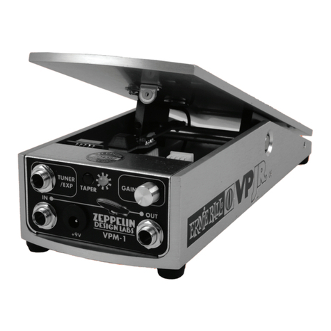
Zeppelin Design Labs VPM-1 User manual

Zeppelin Design Labs
Zeppelin Design Labs NOISETTE User manual

Zeppelin Design Labs
Zeppelin Design Labs ALTURA MKII Plus User manual

Zeppelin Design Labs
Zeppelin Design Labs QUAVERATO User manual

Zeppelin Design Labs
Zeppelin Design Labs QUAVERATO MIDI MOD User manual

Zeppelin Design Labs
Zeppelin Design Labs VPM-1 User manual